EP0165561A2 - Vorrichtung zur Behandlung von flachen Plättchen - Google Patents
Vorrichtung zur Behandlung von flachen Plättchen Download PDFInfo
- Publication number
- EP0165561A2 EP0165561A2 EP85107319A EP85107319A EP0165561A2 EP 0165561 A2 EP0165561 A2 EP 0165561A2 EP 85107319 A EP85107319 A EP 85107319A EP 85107319 A EP85107319 A EP 85107319A EP 0165561 A2 EP0165561 A2 EP 0165561A2
- Authority
- EP
- European Patent Office
- Prior art keywords
- support
- conveyer
- pins
- horizontal
- support elements
- Prior art date
- Legal status (The legal status is an assumption and is not a legal conclusion. Google has not performed a legal analysis and makes no representation as to the accuracy of the status listed.)
- Granted
Links
Images


Classifications
-
- H—ELECTRICITY
- H05—ELECTRIC TECHNIQUES NOT OTHERWISE PROVIDED FOR
- H05K—PRINTED CIRCUITS; CASINGS OR CONSTRUCTIONAL DETAILS OF ELECTRIC APPARATUS; MANUFACTURE OF ASSEMBLAGES OF ELECTRICAL COMPONENTS
- H05K13/00—Apparatus or processes specially adapted for manufacturing or adjusting assemblages of electric components
- H05K13/0061—Tools for holding the circuit boards during processing; handling transport of printed circuit boards
-
- H—ELECTRICITY
- H05—ELECTRIC TECHNIQUES NOT OTHERWISE PROVIDED FOR
- H05K—PRINTED CIRCUITS; CASINGS OR CONSTRUCTIONAL DETAILS OF ELECTRIC APPARATUS; MANUFACTURE OF ASSEMBLAGES OF ELECTRICAL COMPONENTS
- H05K3/00—Apparatus or processes for manufacturing printed circuits
- H05K3/0085—Apparatus for treatments of printed circuits with liquids not provided for in groups H05K3/02 - H05K3/46; conveyors and holding means therefor
Definitions
- This invention relates to treating devices for flat plates and more particularly to a device for holding and transporting a printed circuit board through a treating apparatus.
- a printed circuit board comprising a fiberglass core covered with a sheet of copper, over which is laminated a photosensitive layer, is imagewise exposed. Following exposure, the unexposed areas are removed and the underlying metal sheet uncovered. The uncovered metal areas can then be either etched or further metallized depending on the end result desired. Subsequently, the remaining photosensitive material which up to this point has been serving as a protective mask, is removed. Similar process steps may be employed when the printed circuit board is coated with a solder stop mask before the soldering process.
- the individual process steps are usually separated by a holding or waiting period during which the printed circuit board may be held for an intermediate treatment in a controlled environment, such as a drying oven, etc.
- such a holding and transporting device may form a part of a plate transport system, or of a continuous treatment or production process.
- the present invention is directed to a device for the treatment of planar members that are subjected to the same treatment during a number of cycles, comprising a vertical conveyer with support elements on which several members can be supported one above the other with a space between them on both sides: by an upper and a lower support plane situated one above the other laterally next to the vertical conveyer a horizontal conveyer situated in the region of the support planes that is capable of traveling towards the vertical conveyer and returning in every cycle, a first carrier that during the travel movement transports a member from a one support plane which is an entry support plane onto support elements of the vertical conveyer, and a second carrier that during the return movement transports a member from the support elements of the vertical conveyor onto another support plane which is an exit support plane.
- the instant invention relates to a holding and transporting device for planar members comprising:
- Rotation of the upright supports through this angle results in a flat plate supported by the plurality of pins on one level to be released and drop to a second level defined by the second plurality of pins brought into position within the enclosure as a result of the rotation of the upright supports.
- the angle of rotation is about 90°.
- a multitude of pins may be employed to define a multitude of parallel and distinct planes whereby a number of flat plates may be supported on alternate planes.
- the upright supports are rotated alternatively between a first and a second position, the members are dropped from one set of parallel planes defined by one set of pins to a second set of parallel planes defined by a second set of pins.
- Means may also be available to introduce a flat plate at the top horizontal plane from a supply of plates located adjacent the present device and means may be available to grasp and remove a flat plate from the bottom plane and to release it onto an outside transport device, for further treatment.
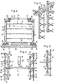
- a housing 2 that has an upper entry slot 3 and a lower exit slot 4, standing on a table 1.
- a vertical conveyor 6 in accordance with the present invention for holding and transporting a number of flat plates which in this instance are a number of printed circuit boards.
- the housing may comprise a dryer chamber 5 employing hot air injected therein by means of a blower 8.
- the details of the blower are not shown in this figure, such blower being conventional and well known in the art.
- An upper or entry support tray 9 is situated next to the entry slot 3.
- a lower or exit tray 10 is placed next to exit slot 4.
- a horizontal transport 13 is used to bring plates out of compartment 11 and into the dryer chamber 5.
- the transport 13 moves in the direction of arrow 14 on a set of rollers 15 on a guide 16 from a left hand position A shown in solid lines to a right hand position B shown in phantom lines.
- Transport 13 includes a frame 17 with an arm 18 extending downwardly. Mounted on this arm at the level of entry slot 3 is a first plate carrier 19 which serves to bring a plate into the conveyor 6. At the end of arm 18 near the level of exit slot 4 is placed a plate gripper 20 which serves to grip and remove a plate from conveyor 6.
- a second plate carrier 21 is mounted near the top of transport 13.
- Carrier 21 comprises a supporting plate on which are mounted several suction cups 22 which can be lowered onto the stack 12 by means of a driving cylinder 23 attached to the top of the transport 13.
- a number of upright supports 30 and 31 are mounted on the base of housing 2.
- the supports are mounted using mounting blocks 32 and 33 which are adjustably located on housing 2 by means of screws 34.
- the distance between uprights 30 and 31 may be varied depending on the size of the plate to be supported thereinbetween.
- Upright supports 30 and 31 are pivotally mounted around the axis extending along the long dimension of the support, on mounting blocks 32 and 34 using pins 70 and 70'. Upright supports 30 and 31 are fitted on the upper end with pivoting levers 35 and 36. Pivoting levers 35 are all pivotally connected to a connecting rod 37 and pivoting levers 36 are all pivotally connected to connecting rod 38. A set of roller bearings 42 and 43 are placed on connecting rods 37 and 38 respectively.
- cam rod 41 spans the space between connecting rods 37 and 38 and is placed so that bearings 42 and 43 ride on rod 47.
- a pneumatic drive 39 is mounted on the housing 2.
- a push rod 40 extending from the drive is connected to cam rod 41. The pneumatic drive can move rod 40 in the direction of arrow 44 on command.
- the plurality of upright supports 30 and 31 define an enclosure 72.
- the initial orientation of the upright supports 30 and 31 is such that the plurality of pins 25 extend into the enclosure while the plurality of pins 45 do not.
- a bottom plate 26 is located in the enclosure 72 on the lower portion of housing 2. Plate 26 extends above mounting blocks 32 and 34 and its top surface is on the level of exit slot 4.
- Fig. 6 there is shown the details of gripper 20.
- This gripper which is attached to the bottom end of transport arm 18 comprises a spring clip constructed by forming a single piece of a flat metal strap. It's back flange 46 is attached to arm 18. The front end forms two clamping arms 47 and 48 bent back diagonally to provide a pair of gripping jaws.
- Figure 8 shows a modified alternate embodiment for a gripper 120.
- One clamping arm 148 is used in this instance connected rigidly to the end of transport arm 18.
- a second clamping arm 147 made by bending a strap of metal which is joined to arm 18 using a hinge 159.
- An adjustable spring 160 permits to select the clamping force between the two arms.
- Figure 7 shows the details of a device employed near the exit slot 4 which permits the disengagement of a flat plate from the jaws of gripper 20.
- This device may be attached either onto the housing 2 or as shown in Fig. 1 form an integral part of the receiving device for receiving a printed circuit board released from the device subject of this invention.
- the gripper 20 is shown in its right hand position B. In that position, the gripper has moved past the release device stop 27.
- This device which may comprise a pin extending in the path of a flat plate held in the jaws of gripper 20 provides -a positive stop to the advance of the plate.
- a second pin 28 pneumatically driven through pneumatic cylinder 58. Pin 28 terminates in a pointed tip 50. Adjacent.
- a second pneumatic cylinder 53 is placed at a distance from tip 50 sufficient to permit passage of a flat plate.
- This second pneumatic cylinder terminates to a spring 5 4 connected to the cylinder through driving rod 55 .
- a number of flat plates to be treated may be stored on housing 2 under transport 13.
- the stack of plates may comprise a number of printed circuit boards which must be dried prior to further treatment.
- Suction cups 22 are lowered to grip the uppermost plate 7A of the stack 12 from position A and move it towards position 7B shown in phantom lines in Fig. 1.
- position B the suction is released and the plate falls into position 7C on support tray 9 next to entry slot 3.
- Transport 13 now returns to position A.
- the flat plate is pushed by first plate carrier 19 onto the top level of vertical conveyor 6 supported onto the first topmost set of pins 25 until it comes to rest against a stop 24 in position 7D.
- the plate is now wholly supported on pins 25.
- the pneumatic drive 39 is actuated pushing rod 40.
- connecting rods 37 and 38 are driven in the same direction as rod 40.
- Pivoting levers 35 and 36 follow the movement of rods 37 and 38 pivoting upright supports 30 and 31.
- the plurality of pins 25 is swung horizontally around an arc which moves them outside of the enclosure 72.
- the plurality of pins 45 are swung inwardly into the enclosure 72.
- the plate is no longer supported by pins 25 and falls through the action of gravity towards the bottom of housing 2.
- pins 45 located below pins 25 have now entered into the enclosure and interrupt the downward movement of the plate supporting it at a level below the original level.
- This action is repeated a number of times alternately bringing pins 45 and 25 in and out of the enclosure and slowly moving a plate from the upper portion of the housing towards the bottom of the housing.
- the transport 13 may be actuated to bring a fresh plate to the top level of the housing.
- a plate reaches the lowermost (7E) level of the housing it is gripped by gripper 20 which enters the lowermost portion of the housing through slot 4.
- the edge of the plate is inserted in the jaws of gripper 20.
- transport 13 moves away from the housing, the plate is carried with it outside of the housing. As the plate advances to position 7F the forward edge of the plate abutts against pin 27 whereby the movement of the plate is stopped.
- gripper 20 continues, thus releasing the plate from the jaws of the gripper.
- the pneumatic drive 53 is actuated lowering the spring 54 and driving the plate against pin 28.
- a predrilled hole 51 in the plate receives pin 28 and aligns the plat with respect to a fixed reference in the takeup device. The plate may now be removed for further treatment as desirably.
- the upright supports may be placed horizontally instead of upright.
- the upright supports do not carry a set of orthogonal pins, but a set of parallel pins which extend from the supports towards the inside of enclosure 72', defined by the supports.
- pivoting levers 35' and 36' connect the horizontal supports 30' and 31' to connecting rods 37' and 38'.
- four pneumatic drives 63 and 64 and 63A and 64A may be used to drive two sets of connecting rods 37' and 61 and 38' and 62.
- a bottom receiving plate 26' is again made available to receive a plate.
- a plate 7 is first entered in position C in this device.
- Pneumatic drives 64 and 64A are actuated pushing connecting rods 37' and 38' upwardly, thus lowering supporting pins 25' and dropping plate 7 onto supporting pins 45'.
- the plate is now in position D shown in phantom lines in the drawing.
- Pneumatic drives 64 and 64A are actuated again to return pins 25' to their original position.
- pneumatic drives 63 and 63A are actuated rotating pins 45' and releasing the plate to the next set of pins. Pins 45' are then returned to their original position and the cycle is repeated allowing the plate placed on top of the device to slowly advance towards plate 26' at the bottom.
- the supporting pins may be sufficiently long in order to eliminate plate sagging especially when thin plates are to be used.
- the device may be an enclosure in which a printing plate comprising a support base over which there is coated a photopolymerizable layer is treated with inert gas in order to flush oxygen from the photopolymer layer.
- This device is useful in any application where holding and individually treating flat plates is important in a process that is normally a continuous process and where limited space is available.
- gravity is disclosed as a convenient means for the plates, other means for moving the plates in an upward direction are also contemplated.
Landscapes
- Engineering & Computer Science (AREA)
- Manufacturing & Machinery (AREA)
- Microelectronics & Electronic Packaging (AREA)
- Specific Conveyance Elements (AREA)
- Photosensitive Polymer And Photoresist Processing (AREA)
- De-Stacking Of Articles (AREA)
- Reciprocating Conveyors (AREA)
- Intermediate Stations On Conveyors (AREA)
- Feeding Of Articles By Means Other Than Belts Or Rollers (AREA)
- Discharge By Other Means (AREA)
Applications Claiming Priority (2)
| Application Number | Priority Date | Filing Date | Title |
|---|---|---|---|
| DE19843422415 DE3422415A1 (de) | 1984-06-16 | 1984-06-16 | Vorrichtung zur behandlung von plattenfoermigen werkstuecken |
| DE3422415 | 1984-06-16 |
Publications (3)
| Publication Number | Publication Date |
|---|---|
| EP0165561A2 true EP0165561A2 (de) | 1985-12-27 |
| EP0165561A3 EP0165561A3 (en) | 1987-08-05 |
| EP0165561B1 EP0165561B1 (de) | 1991-05-29 |
Family
ID=6238519
Family Applications (1)
| Application Number | Title | Priority Date | Filing Date |
|---|---|---|---|
| EP19850107319 Expired EP0165561B1 (de) | 1984-06-16 | 1985-06-13 | Vorrichtung zur Behandlung von flachen Plättchen |
Country Status (4)
| Country | Link |
|---|---|
| EP (1) | EP0165561B1 (de) |
| JP (1) | JPS6160520A (de) |
| DE (1) | DE3422415A1 (de) |
| HK (1) | HK76191A (de) |
Cited By (3)
| Publication number | Priority date | Publication date | Assignee | Title |
|---|---|---|---|---|
| EP0703423A1 (de) * | 1994-06-23 | 1996-03-27 | General Signal Corporation | Schrittaufsteiger zum Senkrechttransportieren von Werkstücken im Ofen |
| WO2003041476A1 (de) * | 2001-11-05 | 2003-05-15 | Gebr. Schmid Gmbh & Co. | Verfahren und vorrichtung zum einbringen von flachen substraten in einen aufnahmebehälter |
| CN113895962A (zh) * | 2021-10-14 | 2022-01-07 | 上海达君玻璃有限公司 | 一种玻璃加工设备及工艺 |
Families Citing this family (2)
| Publication number | Priority date | Publication date | Assignee | Title |
|---|---|---|---|---|
| DE9317228U1 (de) * | 1993-11-10 | 1994-03-10 | Kuttler Handhabungstechnik Gmb | Vorrichtung zum Handhaben von Leiterplatten |
| DE19948131A1 (de) * | 1999-10-07 | 2001-04-12 | Schmid Gmbh & Co Geb | Einrichtung für das Beladen und Entladen bei der Behandlung von plattenförmigen Gegenständen |
Citations (4)
| Publication number | Priority date | Publication date | Assignee | Title |
|---|---|---|---|---|
| US3625377A (en) * | 1970-07-06 | 1971-12-07 | Western Electric Co | Stacked sheet feeder |
| DE2602622A1 (de) * | 1976-01-24 | 1977-07-28 | Kaspar Klaus | Vorrichtung zum transport von glasplatten |
| FR2495121A2 (fr) * | 1979-02-02 | 1982-06-04 | Limon Claude | Dispositif pour l'alimentation automatique en plaques, notamment de circuits imprimes, d'une machine travaillant au defile |
| EP0135117A2 (de) * | 1983-08-08 | 1985-03-27 | Tektronix, Inc. | Vorrichtung zum Transportieren von Gegenständen |
Family Cites Families (2)
| Publication number | Priority date | Publication date | Assignee | Title |
|---|---|---|---|---|
| DD86342A (de) * | ||||
| EP0055992B1 (de) * | 1978-03-28 | 1985-12-18 | E.I. Du Pont De Nemours And Company | Tonerzusammensetzung für magnetische Resistdruckverfahren |
-
1984
- 1984-06-16 DE DE19843422415 patent/DE3422415A1/de active Granted
-
1985
- 1985-06-13 EP EP19850107319 patent/EP0165561B1/de not_active Expired
- 1985-06-14 JP JP12840585A patent/JPS6160520A/ja active Pending
-
1991
- 1991-09-26 HK HK76191A patent/HK76191A/xx not_active IP Right Cessation
Patent Citations (4)
| Publication number | Priority date | Publication date | Assignee | Title |
|---|---|---|---|---|
| US3625377A (en) * | 1970-07-06 | 1971-12-07 | Western Electric Co | Stacked sheet feeder |
| DE2602622A1 (de) * | 1976-01-24 | 1977-07-28 | Kaspar Klaus | Vorrichtung zum transport von glasplatten |
| FR2495121A2 (fr) * | 1979-02-02 | 1982-06-04 | Limon Claude | Dispositif pour l'alimentation automatique en plaques, notamment de circuits imprimes, d'une machine travaillant au defile |
| EP0135117A2 (de) * | 1983-08-08 | 1985-03-27 | Tektronix, Inc. | Vorrichtung zum Transportieren von Gegenständen |
Cited By (6)
| Publication number | Priority date | Publication date | Assignee | Title |
|---|---|---|---|---|
| EP0703423A1 (de) * | 1994-06-23 | 1996-03-27 | General Signal Corporation | Schrittaufsteiger zum Senkrechttransportieren von Werkstücken im Ofen |
| WO2003041476A1 (de) * | 2001-11-05 | 2003-05-15 | Gebr. Schmid Gmbh & Co. | Verfahren und vorrichtung zum einbringen von flachen substraten in einen aufnahmebehälter |
| US7267522B2 (en) | 2001-11-05 | 2007-09-11 | Gebr. Schmid Gmbh & Co. | Method and device for the introduction of planar substrates into a receiving container |
| KR100928452B1 (ko) * | 2001-11-05 | 2009-11-25 | 게부르. 쉬미트 게엠베하 운트 코. | 평면기판을 수용용기에 삽입하는 방법 및 장치 |
| CN113895962A (zh) * | 2021-10-14 | 2022-01-07 | 上海达君玻璃有限公司 | 一种玻璃加工设备及工艺 |
| CN113895962B (zh) * | 2021-10-14 | 2023-08-11 | 浙江外界玻璃科技有限公司 | 一种玻璃加工设备及工艺 |
Also Published As
| Publication number | Publication date |
|---|---|
| JPS6160520A (ja) | 1986-03-28 |
| DE3422415C2 (de) | 1987-06-19 |
| EP0165561B1 (de) | 1991-05-29 |
| DE3422415A1 (de) | 1985-12-19 |
| EP0165561A3 (en) | 1987-08-05 |
| HK76191A (en) | 1991-10-04 |
Similar Documents
| Publication | Publication Date | Title |
|---|---|---|
| US4457658A (en) | Device for introducing a batch of sheets into a processing machine | |
| US4386464A (en) | Method and apparatus for mounting electronic components in position on circuit boards | |
| US5082268A (en) | Credit card dispensing and positioning apparatus | |
| US4178097A (en) | Automatic lithographic plate processor | |
| US4274529A (en) | Feed-retrieve device for sheet boards | |
| JPH0469506B2 (de) | ||
| US3997067A (en) | Apparatus for transporting successive printed circuit boards to and from a work station | |
| US4903818A (en) | Apparatus for inserting and/or removing printed circuit boards into and from slotted change pallets | |
| EP0165561B1 (de) | Vorrichtung zur Behandlung von flachen Plättchen | |
| US4565443A (en) | Printing apparatus | |
| JP3046976B2 (ja) | 製本機用排出装置 | |
| US4955506A (en) | Device for the individual withdrawal of sheet-type printed products, in particular newspapers | |
| US4141457A (en) | Transfer arm assembly for plate making system | |
| JPH06176992A (ja) | チップ部品の電極形成システム | |
| US4082455A (en) | Plate making system | |
| US3089693A (en) | Signature handling apparatus | |
| US4599122A (en) | Method of taping separation films for photoengraving and apparatus therefor | |
| JP2001289563A (ja) | 乾燥装置 | |
| GB1583436A (en) | Plate making system | |
| JP3365102B2 (ja) | 基板の投入方法及びその装置 | |
| JPH082000B2 (ja) | 電子部品装着装置 | |
| JPH03111371A (ja) | シート集積装置 | |
| JP3728419B2 (ja) | 露光すべき露光面の操作装置 | |
| JPS6216958A (ja) | 各種プレ−トの自動送給装置 | |
| JPH0619139A (ja) | 吸引台 |
Legal Events
| Date | Code | Title | Description |
|---|---|---|---|
| PUAI | Public reference made under article 153(3) epc to a published international application that has entered the european phase |
Free format text: ORIGINAL CODE: 0009012 |
|
| AK | Designated contracting states |
Designated state(s): BE CH FR GB IT LI NL |
|
| PUAL | Search report despatched |
Free format text: ORIGINAL CODE: 0009013 |
|
| AK | Designated contracting states |
Kind code of ref document: A3 Designated state(s): BE CH FR GB IT LI NL |
|
| 17P | Request for examination filed |
Effective date: 19871222 |
|
| 17Q | First examination report despatched |
Effective date: 19891002 |
|
| GRAA | (expected) grant |
Free format text: ORIGINAL CODE: 0009210 |
|
| AK | Designated contracting states |
Kind code of ref document: B1 Designated state(s): BE CH FR GB IT LI NL |
|
| ITF | It: translation for a ep patent filed |
Owner name: ING. C. GREGORJ S.P.A. |
|
| ET | Fr: translation filed | ||
| PLBE | No opposition filed within time limit |
Free format text: ORIGINAL CODE: 0009261 |
|
| STAA | Information on the status of an ep patent application or granted ep patent |
Free format text: STATUS: NO OPPOSITION FILED WITHIN TIME LIMIT |
|
| 26N | No opposition filed | ||
| PGFP | Annual fee paid to national office [announced via postgrant information from national office to epo] |
Ref country code: FR Payment date: 19930226 Year of fee payment: 9 |
|
| PGFP | Annual fee paid to national office [announced via postgrant information from national office to epo] |
Ref country code: CH Payment date: 19930302 Year of fee payment: 9 |
|
| PGFP | Annual fee paid to national office [announced via postgrant information from national office to epo] |
Ref country code: BE Payment date: 19930401 Year of fee payment: 9 |
|
| PGFP | Annual fee paid to national office [announced via postgrant information from national office to epo] |
Ref country code: NL Payment date: 19930630 Year of fee payment: 9 |
|
| PG25 | Lapsed in a contracting state [announced via postgrant information from national office to epo] |
Ref country code: LI Effective date: 19940630 Ref country code: CH Effective date: 19940630 Ref country code: BE Effective date: 19940630 |
|
| BERE | Be: lapsed |
Owner name: E.I. DU PONT DE NEMOURS AND CY Effective date: 19940630 |
|
| PG25 | Lapsed in a contracting state [announced via postgrant information from national office to epo] |
Ref country code: NL Effective date: 19950101 |
|
| NLV4 | Nl: lapsed or anulled due to non-payment of the annual fee | ||
| PG25 | Lapsed in a contracting state [announced via postgrant information from national office to epo] |
Ref country code: FR Effective date: 19950228 |
|
| REG | Reference to a national code |
Ref country code: CH Ref legal event code: PL |
|
| REG | Reference to a national code |
Ref country code: FR Ref legal event code: ST |
|
| PGFP | Annual fee paid to national office [announced via postgrant information from national office to epo] |
Ref country code: GB Payment date: 19970411 Year of fee payment: 13 |
|
| PG25 | Lapsed in a contracting state [announced via postgrant information from national office to epo] |
Ref country code: GB Free format text: LAPSE BECAUSE OF NON-PAYMENT OF DUE FEES Effective date: 19980613 |
|
| GBPC | Gb: european patent ceased through non-payment of renewal fee |
Effective date: 19980613 |