EP0165047A2 - Pseudo graphite electrode material obtained by pyrolysis - Google Patents
Pseudo graphite electrode material obtained by pyrolysis Download PDFInfo
- Publication number
- EP0165047A2 EP0165047A2 EP85304139A EP85304139A EP0165047A2 EP 0165047 A2 EP0165047 A2 EP 0165047A2 EP 85304139 A EP85304139 A EP 85304139A EP 85304139 A EP85304139 A EP 85304139A EP 0165047 A2 EP0165047 A2 EP 0165047A2
- Authority
- EP
- European Patent Office
- Prior art keywords
- electrode material
- poly
- battery
- carbonaceous material
- material according
- Prior art date
- Legal status (The legal status is an assumption and is not a legal conclusion. Google has not performed a legal analysis and makes no representation as to the accuracy of the status listed.)
- Granted
Links
Images


Classifications
-
- H—ELECTRICITY
- H01—ELECTRIC ELEMENTS
- H01M—PROCESSES OR MEANS, e.g. BATTERIES, FOR THE DIRECT CONVERSION OF CHEMICAL ENERGY INTO ELECTRICAL ENERGY
- H01M4/00—Electrodes
- H01M4/02—Electrodes composed of, or comprising, active material
- H01M4/36—Selection of substances as active materials, active masses, active liquids
- H01M4/58—Selection of substances as active materials, active masses, active liquids of inorganic compounds other than oxides or hydroxides, e.g. sulfides, selenides, tellurides, halogenides or LiCoFy; of polyanionic structures, e.g. phosphates, silicates or borates
- H01M4/583—Carbonaceous material, e.g. graphite-intercalation compounds or CFx
- H01M4/587—Carbonaceous material, e.g. graphite-intercalation compounds or CFx for inserting or intercalating light metals
-
- C—CHEMISTRY; METALLURGY
- C04—CEMENTS; CONCRETE; ARTIFICIAL STONE; CERAMICS; REFRACTORIES
- C04B—LIME, MAGNESIA; SLAG; CEMENTS; COMPOSITIONS THEREOF, e.g. MORTARS, CONCRETE OR LIKE BUILDING MATERIALS; ARTIFICIAL STONE; CERAMICS; REFRACTORIES; TREATMENT OF NATURAL STONE
- C04B35/00—Shaped ceramic products characterised by their composition; Ceramics compositions; Processing powders of inorganic compounds preparatory to the manufacturing of ceramic products
- C04B35/515—Shaped ceramic products characterised by their composition; Ceramics compositions; Processing powders of inorganic compounds preparatory to the manufacturing of ceramic products based on non-oxide ceramics
- C04B35/52—Shaped ceramic products characterised by their composition; Ceramics compositions; Processing powders of inorganic compounds preparatory to the manufacturing of ceramic products based on non-oxide ceramics based on carbon, e.g. graphite
- C04B35/524—Shaped ceramic products characterised by their composition; Ceramics compositions; Processing powders of inorganic compounds preparatory to the manufacturing of ceramic products based on non-oxide ceramics based on carbon, e.g. graphite obtained from polymer precursors, e.g. glass-like carbon material
-
- H—ELECTRICITY
- H01—ELECTRIC ELEMENTS
- H01M—PROCESSES OR MEANS, e.g. BATTERIES, FOR THE DIRECT CONVERSION OF CHEMICAL ENERGY INTO ELECTRICAL ENERGY
- H01M10/00—Secondary cells; Manufacture thereof
- H01M10/05—Accumulators with non-aqueous electrolyte
- H01M10/052—Li-accumulators
-
- H—ELECTRICITY
- H01—ELECTRIC ELEMENTS
- H01M—PROCESSES OR MEANS, e.g. BATTERIES, FOR THE DIRECT CONVERSION OF CHEMICAL ENERGY INTO ELECTRICAL ENERGY
- H01M4/00—Electrodes
- H01M4/02—Electrodes composed of, or comprising, active material
- H01M4/36—Selection of substances as active materials, active masses, active liquids
- H01M4/58—Selection of substances as active materials, active masses, active liquids of inorganic compounds other than oxides or hydroxides, e.g. sulfides, selenides, tellurides, halogenides or LiCoFy; of polyanionic structures, e.g. phosphates, silicates or borates
- H01M4/583—Carbonaceous material, e.g. graphite-intercalation compounds or CFx
-
- H—ELECTRICITY
- H01—ELECTRIC ELEMENTS
- H01M—PROCESSES OR MEANS, e.g. BATTERIES, FOR THE DIRECT CONVERSION OF CHEMICAL ENERGY INTO ELECTRICAL ENERGY
- H01M4/00—Electrodes
- H01M4/86—Inert electrodes with catalytic activity, e.g. for fuel cells
- H01M4/96—Carbon-based electrodes
-
- Y—GENERAL TAGGING OF NEW TECHNOLOGICAL DEVELOPMENTS; GENERAL TAGGING OF CROSS-SECTIONAL TECHNOLOGIES SPANNING OVER SEVERAL SECTIONS OF THE IPC; TECHNICAL SUBJECTS COVERED BY FORMER USPC CROSS-REFERENCE ART COLLECTIONS [XRACs] AND DIGESTS
- Y02—TECHNOLOGIES OR APPLICATIONS FOR MITIGATION OR ADAPTATION AGAINST CLIMATE CHANGE
- Y02E—REDUCTION OF GREENHOUSE GAS [GHG] EMISSIONS, RELATED TO ENERGY GENERATION, TRANSMISSION OR DISTRIBUTION
- Y02E60/00—Enabling technologies; Technologies with a potential or indirect contribution to GHG emissions mitigation
- Y02E60/10—Energy storage using batteries
-
- Y—GENERAL TAGGING OF NEW TECHNOLOGICAL DEVELOPMENTS; GENERAL TAGGING OF CROSS-SECTIONAL TECHNOLOGIES SPANNING OVER SEVERAL SECTIONS OF THE IPC; TECHNICAL SUBJECTS COVERED BY FORMER USPC CROSS-REFERENCE ART COLLECTIONS [XRACs] AND DIGESTS
- Y02—TECHNOLOGIES OR APPLICATIONS FOR MITIGATION OR ADAPTATION AGAINST CLIMATE CHANGE
- Y02E—REDUCTION OF GREENHOUSE GAS [GHG] EMISSIONS, RELATED TO ENERGY GENERATION, TRANSMISSION OR DISTRIBUTION
- Y02E60/00—Enabling technologies; Technologies with a potential or indirect contribution to GHG emissions mitigation
- Y02E60/30—Hydrogen technology
- Y02E60/50—Fuel cells
Definitions
- the present invention relates_to a novel electrode material, more particularly to an electrode material that is made of a carbonaceous material having a specific pseudographite structure and electron state and which is capable of making a lightweight and non-polluting electrochemical cell having high energy and maximum power densities.
- the present invention provides an electrode material suitable for use as battery electrodes.
- positive and negative electrodes made of the material of the present invention are submerged in a liquid electrolyte, an electromotive force can readily be generated by applying an external voltage so that the positive electrode is doped with negative ions, and the negative electrode with positive ions. Thereafter, the electrodes are connected to an external load and a current is caused to flow by removing the respective ions from the positive and negative electrodes. This cycle of. doping ions and removing them can be used as electrochemical charge and discharge reactions in the battery.
- a battery may also be constructed by using one electrode which is made of the material of thepresent invention and the other electrode made of a known material.
- activated carbon fibers as the material for the two electrodes is disclosed in Japanese Patent Application (OPI) Nos. 58-35881 and 59-149654. But the cells using such electrode materials generate an electromotive force as low as 1.2 to 2.9 volts. The cells have low energy densities while experiencing high self-discharge after charging.
- Japanese Patent Application (OPI) No. 58-93176 proposes a cell configuration that uses as the material for both electrodes a carbonaceous pyrolyzed polymer. But this cell produces low electromotive forces in the range of 1.2 to 1.4 volts and their short circuit current is as low as 30 ⁇ mA to 4 mA. Additionally, the cell has a fairly low energy density.
- an electroconductive polymer e.g., polyacetylene or polyparaphenylene
- an electroconductive polymer e.g., polyacetylene or polyparaphenylene
- the cell generated an electromotive force of 2.5 volts, an energy density of 150 W.h/hr and a maximum power density of 17 kW/kg.
- a negative electrode made of metallic lithium and a positive electrode made of the polymeric material were used, the respective cell parameters were 3.5 volts, 290 W.h/kg and 3.5 kW/kg.
- polyacetylene is unstable and is highly sensitive to oxidative deterioration, causing adverse effects on the cell performance such as cycle life. Furthermore, polyacetylene and polyparaphenylene are not easily dissolvable or meltable and cannot be shaped various forms of electrodes by ordinary methods.
- the present inventors made various studies to obtain an electrode material that is stable, generates a great electromotive force, has high maximum power and energy densities and which can be easily shaped into a variety of electrode forms. As a result, it has been found that this object can be achieved by using as an electrode material a carbonaceous material having a specified pseudographite structure and electron state.
- the present invention has been accomplished on the basis of the discovery.
- the carbonaceous material in accordance with the present invention is obtained by the pyrolysis of an organic compound capable of forming the graphite structure.
- This carbonaceous material has such a pseudographite structure that the spacing of (002) planes, d002 is at least 3.37 A and the crystallite size in the direction of c axis, Lc, is 0 not more than 220 A, as determined by X-ray wide-angle diffraction,
- the carbonaceous material has such an electron state that the line width ⁇ Hpp between peaks in the first differential of the absorption spectrum of electron spin resonance is at least 10 gauss.
- the electrode material in accordance with the present invention has a pseudo-graphite structure obtained by the pyrolysis of an organic compound capable of forming the graphite structure.
- the organic compound capable of forming the graphite structure as used in the present invention is such an organic compound that its carbon-carbon bonds will change to a benzene ring structure upon reactions such as decomposition and condensation and that a continuous one- and two-dimensional bonding of such benzene rings forms a plurality of stacked polycyclic aromatic planes.
- Polycyclic heterocyclic compounds are such that at least two monocyclic heterocyclic compounds consisting of a three- or more membered ring are condensed together or at least one such monocyclic heterocyclic compound is condensed with at least one monocyclic hydrocarbon compound consisting of a three- or more membered ring. Derivatives of such condensed products may also be used.
- condensed polycyclic hydrocarbon compounds are naphthalene, chrysene, pyrene, peryl- ene , na p h t h o an t h rene, terylene, pyranthrene, dibenzo(b,h)-chrysene, coronene, benzo(a)coronene, pentacene, ovalene and dibenzoperopyrene, as well as derivatives thereof.
- polycyclic heterocyclic compounds are isoquinoline, phenazine and phthalazine, as well as derivatives thereof.
- Preferred compounds are selected from the following group.
- Illustrative substituents are organic compounds such as carboxylic acids, carboxylic acid anhydrides and carboxylic acid imides that contain a hetero atom and easily undergo homolytic fission and wherein two groups are bonded together with (R is hydrogen or an alkyl group, an aryl group or an alkoxy group, having 1 to 10 carbon atoms) to form a ring structure.
- R is hydrogen or an alkyl group, an aryl group or an alkoxy group, having 1 to 10 carbon atoms
- the compounds which form a ring structure during pyrolysis such as those having two carboxylic acids on adjacent carbon atoms may also be used.
- Preferred compounds of group (A) are selected from the following group: benzene-l,2,4,5-tetracarboxylic acid, benzene-1,2,4,5-tetracarboxylic acid- dianhydride, and benzene-1,2,4,5-tetracarboxylic acid diimide; naphthalene; isoquinoline; phthalazine-l,4,5,8-tetracarboxylic acid, phthalazine-1,4,5,8-tetracarboxylic acid dianhydride, and phthalazine-1,4,5,8-tetracarboxylic acid diimide; perylene; perylene-3,4,9,10-tetracarboxylic acid, perylene-3,4,9,10-tetracarboxylic acid dianhydride, and perylene-3,4,9,10-tetracarboxylic acid diimide; terylene; terylene-3,4,11,12-tetracarboxylic acid,
- These compounds may have their carbon skeleton substituted by a halogen and such halogenated compounds may also be used.
- Linear novolak resins may be prepared by polycondensation of aldehyde compounds with mono-substituted phenols having a substituent on the ortho- or para-position.
- substituent X examples include alkyl groups such as methyl and nonyl, or halogens such as chlorine.
- aldehyde compounds are formaldehyde, paraformaldehyde, trioxane, acetaldehyde, furfural and acrolein.
- Formaldehyde, paraformaldehyde and trioxane are particularly preferred.
- the mono-substituted phenols and aldehyde compounds are polycondensed in the presence of an acidic catalyst selected from among mineral acids such as hydrochloric acid, nitric acid, sulfuric acid, phosphoric acid and perchloric acid, as well as from among organic acids such as p-toluenesulfonic acid and oxalic acid.
- an acidic catalyst selected from among mineral acids such as hydrochloric acid, nitric acid, sulfuric acid, phosphoric acid and perchloric acid, as well as from among organic acids such as p-toluenesulfonic acid and oxalic acid.
- a high-molecular weight ortho- and para-cresol copolymerized novolak resin and a process for producing the same are described in Unexamined Published -Patent Application No. 56-92908.
- a polar organic solvent i.e., alkyl alcohol or alkylcarboxylic acid
- the linear high-molecular weight novolak resins prepared by the methods described above generally have number average molecular weights of 1,000 or more as determined by VPO (vapor pressure osmometry), preferably, 1,200 or more, more preferably 1,500 or more, and most preferably 2,000 or more.
- VPO vapor pressure osmometry
- linear high-molecular weight novolak resin means those novolak resins which are soluble in - one of dimethylactamide, tetrahydrofuran and dioxane and which are substantially free from a gel component. Therefore, even novolak resins that have a small content of branched or network structure may be employed so long as they satisfy the requirement for solubility in the solvents listed above.
- the linear high-molecular weight novolak resin used in the present invention preferably contains a curing agent which helps its curing to varying degrees before it is pyrolyzed to form a polymeric conjugate.
- Suitable agents that may be used for the purpose of curing the linear high-molecular weight novolak resins include aldehyde compounds such as formaldehyde, paraformaldehyde, acetaldehyde and furfural, and other known cross-linking agents such as hexamethylene tetramine and trimethylol phosphine oxide.
- the linear high-molecular weight novolak resins may be cured by reaction with a resol - obtained by reacting phenol with an aldehyde compound in the presence of an alkali catalyst.
- Other usable curing agents are compounds having an epoxy group, such as epoxy resins.
- the amount of curing agent used varies with its type. If aldehyde compounds or epoxy compounds are used as the curing agent, their amounts are selected from the range up to 2.5 moles of the aldehyde compound or epoxy group per mole of the phenolic OH group in the linear high-molecular weight novolak resin. If hexamethylenetetramine or resol is used as the curing agent, their amounts are selected from the range up to 60 wt% of the linear high-molecular weight novolak resin.'
- Curing accelerators such as benzyldimethylamine, imidazoles, tris-dimethylaminomethyl phenol and BF 3 -piperidine salts, as well as a variety of fillers may optionally be used together with the curing agents.
- poly(haloacrylnitrile) examples are poly( ⁇ -haloacrylnitrile) and poly( ⁇ -haloacrylnitrile), which are respectively prepared by polymerizing a-haloacrylnitrile and ⁇ -haloacrylnitrile.
- Homopolymers are useful but copolymers containing small proportions of comonomers may be used.
- Suitable comonomers include those which contain a nitrile group such as acrylonitrile, and vinyl halide compounds such as vinyl fluoride.
- the a-haloacrylonitrile and ⁇ -haloacrylonitrile are monomers that are respectively represented by the following formulae (3) and (4):
- the poly( ⁇ -haloacrylonitrile) and poly( ⁇ -haloacrylonitrile) are usually obtained by radical polymerization of a-haloacrylonitrile and ⁇ -haloacrylonitrile, respectively.
- a copolymer of a-haloacrylonitrile and ⁇ -haloacrylonitrile may also be used in the present invention.
- the poly(halodicyanoethylene) is obtained by polymerizing a halocyanoethylene and includes a homopolymer of halodicyanoethylene, as well as a copolymer of halodicyanoethylene and a small amount of a comonomer.
- the halodicyanoethylene is a monomer represented by formula (5):
- the poly(cyanoacetylene) and poly(dicyanoacetylene) are polymers of cyanoacetylene and dicyanoacetylene which are respectively represented by formulae (6) and (7). Homopolymers are preferred but copolymers with small fractions of comonomers may be used.
- the electrode material is obtained by the pyrolysis of one or more polymers selected from among the above-mentioned poly( ⁇ -haloacrylonitrile), poly( ⁇ -haloacryloniarile), poly-(halodicyanoethylene), poly(cyanoacetylene) and poly(dicyanoacetylene).
- the poly( ⁇ -haloacrylonitrile), poly( ⁇ -haloacrylonitrile) and poly(halodicyanoethylene) may be pyrolyzed after they are subjected to the reaction of removal of hydrogen halide by treatment with a tertiary amine compound such as pyridine, DBU (1,8-diazabi- cyclo[4,3,0]undecene-7) or triethylamine, a phase transfer catalyst such as benzene-trimethyl ammonium hydroxide; sodium amide (used in liquid ammonia), alkali hydroxide (used at high temperatures and pressure), potassium butoxide, butyl lithium, the combination of an aqueous alkali solution and an amine compound, and a crown ether.
- a tertiary amine compound such as pyridine, DBU (1,8-diazabi- cyclo[4,3,0]undecene-7) or triethylamine
- a phase transfer catalyst such as
- Poly(phenylene) and poly(substituted phenylene) may be synthesized by several known methods. See, for example, "A Course in the Theory of Polymerization Reactions", 12, New Polymerization Reactions, ed. by T. Saegusa, p. 31, ff.
- these polymers are obtained by subjecting benzene or a substituted benzene to oxidative cationic polymerization in the presence of a Lewis acid-oxidant system such as AlCl 3 -CuCl 2 ⁇
- a preferred method for the synthesis of a high-molecular weight polyparaphenylene is disclosed by Marvel et al. in J. American Chemical Society, 81, 448 ff. (1959). This method consists of polymerizing 1,3-cyclohexadiene in the presence of a Ziegler catalyst such as Ti(OC 4 H 9 ) 4 -Al(i-G 4 H 9 ) 3 or a cationic catalyst such as BF 3 , followed by treatment with a dehydrogenating agent such as chloranil to make the desired poly(paraphenylene).
- a Ziegler catalyst such as Ti(OC 4 H 9 ) 4 -Al(i-G 4 H 9 ) 3 or a cationic catalyst such as BF 3
- a dehydrogenating agent such as chloranil
- the poly(phenylene) and poly(substituted phenylene) used in the present invention have an average degree of polymerization (n) of at least 5, preferably at least 7, more preferably at least 10.
- poly(phenylene) having excessively high molecular weights are neither soluble or meltable and defy exact measurement of its molecular weight.
- the poly(phenylene) and poly(substituted phenylene) that are insoluble in solvents and which hence defy exact measurement of their molecular weights will be regarded as having degrees of polymerization of 7 or more.
- Preferred poly(phenylene) is poly(paraphenylene) since a product with an adequately high molecular weight can be obtained fairly easily and at low cost.
- the organic compounds capable of forming the graphite structure are pyrolyzed either in vacuum or under an inert gas (e.g., nitrogen or argon) stream or an oxidizing gas (e.g., air) stream or a mixture of such streams.
- an inert gas e.g., nitrogen or argon
- an oxidizing gas e.g., air
- the organic compounds are pyrolyzed in vacuum or under an inert gas stream.
- carbon radicals (B) are formed predominantly by homolytic cleavage.
- a chain of carbon radicals is cyclized to provide a higher molecular weight and the process of graphitization occurs that is characterized by the development of polycyclic aromatic planes.
- benzene rings are bound together one-dimensionally to form a one-dimensional graphite structure (C).
- the benzene rings start to bind with one another two-dimensionally, and gradually expanding polycyclic aromatic planes begin to stack in layers to form a two-dimensional graphite structure (D).
- the same phenomenon will occur in the pyrolysis of other organic compounds capable of forming the graphite structure; the one-dimensional graphite structure (C) forms as a result of thermal decomposition or condensation, and subsequently a structure similar to the two-dimensional graphite structure (D) forms.
- the organic compounds capable of forming the graphite structure may be carbonized not only by application of thermal energy but also by irradiation by light energy greater than the dissociation energy, as well as by irradiation by accelerated charged particles such as Br + or Ar+ or by plasma irradiation.
- the graphitization reaction of the organic compounds may proceed in any one of the three states, molten, solid and gaseous.
- the carbonaceous material thus obtained in accordance with the present invention is very stable and will hot deteriorate upon standing in air at room temperature.
- the pseudo-graphite structure in accordance with the present invention can be determined both qualitatively and quantitatively by X-ray wide angle diffraction.
- no diffraction peak corresponding to the (002) plane does not appear.
- the one-dimensional graphite obtained by further pyrolysis has a very broad diffraction peak corresponding to the (002) plane and its intensity is low.
- the diffraction peak corresponding to the (002) plane gradually becomes sharp and its intensity increases.
- the pseudo-graphite structure which characterizes the carbonaceous material of the present invention is such that the spacing of (002) 0 planes, d002, is at least 3.37 A and the crystallite size in the direction of c axis, Lc, is not more than 220 A.
- d002 is at least 3.40 A and not more than 3.75 A
- Lc is at least 7.0 A and not more than 150 A.
- d002 is at least 3.41 A and not more than O O O 3.70 A whereas Lc is at least 7.0 A and not more than 70 A.
- the crystallite size in o the direction of a axis, La is not more than 200 A. More preferably, La is at least 7.0 A and not more than 150 A, with the range of 10 to 80 A being particularly preferred.
- the electron state of the carbonaceous material in accordance with the present invention is determined quantitatively by electron spin resonance spectroscopy. More specifically, the line width ( ⁇ Hpp in gauss) between peaks in the first differential of the absorption spectrum of electron spin resonance as shown in Fig. 1 is used as the factor for determining the electron state of the carbonaceous material.
- Fig. 2 shews the concept of the behavior of ⁇ Hpp as a function of the carbonization temperature for the condensed polycyclic hydrocarbon compound and polycyclic heterocyclic compound used as the organic compound capable of forming the graphite structure. According to the finding of the present inventors, the behavior of AHpp can be divided into six regions, A to F.
- Region A corresponds to the initial stage of carbonization and the value of AHpp is smaller than 7 (indicating a very sharp peak in the spectrum) and either remains constant or decreases slightly with the increasing temperature.
- ⁇ Hpp increases gradually and is in the range of 7 ⁇ Hpp ⁇ 10.
- Region B may contain an extension of region A having a sharp peak (AHpp ⁇ 7), as indicated by the dashed line.
- ⁇ Hpp increases rapidly and is in the range of 10 ⁇ Hpp ⁇ 1000.
- Region C may also contain an extension of region A having a sharp peak ( ⁇ Hpp ⁇ 7), as indicated by the dashed line.
- region D a hyperbroad peak exists in the spectrum and ⁇ Hpp>1000. In some cases, it is apparently impossible to detect the absorption spectrum in region D.
- the peaks in -regions A and B may be explained by unpaired electrons that exist stably in the long conjugated chain. Conduction electrons would be responsible for the peaks in regions C, D, E and F. Conduction electrons may make some contribution to the peak in region B.
- the electron states in regions C, D and E having ⁇ Hpp not smaller than 10 gauss are necessary. Electron states having A Hpp of at least 12 gauss are preferred, with AHpp of at least 15 gauss being particularly preferred.
- Some carbonaceous materials prepared in accordance with the present invention may exhibit two or more signals in the first differential of the absorption spectrum of electron spin resonance, and even such materials are included within the scope of the present invention if at least one of the signals have an interpeak line width, ⁇ Hpp, of 10 gauss or more.
- Carbonaceous materials may also be obtained that have no clearly distinguishable signals in the first differential of the absorption spectrum electron spin resonance; such materials are also included within the scope of the present invention if there exists no signal having an interpeak line width, ⁇ Hpp, of less than 10.
- the pyrolysis temperature relates to the degree of growth of the intended polymer conjugate.
- the proper pyrolysis temperature is selected preferably from the range of 300 to 3,000°C, more preferably from the range of 400 to 2,500°C.
- the pyrolysis period is generally at least 5 minutes and the preferred range-is from 10 minutes to 20 hours. The range of 20 minutes to 10 hours is particularly preferred.
- the shaped article of the electrode material formed or a shaped article containing such electrode material preferably has a specific surface area of at least 10 m 2 /g, more preferably - at least 50 m 2 /g, and most preferably at least 100 m2/g.
- This object can be attained by pyrolyzing the organic compound either under an oxidizing gas (water vapor,- or CO 2 ) stream or under a stream of a mixture of such oxidizing gas and an inert gas.
- Another effective way is to perform a preliminary pyrolysis under an inert gas stream, followed by another pyrolyzing step under an oxidizing gas stream or under a stream of a mixture of an oxidizing gas and an inert gas.
- a larger specific surface area may also be obtained by pyrolyzing a porous shaped article of,the reaction product of the linear high-molecular weight novolak resin and the curing agent.
- the organic compound to be pyrolyzed is shaped to a variety of forms such as fibers, powders, granules, films, sheets and felt.
- Polymer conjugates prepared by pyrolyzing films, sheets or felt of the organic compound such as the reaction product of the linear high-molecular weight novolak resin and curing agent may be immediately used as cell electrodes.
- Electrode materials in a fibrous, powder or granular form may be used as cell electrodes after they are shaped into the form of paper sheet or film by any of the known techniques.
- the carbonaceous material obtained by pyrolyzing the organic compound may be independently used as the electrode material of the present invention. If desired, such carbonaceous material may be supplemented with or supported on, - a conductive material (e.g., carbon fibers) , an insulating material or a reinforcing material. In this latter case, the amount of the electrode material in the shaped article is not limited to any particular value, but preferably, the electrode material is present in an amount of at least 50 wt%, with the range of 70 wt% and upward being particularly preferred.
- Suitable insulating materials include ceramics such as Al203 and SiO 2 , and glassy materials such as borosilicate glass and silicate glass.
- the organic compound used in the present invention may be supported on the conductive additive, insulating material or reinforcing materials by various. methods.
- the organic compound is supported on the carrier by a suitable technique and the compound on the carrier is carbonized by heating. Suitable presupporting techniques include gasification at temperatures not higher than the thermal decomposition point of the compound, solubilization in a solvent and dispersion in the same.
- the compound is first gasified by either evaporation or sublimation and then deposited on the carrier as graphitization proceeds.
- a molten compound is brought into contact with, or impregnated in, the carrier and then, is graphitized to make the compound on the carrier.
- the proportion of the carbonaceous material carried is not limited to any particular value, but the preferred range is from 0.1 to 99 wt%. The range of 1 to 97 wt% is particularly preferred.
- the electrode material of the present invention may be used as either positive or negative electrode or both.
- the electrode material is submerged in an electrolyte to make a primary or secondary battery.
- Any of the known electrolytes may be used and they include tetraalkylammonium salts (counter anions are perchlorate ion, phosphorus hexafluoride ion, thallium hexafluoride ion, arsenic hexafluoride ion, antimony hexafluoride ion, halide ions, nitrate ion, sulfate ion and rhenium tetraoxide ion), alkali metal salts, alkaline earth metal salts (counter ions are the same as listed above), as well as halides, perchlorates and nitrates of transition metals, rare earth elements and noble metals.
- any of the solvents that are commonly used in conventional batteries may be used, and they include water, dimethyl sulfoxide, acetonitrile, propylene carbonate, 4- butyrolactone, formamide, tetrahydrofuran and 1,2-dimethoxyethane.
- the batteries fabricated by using the electrode material of the present invention as shown above are stable, produce high electromotive force, have high maximum-power and energy densities, and can be used with a variety of electrode shapes.
- the carbonaceous material in accordance with the present invention finds many other uses as electrical and electronic materials in solar cells, sensors, capacitors and conductors.
- a powder of carbonaceous material (flaky carbonaceous material is reduced to a powder in an agate mortar) is packed into a sample cell together with ca. 15wt% of the powder of an internal standard substance, a high-purity silicon powder of the standard grade for X-ray analysis.
- a wide-angle X-ray reflection diffractometer scan is obtained with monochromatic CuKa radiation from a graphite monochrometer. Instead of making corrections associated with the Lorentz factor, polarization factor, absorption factor and atomic scattering factor, the following simple and convenient method is used. Draw a baseline for the scan curves corresponding to diffractions at (002) and (110) planes.
- the first differential of the absorption spectrum of electron spin resonance was measured with JEOL JES-F E 1X ESR spectrometer in the X-band.
- a powder of carbonaceous material (flaky carbonaceous material is reduced to a powder in an agate mortar) is put into a capillary tube (ID: 1 mm) which is placed in an ESR tube (OD: 5 mm).
- the radiofrequency magnetic field is modulated by an amount of 6.3 gauss. All the procedures above are followed within air at 23° C .
- the value of ⁇ Hpp is determined by comparison to a standard sample, Mn 2+ /MgO.
- a sample is dried in vacuum at 120°C for ca. 15 hours. Then, the sample is transferred onto a hot plate in a dry box and dried in vacuum at 100°C for 1 hour. A portion of the dried sample is put into an aluminum cup in an argon atmosphere, and the carbon content is determined from the weight of C0 2 gas evolved as a result of combustion whereas the hydrogen content is determined from the weight of H 2 0 also evolved by combustion.
- an elemental analyzer of Perkin-Elmer Model 240 C was used.
- a portion (1.8 mg) of the carbonaceous material was wrapped with a platinum screen to make a positive electrode. This positive electrode and a metallic lithium negative electrode were submerged in an electrolyte (1.0 M solution of lithium perchlorate in propylene carbonate) to make a battery.
- the battery was charged at 59 pA (5 ⁇ A/mg) for 333 minutes until 1.180 coulombs of electric charge (0.1 C/mg) was stored.
- the charged battery had an open circuit voltage Voc of 4.54 volts and was capable of producing high electromotive force. After charging, the battery was left to stand in the open circuit state; the self-discharge at 10th hour was 3.5%, indicating high stability of the battery.
- a battery was fabricated as in Example 1-1 using 16.9 mg of this carbonaceous material as a positive electrode.
- the battery was charged for 333 minutes at 84 ⁇ A (5 ⁇ A/mg) until the charge stored was 1.690 C (0.1 C/mg).
- the charged battery had Voc of 4.50 volts and was capable of producing high electromotive force. After charging, the battery was left to stand in the open circuit state; the self-discharge at 10th hour was 4.6%, indicating high stability of the battery.
- a fiberglass filter (GA 200 of Toyo Roshi Kaisha Ltd.) was used as a carrier.
- a powder (ca. 100 mg) of the same material as used in Example 1-1 was put in a magnetic crucible and a rectangle of the fiberglass filter (26.6 mg) was buried in the powder.
- the powder was deposited onto the fiberglass filter by sublimation.
- the fiberglass filter increased in weight to 31.8 mg.
- the carbonaceous material was uniformly carried on the filter in a proportion of 16.4%.
- the respective values of ⁇ Hpp, d002 and Lc were determined using a pure carbonaceous material obtained by graphitization in magnetic crucible under the same conditions as used above.
- a battery was fabricated as in Example 1-1 using 31.8 mg of the fiberglass filter (corresponding to 5.2 mg of the pure carbonaceous material) as a positive electrode.
- the battery was charged for 250 minutes at 104 ⁇ A (20 ⁇ A/mg) until the charge stored was 1.645 C (0.32 C/mg).
- the charged battery had Voc of 4.88 volts and was capable of producing high electromotive force.
- the charged battery had a high theoretical energy density, 370 W.h/kg.
- a battery was fabricated as in Example 1-1 using 23.7 mg of the carbonaceous material as a positive electrode. This battery was charged for 333 minutes at 118 ⁇ A (5 ⁇ A/mg) until the charge stored was 2.370 C (0.1 C/mg).
- Two portions (7.4 mg each) of the carbonaceous material was individually wrapped with a platinum screen to make positive and negative electrodes, which were separated by a fiberglass filter.
- the outer surfaces of the electrodes were also covered with a fiberglass filter, which was fixed by wrapping Teflon tape partly around the electrodes.
- the resulting carbonaceous material had Hpp of 5.7 gauss.
- a battery was fabricated as in Example 2-1 by using two portions (10.0 mg each) of the carbonaceous material as positive and negative electrodes. The battery was charged for 667 minutes at 50 ⁇ A (5 ⁇ A/mg) until the charge stored was 2.000 C (0.2 C/mg). The potential between the electrodes increased rapidly when a charge of about 1.26 C had been stored. Because of this excessively high overvoltage, the carbonaceous material prepared in Comparative Example 2-1 was unsuitable for use as an active material for battery electrodes.
- a battery was fabricated as in Example 2-1 by using two portions (10.2 mg each) of the carbonaceous material as positive and negative electrodes.
- the battery was charged for 667 minutes at 51 ⁇ A (5 ⁇ A/mg) until the charge stored was 2.040 C (0.2 C/mg).
- the short circuit current Isc of the battery was 298mA and the maximum powder density Pmax was as high as 11.7 kW/kg.
- This resin was soluble in methanol, ethanol, butanol, octanol, methyl cellosolve, ethyl cellosolve, tetrahydrofuran, dioxane, acetone, methyl ethyl ketone and ethyl acetate, and had no gel component.
- the resin was Examle in benzene, toluene, xylene, chloroform and carbon tetrachloride.
- the resin had a number average molecular weight of -2,600 as measured by VP O (at 40° C in methyl ethyl ketone), and a softening point of 155° C as determined by microscopic observation. IR and NM R analyses showed that this resin was a linear novolak resin consisting of cresol chains bound by methylene groups.
- the strip was set in an electric furnace and heated in a nitrogen stream to 1,200°C at a rate of 20°C/min. Thereafter, the strip was held at 1,200°C for 1 hour in a nitrogen stream, producing a black strip of carbonaceous material weighing 50 mg.
- the line width (AHpp) between peaks in the first differential of the absorption spectrum of electron spin resonance was 50 gauss.
- the resulting battery was charged by passing a constant 0.12 mA current from a potentiostat/galvanostat (HA-501 of Hokuto Denko K-K.), with the negative electrode connected to the electrode made of metallic lithium wrapped with the nickel screen and the positive electrode connected to the electrode composed of the strip of carbonaceous material also wrapped with the nickel screen. The charging was continued until a coulometer read a value of 6.0 C.
- a potentiostat/galvanostat HA-501 of Hokuto Denko K-K.
- the battery was discharged with a constant - 50 k ⁇ resistance connected between the electrodes, until the open circuit voltage between each electrode dropped to 2.5 volts.
- the quantity of discharge electricity was 5.2 C.
- the same constant resistance test was conducted after leaving charged the battery for 3 days. When the battery was discharged until the open circuit voltage became 2.5 volts, the 4.2 C of electricity was found to have been discharged.
- a pressed strip of a heat-treated mixture of linear high-molecular weight novolak resin and hexamine was prepared as in Example 3. This strip was set in an electric furnace and heated in a nitrogen stream to 2,000°C at a rate of 20°C/min. Thereafter, the strip was held at 2,000°C for 1 hour in a nitrogen stream, producing a black strip of carbonaceous material weighing 50 mg.
- the line width (AHpp) between peaks in the first differential of the absorption spectrum of electron spin resonance was 200 gauss.
- a battery was fabricated as in Example 3 except that metallic nickel was replaced by 50 mg of the strip of carbonaceous material that was wrapped with'a nickel screen (55 mesh). The so fabricated battery was charged as in Example 3 by passing a constant 0.12 mA current between the two electrodes until a coulometer read a value of 6.0 C.
- the battery was discharged with a constant 50 k ⁇ resistance connected between the electrodes, until the open circuit voltage between each electrode dropped to 1.0 volts.
- the quantity of discharged electricity was 5.3 C.
- the same constant resistance test was conducted after leaving the charged battery for 3 days. When the battery was discharged until the open circuit voltage became 1.0 volts, the 4.0 C of electricity was found to have been discharged.
- Phenol was reacted with formaldehyde (molar ratio of formaldehyde to phenol: 0.82) in the presence of an acid catalyst to form a novolak resin having a number average molecular weight of 600.
- a mixture of the novolak resin (2.25 g) and hexamine (0.25 g) was dissolved in ethanol, and the resulting solution was cast onto a glass plate.
- the web was dried with air to remove ethanol, and then cured at 120°C.
- the cured sheeting (1 mm thick) was heated in a nitrogen stream to 500°C at a rate of 5°C/min: and held at 500°C for 1 hour, producing a sheet of carbonaceous material (50 mg).
- X-ray wide-angle diffractiometry of the carbonaceous material gave a very broad peak corresponding to a (002) plane.
- the line width (AHpp) between peaks in the first differential of the absorption spectrum of electron spin resonance was 5 gauss.
- a battery was fabricated as in Example 3 except that 50 mg of the strip of carbonaceous material was replaced by an equal amount of the sheet of carbonaceous material.
- the so fabricated battery was charged as in Example-3 by passing a constant (0.12 mA) current between the two electrodes until a coulometer read a value of 6.0 C.
- the battery was discharged through a constant 50 kn resistance connected between the electrodes until the open circuit voltage between each electrode dropped to 2.5 volts.
- the quantity of discharged electricity was 3.1 C.
- the same constant resistance test was conducted after leaving the charged battery for 3 days. When the battery was discharged until the open circuit voltage became 2.5 volts, the 2.2 C of electricity was found to have been discharged.
- Table 1 shows the charge efficiencies (percent ratio of discharged electricity to charged electricity) of the batteries. prepared in Examples 3 and 4 as compared with those of the battery made in Comparative Example 3. The batteries of Examples 3 and 4 were superior to the battery of Comparative Example 3 whether the discharge was conducted immediately after or three days after the charging.
- Poly(a-fluoroacrylonitrile) was dissolved in acetone and the solution was cast onto a glass plate.
- the web was dried with air to provide a film 500 ⁇ m thick.
- the film was placed in a quartz glass tube and evacuated.
- the glass tube containing the film was set in an electric heater and heated in vacuum to 300°C at a rate of 10°C/min.
- the film was subsequently held at 300°C for 1 hour, producing a black substrate film.
- This film was heated in a nitrogen stream to 1,200°C at a rate of 20°C/min., and subsequently held at 1,200"C for 1 hour.
- Elemental analysis showed that the resulting film of carbonaceous material had a H/C atomic ratio of 0.18.
- the first differential of the absorption spectrum of electron spin resonance for the carbonaceous material had two signals and the respective interpeak line widths were 20 gauss and 60 gauss.
- a battery was fabricated as in Example 3 except that 50 mg of the strip of carbonaceous material was replaced by 50 mg of the film of carbonaceous material prepared above.
- the battery so fabricated was charged as in Example 3 by passing a constant (0.10 mA) current between the two electrodes until a coulometer read a value of 5.0 C.
- a 500 ⁇ m-thick film of poly(a-fluoroacrylonitrile) was heat-treated in vacuum at 300°C as in Example 5, producing a black substrate film.
- the film was further heated in a nitrogen stream to 1,700°C at a rate of 20°C/min., and held at 1,700°C for 1 hour.
- the resulting film of carbonaceous material had a H/C atomic ratio of 0.05.
- the line width (AHpp) between peaks in the first differential of the absorption spectrum of electron spin resonance for the carbonaceous material was 930 gauss.
- a battery was fabricated as in Example 3 except that metallic lithium was replaced by 50 mg of the film of carbonaceous material which was wrapped with a 55-mesh nickel screen.
- the battery so fabricated was charged as in Example 3 by passing a constant 0.10 mA current until a coulometer read 5.0 C.
- a battery was fabricated as in Example 3 except that 50 mg of the strip of carbonaceous material was replaced by 50 mg of graphite carbonaceous material prepared above.
- the battery so fabricated was charged as in Example 3 by passing a constant 0.10 mA current between the electrodes until a coulometer read and electricity of 5.0 C.
- the battery was discharged with a constant 50 kn resistance connected between the two electrodes.
- an electricity of 0.71 C had been discharged.
- Charge-discharge cycles were repeated, and in the 4th cycle, 0.60 C of electricity was discharged as compared with 5.0 C that had been charged.
- the battery was left to stand for 15 hours and discharged through a constant 50 k ⁇ resistance.
- An electricity of 0.31 C was discharged as compared with 5.0 C of charged electricity.
- the charge efficiencies of the lst, 4th and 5th charge-discharge cycles are shown in
- the batteries made in Examples -5 and 6 were superior to the battery of Comparative Example 4 in that the former exhibited higher charge efficiencies not only in the 1st and 4th charge-discharge cycles, but also in the 5th cycle wherein discharging was conducted 15 hours after charging.
- Benzene was subjected to oxidative cationic polymerization using a catalyst made of cuprous chloride and aluminum chloride.
- the resulting poly(paraghenylene) was not soluble in ordinary solvents such as benzene and toluene, and did not melt under heating up to 500°C.
- a powder of the poly(paraphenylene) was heated in an electric furnace in a nitrogen stream to 600°C at a rate of 10°C/min. The powder was subsequently held at 600°C in a nitrogen stream for 1 hour, producing a black pyrolyzed powder of poly(paraphenylene). Electron spin resonance spectroscopy of this material gave a signal having a g-value of 2.0011. The line width (AHpp) between peaks in the first differential of the absorption spectrum for that signal was 12.3 gauss.
- a portion (20 mg) of the pyrolyzed poly(paraphenylene) was wrapped with a 200-mesh nickel screen to make one electrode.
- the other electrode was made of 20 mg of metallic lithium.
- the two electrodes were separated by a fiberglass filter 0.5 mm thick.
- the two electrodes were interconnected by a nickel wire lead.
- the resulting battery was charged by passing a constant .0.20 mA current from a potentionstat/galvanostat (HA-501 of Hokuto Denko K.K.), with the positive electrode connected to the electrode made of the pyrolyzed poly(para- phenylene) and the negative electrode connected to the electrode composed of metallic lithium.
- the charging was continued until a coulometer read a value of 4.0 C.
- Charge-discharge cycles were repeated and tin the 7th cycle, 3.21 C of electricity was discharged as compared with 4.0 C that had been charged. After the 8th charging, the battery was left to stand for 15 hours and discharged through a constant 1-k ⁇ resistance. The discharged electricity was 2.52 C as compared with the charged 4.0 C.
Abstract
Description
- The present invention relates_to a novel electrode material, more particularly to an electrode material that is made of a carbonaceous material having a specific pseudographite structure and electron state and which is capable of making a lightweight and non-polluting electrochemical cell having high energy and maximum power densities.
- In order to meet the recent requirement for using less energy in industries and to make the most of the rapid progress of electronic devices, it is strongly desired to develop new batteries which are light in weight and small in size and which produce great electromotive force and exhibit high maximum power and energy densities.
- The present invention provides an electrode material suitable for use as battery electrodes. When positive and negative electrodes made of the material of the present invention are submerged in a liquid electrolyte, an electromotive force can readily be generated by applying an external voltage so that the positive electrode is doped with negative ions, and the negative electrode with positive ions. Thereafter, the electrodes are connected to an external load and a current is caused to flow by removing the respective ions from the positive and negative electrodes. This cycle of. doping ions and removing them can be used as electrochemical charge and discharge reactions in the battery.
- A battery may also be constructed by using one electrode which is made of the material of thepresent invention and the other electrode made of a known material.
- The use of carbonaceous materials as electrode materials is already known. For example, it is reported in J. Electrochem. Soc., 125, 687 (1978) that when metallic lithium is used as the negative electrode and graphite as the positive electrode, BF4, CIO4 - or I can be doped between graphite layers during charging and such ions are removed by discharging, thus producing reversible charge-discharge cycles. However, the negative ions doped between graphite layers repel each other and this puts limits on the amount of negative ions that can be doped electrochemically. Furthermore, the cell produces an energy density as low as 100 W.h/kg and no higher energy densities can be obtained. If graphite is used as the negative electrode, positive ions such as Li+ ions can be doped between graphite layers but such positive ions are very unstable within the liquid electrolyte and will easily react with it.
- The use of activated carbon fibers as the material for the two electrodes is disclosed in Japanese Patent Application (OPI) Nos. 58-35881 and 59-149654. But the cells using such electrode materials generate an electromotive force as low as 1.2 to 2.9 volts. The cells have low energy densities while experiencing high self-discharge after charging.
- Japanese Patent Application (OPI) No. 58-93176 proposes a cell configuration that uses as the material for both electrodes a carbonaceous pyrolyzed polymer. But this cell produces low electromotive forces in the range of 1.2 to 1.4 volts and their short circuit current is as low as 30 µmA to 4 mA. Additionally, the cell has a fairly low energy density.
- The use of an electroconductive polymer (e.g., polyacetylene or polyparaphenylene) as an electrode material is reported in Kotai Butsuri (Solid-State_Physics), 17 (12), 753 (1982). When polyethylene was used as the material for both electrodes, the cell generated an electromotive force of 2.5 volts, an energy density of 150 W.h/hr and a maximum power density of 17 kW/kg. When a negative electrode made of metallic lithium and a positive electrode made of the polymeric material were used, the respective cell parameters were 3.5 volts, 290 W.h/kg and 3.5 kW/kg. In spite of these good values for cell performance, polyacetylene is unstable and is highly sensitive to oxidative deterioration, causing adverse effects on the cell performance such as cycle life. Furthermore, polyacetylene and polyparaphenylene are not easily dissolvable or meltable and cannot be shaped various forms of electrodes by ordinary methods.
- The present inventors made various studies to obtain an electrode material that is stable, generates a great electromotive force, has high maximum power and energy densities and which can be easily shaped into a variety of electrode forms. As a result, it has been found that this object can be achieved by using as an electrode material a carbonaceous material having a specified pseudographite structure and electron state. The present invention has been accomplished on the basis of the discovery.
- The carbonaceous material in accordance with the present invention is obtained by the pyrolysis of an organic compound capable of forming the graphite structure. This carbonaceous material has such a pseudographite structure that the spacing of (002) planes, d002 is at least 3.37 A and the crystallite size in the direction of c axis, Lc, is 0 not more than 220 A, as determined by X-ray wide-angle diffraction, The carbonaceous material has such an electron state that the line width ΔHpp between peaks in the first differential of the absorption spectrum of electron spin resonance is at least 10 gauss.
- In the accompanying drawings:
- Fig. 1 is a sketch for the first differential of the absorption spectrum of electron spin resonance, together with the definition of an inter-peak line width AHpp;
- Fig. 2 shows the concept of the behavior of the inter-peak line width AHpp that is divided into aix regions, A, B, C, D, E and F as a function of the graphitization temperature; and
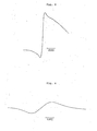
- Figs. 3 to 7 are the first differential of the absorption spectra of electron spin resonance that were obtained for the carbonaceous materials prepared in several of the Examples and Comparative Examples that are given later in this specification.
- The electrode material in accordance with the present invention has a pseudo-graphite structure obtained by the pyrolysis of an organic compound capable of forming the graphite structure.
- The organic compound capable of forming the graphite structure as used in the present invention is such an organic compound that its carbon-carbon bonds will change to a benzene ring structure upon reactions such as decomposition and condensation and that a continuous one- and two-dimensional bonding of such benzene rings forms a plurality of stacked polycyclic aromatic planes.
- Examples of such organic compounds are listed below. (A) Condensed polycyclic hydrocarbon compounds or polycyclic heterocyclic compounds:
- Condensed polycyclic hydrocarbon compounds are such that at least two monocyclic hydrocarbon compounds consisting of a three- or more membered ring-are condensed together. Derivatives of such condensed products may also be used.
- Polycyclic heterocyclic compounds are such that at least two monocyclic heterocyclic compounds consisting of a three- or more membered ring are condensed together or at least one such monocyclic heterocyclic compound is condensed with at least one monocyclic hydrocarbon compound consisting of a three- or more membered ring. Derivatives of such condensed products may also be used.
- Specific examples of the condensed polycyclic hydrocarbon compounds are naphthalene, chrysene, pyrene, peryl- ene, naphthoanthrene, terylene, pyranthrene, dibenzo(b,h)-chrysene, coronene, benzo(a)coronene, pentacene, ovalene and dibenzoperopyrene, as well as derivatives thereof. Specific examples of the polycyclic heterocyclic compounds are isoquinoline, phenazine and phthalazine, as well as derivatives thereof.
- Preferred compounds are selected from the following group.
- 1,2,4,5-substituted benzenes, naphthalene, isoquinoline, 1,4,5,8-substituted phthalazines, 1,4,9,10- or 1,5,9, 10-substituted anthracenes, 1,6,7,12-substituted chrysenes, 1,5,6,10-substituted pyrenes, 3,4,9,10-substituted perylenes, 1,5,6,11- or 5,6,10,11-substituted naphthoanthrene, 3,4,11,12-substituted terylenes, 1,14,7,8-dibenzoperopyrenes, 1,8,9,16-substituted 1,14,7,8-dibenzoperopyrenes, 1,7,8,16-, 1,8,9,16- or 5,6,13,14-substituted pyranthrenes, 1,7,8,15-, 8,9,14,15-, 1,8,9,15- or 7,8,14,15-substituted dibenzo(b,h)chrysenes, 1,6,7,12-substituted coronenes, 4,5,12,13-substituted benzo(a)coronenes, dibenzo(a,ℓ)penta- cenes, 4,5,13,14-substituted dibenzo(a,ℓ)pentacenes, 1,7,8,14-, 4,5,12,13- or 4,5,11,12-substituted ovalenes, quaterylene, 3,4,13,14-substituted quaterylenes, dibenzo-(def,mno)chrysene, and 3,4,9,10-substituted dibenzo-(def,mno)chrysenes.
- Illustrative substituents are organic compounds such as carboxylic acids, carboxylic acid anhydrides and carboxylic acid imides that contain a hetero atom and easily undergo homolytic fission and wherein two groups are bonded together with

- Preferred compounds of group (A) are selected from the following group: benzene-l,2,4,5-tetracarboxylic acid, benzene-1,2,4,5-tetracarboxylic acid- dianhydride, and benzene-1,2,4,5-tetracarboxylic acid diimide; naphthalene; isoquinoline; phthalazine-l,4,5,8-tetracarboxylic acid, phthalazine-1,4,5,8-tetracarboxylic acid dianhydride, and phthalazine-1,4,5,8-tetracarboxylic acid diimide; perylene; perylene-3,4,9,10-tetracarboxylic acid, perylene-3,4,9,10-tetracarboxylic acid dianhydride, and perylene-3,4,9,10-tetracarboxylic acid diimide; terylene; terylene-3,4,11,12-tetracarboxylic acid, terylene-3,4,11,12-tetracarboxylic acid dianhydride, and terylene-3,4,11,12-tetracarboxylic acid diimide; pyrene; pyrene-1,5,6,10-tetracarboxylic acid and pyrene-1,5,6,10-tetracarboxylic acid, and pyrene-1,5,6,10-tetracarboxylic acid diimide; dibenzo(def,mno)chrysene; dibenzo(def,mno)chrysene-3,4,9,10-tetracarboxylic acid, dibenzo(def,mno)chrysene-3,4,9,10-tetracarboxylic acid dianhydride, and dibenzo(def,mno)chrysene-3,4,9,10-tetracarboxylic acid diimide; coronene; and coronene-1,5,7,12-tetracarboxylic acid, coronene-1,6,7,12-tetracarboxylic acid dianhydride, and coronene-1,6,7,12-tetracarboxylic acid diimide.
- These compounds may have their carbon skeleton substituted by a halogen and such halogenated compounds may also be used.
- Linear novolak resins may be prepared by polycondensation of aldehyde compounds with mono-substituted phenols having a substituent on the ortho- or para-position.
- mono-substituted phenols having a substituent on the ortho- or para-position are represented by the following formula (1) or (2):

- Examples of the substituent X are alkyl groups such as methyl and nonyl, or halogens such as chlorine.
- Illustrative aldehyde compounds are formaldehyde, paraformaldehyde, trioxane, acetaldehyde, furfural and acrolein. Formaldehyde, paraformaldehyde and trioxane are particularly preferred.
- The mono-substituted phenols and aldehyde compounds are polycondensed in the presence of an acidic catalyst selected from among mineral acids such as hydrochloric acid, nitric acid, sulfuric acid, phosphoric acid and perchloric acid, as well as from among organic acids such as p-toluenesulfonic acid and oxalic acid.
- In order to prepare high-molecular weight linear novolak resins from the mono-substituted phenols and aldehyde compounds using the acidic catalyst, the proper process conditions must be selected depending upon the specific case.
- The methods for obtaining high-molecular weight, linear novolak resins are known. For example, W.J. Burke et al. reported in Journal of Polymer Science, 20, 75-88 (1956) that a high-molecular weight novolak type p-chlorophenolic resin could be obtained by polycondensing p-chlorophenol with formaldehyde. Hideo Matsuzaki reported in Kogyo Kagaku Zasshi (J. Chem. Soc. Japan, Ind. Chem. Sec.), 66, 95-99 (1963) the polycondensation of phenol and paraformaldehyde in the presence of p-toluenesulfonic acid as a catalyst.
- High-molecular weight ortho-cresol novolak resin and a process for producing the same are disclosed in Japanese Patent Application (OPI) No. 57-113. When an ortho-cresol novolak resin having a number average molecular weight of 550 is reacted with 37% formalin in toluene (solvent) in the presence of nitric acid at 175°C under superatmospheric pressure, a linear high-molecular weight (number av. mol. wt. = 2,010) ortho-cresol novolak resin that is soluble in dimethylacetamide is obtained.
- A high-molecular weight ortho- and para-cresol copolymerized novolak resin and a process for producing the same are described in Unexamined Published -Patent Application No. 56-92908. When an ortho-cresol novolak resin having a number average molecular weight of 550 is reacted with 2,6-dimethylol-p-cresol in ortho-dichlorobenzene (solvent) at 175°C in the presence of nitric acid, a linear, high-molecular weight (number av. mol. wt. = 1,930) ortho-and para-cresol copolymerized resin that is soluble in dimethylacetamide is obtained.
- Preferred linear high-molecular weight ortho-cresol novolak resins= or ortho- and para-cresol random copolymerized novolak resins may be prepared by the following novel process, in which ortho-cresol or a mixture of ortho-cresol and para-cresol is polymerized with formaldehyde, paraformaldehyde or trioxane in a polar organic solvent (i.e., alkyl alcohol or alkylcarboxylic acid) in the presence of an acid catalyst. In accordance with this method, novolak resins having fairly high molecular weights ranging from 2,100 to 5,000 in terms of the number average molecular weight are obtained.
- The linear high-molecular weight novolak resins prepared by the methods described above generally have number average molecular weights of 1,000 or more as determined by VPO (vapor pressure osmometry), preferably, 1,200 or more, more preferably 1,500 or more, and most preferably 2,000 or more.
- The term "linear high-molecular weight novolak resin" means those novolak resins which are soluble in - one of dimethylactamide, tetrahydrofuran and dioxane and which are substantially free from a gel component. Therefore, even novolak resins that have a small content of branched or network structure may be employed so long as they satisfy the requirement for solubility in the solvents listed above.
- In order to meet such requirements as the need to provide a shaped product having a certain amount of physical strength, the linear high-molecular weight novolak resin used in the present invention preferably contains a curing agent which helps its curing to varying degrees before it is pyrolyzed to form a polymeric conjugate. Suitable agents that may be used for the purpose of curing the linear high-molecular weight novolak resins include aldehyde compounds such as formaldehyde, paraformaldehyde, acetaldehyde and furfural, and other known cross-linking agents such as hexamethylene tetramine and trimethylol phosphine oxide.
- The linear high-molecular weight novolak resins may be cured by reaction with a resol - obtained by reacting phenol with an aldehyde compound in the presence of an alkali catalyst.
- Other usable curing agents are compounds having an epoxy group, such as epoxy resins.
- The amount of curing agent used varies with its type. If aldehyde compounds or epoxy compounds are used as the curing agent, their amounts are selected from the range up to 2.5 moles of the aldehyde compound or epoxy group per mole of the phenolic OH group in the linear high-molecular weight novolak resin. If hexamethylenetetramine or resol is used as the curing agent, their amounts are selected from the range up to 60 wt% of the linear high-molecular weight novolak resin.'
- Curing accelerators such as benzyldimethylamine, imidazoles, tris-dimethylaminomethyl phenol and BF3-piperidine salts, as well as a variety of fillers may optionally be used together with the curing agents.
- Examples of the poly(haloacrylnitrile) are poly(α-haloacrylnitrile) and poly(β-haloacrylnitrile), which are respectively prepared by polymerizing a-haloacrylnitrile and β-haloacrylnitrile. Homopolymers are useful but copolymers containing small proportions of comonomers may be used. Suitable comonomers include those which contain a nitrile group such as acrylonitrile, and vinyl halide compounds such as vinyl fluoride. The a-haloacrylonitrile and β-haloacrylonitrile are monomers that are respectively represented by the following formulae (3) and (4):


- The poly(α-haloacrylonitrile) and poly(β-haloacrylonitrile) are usually obtained by radical polymerization of a-haloacrylonitrile and β-haloacrylonitrile, respectively. A copolymer of a-haloacrylonitrile and β-haloacrylonitrile may also be used in the present invention.
- The poly(halodicyanoethylene) is obtained by polymerizing a halocyanoethylene and includes a homopolymer of halodicyanoethylene, as well as a copolymer of halodicyanoethylene and a small amount of a comonomer. The halodicyanoethylene is a monomer represented by formula (5):

- The poly(cyanoacetylene) and poly(dicyanoacetylene) are polymers of cyanoacetylene and dicyanoacetylene which are respectively represented by formulae (6) and (7). Homopolymers are preferred but copolymers with small fractions of comonomers may be used.


- The electrode material is obtained by the pyrolysis of one or more polymers selected from among the above-mentioned poly(α-haloacrylonitrile), poly(β-haloacryloniarile), poly-(halodicyanoethylene), poly(cyanoacetylene) and poly(dicyanoacetylene).
- In a preferred embodiment, the poly(α-haloacrylonitrile), poly(β-haloacrylonitrile) and poly(halodicyanoethylene) may be pyrolyzed after they are subjected to the reaction of removal of hydrogen halide by treatment with a tertiary amine compound such as pyridine, DBU (1,8-diazabi- cyclo[4,3,0]undecene-7) or triethylamine, a phase transfer catalyst such as benzene-trimethyl ammonium hydroxide; sodium amide (used in liquid ammonia), alkali hydroxide (used at high temperatures and pressure), potassium butoxide, butyl lithium, the combination of an aqueous alkali solution and an amine compound, and a crown ether.
- Poly(phenylene) and poly(substituted phenylene) may be synthesized by several known methods. See, for example, "A Course in the Theory of Polymerization Reactions", 12, New Polymerization Reactions, ed. by T. Saegusa, p. 31, ff.
- Usually, these polymers are obtained by subjecting benzene or a substituted benzene to oxidative cationic polymerization in the presence of a Lewis acid-oxidant system such as AlCl3-CuCl2·
- A preferred method for the synthesis of a high-molecular weight polyparaphenylene is disclosed by Marvel et al. in J. American Chemical Society, 81, 448 ff. (1959). This method consists of polymerizing 1,3-cyclohexadiene in the presence of a Ziegler catalyst such as Ti(OC4H9)4-Al(i-G4H9)3 or a cationic catalyst such as BF3, followed by treatment with a dehydrogenating agent such as chloranil to make the desired poly(paraphenylene).
- The poly(phenylene) and poly(substituted phenylene) used in the present invention have an average degree of polymerization (n) of at least 5, preferably at least 7, more preferably at least 10. However, poly(phenylene) having excessively high molecular weights are neither soluble or meltable and defy exact measurement of its molecular weight. The poly(phenylene) and poly(substituted phenylene) that are insoluble in solvents and which hence defy exact measurement of their molecular weights will be regarded as having degrees of polymerization of 7 or more.
- Preferred poly(phenylene) is poly(paraphenylene) since a product with an adequately high molecular weight can be obtained fairly easily and at low cost.
- The organic compounds capable of forming the graphite structure are pyrolyzed either in vacuum or under an inert gas (e.g., nitrogen or argon) stream or an oxidizing gas (e.g., air) stream or a mixture of such streams. Usually, the organic compounds are pyrolyzed in vacuum or under an inert gas stream.
- The mechanism of the pyrolysis is hereunder described with reference to naphthalene-l,4,5,8-tetracarboxylic acid dianhydride of group (A):


- When (A) is heated with a thermal energy greater than the dissociation energy necessary to break the bond between the skeletal carbon and an- adjacent hydrogen atom or a substituent, carbon radicals (B) are formed predominantly by homolytic cleavage. A chain of carbon radicals is cyclized to provide a higher molecular weight and the process of graphitization occurs that is characterized by the development of polycyclic aromatic planes. In the initial stage of graphitization, benzene rings are bound together one-dimensionally to form a one-dimensional graphite structure (C). Subsequently, the benzene rings start to bind with one another two-dimensionally, and gradually expanding polycyclic aromatic planes begin to stack in layers to form a two-dimensional graphite structure (D).
- The same phenomenon will occur in the pyrolysis of other organic compounds capable of forming the graphite structure; the one-dimensional graphite structure (C) forms as a result of thermal decomposition or condensation, and subsequently a structure similar to the two-dimensional graphite structure (D) forms.
- With further progress of carbonization, more benzene rings are bound two-dimensionally and adequately expanded polycyclic aromatic planes stack one on another in an orderly manner to form the ordinary graphite. In accordance with the present invention, all structures that lead to the final graphite are collectively referred to as the pseudo-graphite structure. The organic compounds capable of forming the graphite structure may be carbonized not only by application of thermal energy but also by irradiation by light energy greater than the dissociation energy, as well as by irradiation by accelerated charged particles such as Br+ or Ar+ or by plasma irradiation. The graphitization reaction of the organic compounds may proceed in any one of the three states, molten, solid and gaseous. The carbonaceous material thus obtained in accordance with the present invention is very stable and will hot deteriorate upon standing in air at room temperature.
- The pseudo-graphite structure in accordance with the present invention can be determined both qualitatively and quantitatively by X-ray wide angle diffraction. The ordinary graphite shows a sharp diffraction peak corresponding to a (002) plane at about 2θ = 26°. In the initial stage of graphitization of the organic compounds capable of forming the graphite structure, no diffraction peak corresponding to the (002) plane does not appear. The one-dimensional graphite obtained by further pyrolysis has a very broad diffraction peak corresponding to the (002) plane and its intensity is low. As two-dimensional polycyclic aromatic planes begin to stack one after another, the diffraction peak corresponding to the (002) plane gradually becomes sharp and its intensity increases. The pseudo-graphite structure which characterizes the carbonaceous material of the present invention is such that the spacing of (002) 0 planes, d002, is at least 3.37 A and the crystallite size in the direction of c axis, Lc, is not more than 220 A. Preferably, d002 is at least 3.40 A and not more than 3.75 A, whereas Lc is at least 7.0 A and not more than 150 A. 0 More preferably, d002 is at least 3.41 A and not more than O O O 3.70 A whereas Lc is at least 7.0 A and not more than 70 A.
- The pseudo-graphite structure in accordance with the present invention is also determined quantitatively by x-ray wide-angle diffraction such that the distance a0 (=2d110) twice the spacing of (110) planes, dllO, is 0 0 preferably at least 2.37 A and not more than 2.47 A, more o o preferably at least 2.37 A and not more than 2.46 A. In the preferred pseudo-graphite structure, the crystallite size in o the direction of a axis, La, is not more than 200 A. More preferably, La is at least 7.0 A and not more than 150 A, with the range of 10 to 80 A being particularly preferred.
- The electron state of the carbonaceous material in accordance with the present invention is determined quantitatively by electron spin resonance spectroscopy. More specifically, the line width (ΔHpp in gauss) between peaks in the first differential of the absorption spectrum of electron spin resonance as shown in Fig. 1 is used as the factor for determining the electron state of the carbonaceous material. Fig. 2 shews the concept of the behavior of ΔHpp as a function of the carbonization temperature for the condensed polycyclic hydrocarbon compound and polycyclic heterocyclic compound used as the organic compound capable of forming the graphite structure. According to the finding of the present inventors, the behavior of AHpp can be divided into six regions, A to F. Region A corresponds to the initial stage of carbonization and the value of AHpp is smaller than 7 (indicating a very sharp peak in the spectrum) and either remains constant or decreases slightly with the increasing temperature. In region B, ΔHpp increases gradually and is in the range of 7≤Hpp≤10. Region B may contain an extension of region A having a sharp peak (AHpp<7), as indicated by the dashed line. In region C, ΔHpp increases rapidly and is in the range of 10<ΔHpp≤1000. Region C may also contain an extension of region A having a sharp peak (ΔHpp<7), as indicated by the dashed line. In region D, a hyperbroad peak exists in the spectrum and ΔHpp>1000. In some cases, it is apparently impossible to detect the absorption spectrum in region D. The exact reason for this is not clear but the existence of a hyperbroad peak would be the primary cause. In region E, AHpp decreases and is in the range of T≤ΔHpp≤1000. In region F, a sharp peak appears again and ΔHpp is smaller than 7. The horizonfal axis of the graph in Fig. 2 indicates the graphitization temperature, but it should be understood that given the same graphitization temperature, ΔHpg may vary and belong to different regions depending upon other conditions for graphitization such as the rate of temperature increase and the period for which said graphitization temperature is retained. In an extreme case, there may exist no distinct separation between each region. It is not clear what the electron states ranging from regions A to F mean in physical terms. Most probably, the peaks in -regions A and B may be explained by unpaired electrons that exist stably in the long conjugated chain. Conduction electrons would be responsible for the peaks in regions C, D, E and F. Conduction electrons may make some contribution to the peak in region B. For the purpose of the present invention, the electron states in regions C, D and E having ΔHpp not smaller than 10 gauss are necessary. Electron states having AHpp of at least 12 gauss are preferred, with AHpp of at least 15 gauss being particularly preferred.
- When organic polymeric compounds such as poly(a-haloacrylonitrile) or the reaction product of a linear high-molecular weight novolak resin and a curing agent are used as the organic compounds capable of forming the graphite structure, the behavior of their values of AHpp as a function of the graphitization temperature is not necessarily the same as shown in Fig. 2. But even in this case, the line width, ΔHpp, between peaks in the first diffrential of the absorption spectrum of electron spin resonance must be at least 10 gauss.
- Some carbonaceous materials prepared in accordance with the present invention may exhibit two or more signals in the first differential of the absorption spectrum of electron spin resonance, and even such materials are included within the scope of the present invention if at least one of the signals have an interpeak line width, ΔHpp, of 10 gauss or more.
- Carbonaceous materials may also be obtained that have no clearly distinguishable signals in the first differential of the absorption spectrum electron spin resonance; such materials are also included within the scope of the present invention if there exists no signal having an interpeak line width, ΔHpp, of less than 10.
- The pyrolysis temperature relates to the degree of growth of the intended polymer conjugate. In order to - achieve a balance between the ease of doping electrolyte ions, the stability of doped charges and the electrical conductivity of undoped polymer conjugate, the proper pyrolysis temperature is selected preferably from the range of 300 to 3,000°C, more preferably from the range of 400 to 2,500°C.
- The pyrolysis period is generally at least 5 minutes and the preferred range-is from 10 minutes to 20 hours. The range of 20 minutes to 10 hours is particularly preferred.
- By providing a larger specific surface area for the electrode material formed, a battery capable of producing a higher maximum power density can be obtained. Therefore, in order to ensure a high maximum power density, the shaped article of the electrode material formed or a shaped article containing such electrode material preferably has a specific surface area of at least 10 m2/g, more preferably - at least 50 m2/g, and most preferably at least 100 m2/g. This object can be attained by pyrolyzing the organic compound either under an oxidizing gas (water vapor,- or CO2) stream or under a stream of a mixture of such oxidizing gas and an inert gas. Another effective way is to perform a preliminary pyrolysis under an inert gas stream, followed by another pyrolyzing step under an oxidizing gas stream or under a stream of a mixture of an oxidizing gas and an inert gas.
- A larger specific surface area may also be obtained by pyrolyzing a porous shaped article of,the reaction product of the linear high-molecular weight novolak resin and the curing agent.
- The organic compound to be pyrolyzed is shaped to a variety of forms such as fibers, powders, granules, films, sheets and felt. Polymer conjugates prepared by pyrolyzing films, sheets or felt of the organic compound such as the reaction product of the linear high-molecular weight novolak resin and curing agent may be immediately used as cell electrodes.
- Electrode materials in a fibrous, powder or granular form may be used as cell electrodes after they are shaped into the form of paper sheet or film by any of the known techniques.
- The carbonaceous material obtained by pyrolyzing the organic compound may be independently used as the electrode material of the present invention. If desired, such carbonaceous material may be supplemented with or supported on, - a conductive material (e.g., carbon fibers) , an insulating material or a reinforcing material. In this latter case, the amount of the electrode material in the shaped article is not limited to any particular value, but preferably, the electrode material is present in an amount of at least 50 wt%, with the range of 70 wt% and upward being particularly preferred.
- A variety of carbonaceous materials, metallic materials and conductive ceramics may be used as the conductive additives. Suitable insulating materials include ceramics such as Al203 and SiO2, and glassy materials such as borosilicate glass and silicate glass.
- The organic compound used in the present invention may be supported on the conductive additive, insulating material or reinforcing materials by various. methods. First, the organic compound is supported on the carrier by a suitable technique and the compound on the carrier is carbonized by heating. Suitable presupporting techniques include gasification at temperatures not higher than the thermal decomposition point of the compound, solubilization in a solvent and dispersion in the same. Secondly, the compound is first gasified by either evaporation or sublimation and then deposited on the carrier as graphitization proceeds. Thirdly, a molten compound is brought into contact with, or impregnated in, the carrier and then, is graphitized to make the compound on the carrier.
- The proportion of the carbonaceous material carried is not limited to any particular value, but the preferred range is from 0.1 to 99 wt%. The range of 1 to 97 wt% is particularly preferred.
- The electrode material of the present invention may be used as either positive or negative electrode or both. The electrode material is submerged in an electrolyte to make a primary or secondary battery. Any of the known electrolytes may be used and they include tetraalkylammonium salts (counter anions are perchlorate ion, phosphorus hexafluoride ion, thallium hexafluoride ion, arsenic hexafluoride ion, antimony hexafluoride ion, halide ions, nitrate ion, sulfate ion and rhenium tetraoxide ion), alkali metal salts, alkaline earth metal salts (counter ions are the same as listed above), as well as halides, perchlorates and nitrates of transition metals, rare earth elements and noble metals. Any of the solvents that are commonly used in conventional batteries may be used, and they include water, dimethyl sulfoxide, acetonitrile, propylene carbonate, 4- butyrolactone, formamide, tetrahydrofuran and 1,2-dimethoxyethane. The batteries fabricated by using the electrode material of the present invention as shown above are stable, produce high electromotive force, have high maximum-power and energy densities, and can be used with a variety of electrode shapes.
- The carbonaceous material in accordance with the present invention finds many other uses as electrical and electronic materials in solar cells, sensors, capacitors and conductors.
- The various parameters that characterize the carbonaceous material of the present invention are determined by the following respective methods.
- A powder of carbonaceous material (flaky carbonaceous material is reduced to a powder in an agate mortar) is packed into a sample cell together with ca. 15wt% of the powder of an internal standard substance, a high-purity silicon powder of the standard grade for X-ray analysis. A wide-angle X-ray reflection diffractometer scan is obtained with monochromatic CuKa radiation from a graphite monochrometer. Instead of making corrections associated with the Lorentz factor, polarization factor, absorption factor and atomic scattering factor, the following simple and convenient method is used. Draw a baseline for the scan curves corresponding to diffractions at (002) and (110) planes. Plot the substantial intensities as calculated from the baseline, obtaining corrected curves for (002) and (110) planes. Draw an angular axis at a height which is two- thirds of the height of the peak in each curve and obtain the midpoint of the line defined by the two points where a line parallel to that angular axis intersects the scan curve. Correct the angle of the midpoint by the internal standard to obtain a value twice the angle of diffraction. Substitute this value and the wavelength of CuKα radiation, λ, into the following two equations of Bragg's law:


- wherein λ: 1.5418 A
- θ: the angle of diffraction corresponding to d002 or dllO.
- Obtain the half-width β at a point half the height of the peak in each of the corrected scan curves prepared in (1), and substitute this value into the following equations:


- Various values may be taken for the shape factor K, but in the present invention, 0.90 is used. For the meanings of λ and 6, see (1).
- The first differential of the absorption spectrum of electron spin resonance was measured with JEOL JES-FE 1X ESR spectrometer in the X-band. A powder of carbonaceous material (flaky carbonaceous material is reduced to a powder in an agate mortar) is put into a capillary tube (ID: 1 mm) which is placed in an ESR tube (OD: 5 mm). The radiofrequency magnetic field is modulated by an amount of 6.3 gauss. All the procedures above are followed within air at 23°C. The value of ΔHpp is determined by comparison to a standard sample, Mn2+/MgO.
- A sample is dried in vacuum at 120°C for ca. 15 hours. Then, the sample is transferred onto a hot plate in a dry box and dried in vacuum at 100°C for 1 hour. A portion of the dried sample is put into an aluminum cup in an argon atmosphere, and the carbon content is determined from the weight of C02 gas evolved as a result of combustion whereas the hydrogen content is determined from the weight of H20 also evolved by combustion. In the Examples that follow, an elemental analyzer of Perkin-Elmer Model 240 C was used.
- The following Examples and Comparative Examples are provided for further illustration of the claimed electrode material and should not be construed as limiting.
- A powder of naphthalene-l,4,5,8-tetracarboxylic acid dianhydride was put in a magnetic crucible and preliminarily graphitized by heating at one atmosphere in N2 gas stream under the following conditions: the temperature was elevated to TR = 375°C at a rate of Vt = 10°C/min. and that temperature was retained for Ht = 30 minutes.
- The powder was cooled to room temperature and again heated in N2 stream to TR = 460°C .at a rate Vt = 10°C/min., followed by holding for Ht = 30 minutes. The first differential of the absorption spectrum of electron spin resonance .for the resulting flaky carbonaceous material is shown in Fig. 3, from which one can see that AHpp = 11.2 gauss. The intensity of a diffraction curve for the same material was 0 0 weak; d002 = 3.67 A and Lc = 13.0 A. A portion (1.8 mg) of the carbonaceous material was wrapped with a platinum screen to make a positive electrode. This positive electrode and a metallic lithium negative electrode were submerged in an electrolyte (1.0 M solution of lithium perchlorate in propylene carbonate) to make a battery.
- The battery was charged at 59 pA (5 µA/mg) for 333 minutes until 1.180 coulombs of electric charge (0.1 C/mg) was stored. The charged battery had an open circuit voltage Voc of 4.54 volts and was capable of producing high electromotive force. After charging, the battery was left to stand in the open circuit state; the self-discharge at 10th hour was 3.5%, indicating high stability of the battery.
- A powder of the same material as used in Example 1-1 was preliminarily graphitized by heating in N2 stream under the following conditions: Vt = 10°C/min., TR = 375°C and Ht = 30 min. The powder was cooled to room temperature and graphitized under the following conditions: Vt = 10°C/min., TR = 570°C and Ht = 30 min. A flaky carbonaceous material was obtained; ΔHpp = 110.4 gauss. The intensity of a dif- fraction curve for this material was weak: d002 = 3.67 A and Lc = 13.1 A. A battery was fabricated as in Example 1-1 using 16.9 mg of this carbonaceous material as a positive electrode. The battery was charged for 333 minutes at 84 µA (5 µA/mg) until the charge stored was 1.690 C (0.1 C/mg). The charged battery had Voc of 4.50 volts and was capable of producing high electromotive force. After charging, the battery was left to stand in the open circuit state; the self-discharge at 10th hour was 4.6%, indicating high stability of the battery.
- A fiberglass filter (GA 200 of Toyo Roshi Kaisha Ltd.) was used as a carrier. A powder (ca. 100 mg) of the same material as used in Example 1-1 was put in a magnetic crucible and a rectangle of the fiberglass filter (26.6 mg) was buried in the powder. The powder was preliminarily graphitized by heating in N2 stream under the following conditions: Vt = 10°C/min., TR = 375°C and Ht = 30 minutes. The powder was deposited onto the fiberglass filter by sublimation. The powder was cooled to room temperature and graphitized by another heating in N2 stream under the following conditions: Vt = 10°C/min., TR = 520°C and Ht = 30 min. As a result of carrying the carbonaceous material, the fiberglass filter increased in weight to 31.8 mg. The carbonaceous material was uniformly carried on the filter in a proportion of 16.4%. The carried carbonaceous material had AHpp = 11.7 gauss. The intensity of a diffraction curve o o for this material was weak; d002 = 3.62 A and Lc = 13.2 A. The respective values of ΔHpp, d002 and Lc were determined using a pure carbonaceous material obtained by graphitization in magnetic crucible under the same conditions as used above. A battery was fabricated as in Example 1-1 using 31.8 mg of the fiberglass filter (corresponding to 5.2 mg of the pure carbonaceous material) as a positive electrode. The battery was charged for 250 minutes at 104 µA (20 µA/mg) until the charge stored was 1.645 C (0.32 C/mg). The charged battery had Voc of 4.88 volts and was capable of producing high electromotive force. The charged battery had a high theoretical energy density, 370 W.h/kg.
- A powder of the-same material as used in Example 1-1 was graphitized by heating in N2 stream under the following conditions: Vt = 10°C/min., TR = 375°C and Ht = 30 min. A first differential of the absorption spectrum of electron spin resonance for the resulting powder of carbonaceous material is shown in Fig. 4, from which one can see that ΔHpp = 6.7 gauss. A battery was fabricated as in Example 1-1 using 23.7 mg of the carbonaceous material as a positive electrode. This battery was charged for 333 minutes at 118 µA (5 µA/mg) until the charge stored was 2.370 C (0.1 C/mg). With the progress of charging, the potential increased rapidly to give Voc which was as high as 5.38 volts, but when the charging was completed, a momentary voltage drop occurred. Additionally, the electrolyte turned yellow as the charging proceeded. Because of these problems, i.e., high overvoltage and decomposition of the electrolyte, the carbonaceous material prepared in Comparative Example 1-1 was not suitable for as an active material for battery electrodes.
- A powder of perylene-3,4,9,10-tetracarboxylic acid dianhydride was graphitized by heating in N2 stream under the following conditions: Vt = 10°C/min., T R = 570°C and Ht = 60 min. The first differential of the absorption spectrum of electron spin resonance for the resulting powder of carbonaceous material is shown in Fig. 5, from which one can see that AHpp = 105.1 gauss. The intensity of a diffraction 0 curve for the same material was weak; d002 = 3.61 A and o Lc = 13.3 A. Two portions (7.4 mg each) of the carbonaceous material was individually wrapped with a platinum screen to make positive and negative electrodes, which were separated by a fiberglass filter. The outer surfaces of the electrodes were also covered with a fiberglass filter, which was fixed by wrapping Teflon tape partly around the electrodes.
- A battery was fabricated by submerging both electrodes in an electrolyte which was composed of a 1.0 M solution- of lithium perchlorate in propylene carbonate. This battery was charged for 667 minutes at 37 µA (5 µA/mg) until the charge stored was 1.480 C (0.2 C/mg). The charged battery had Voc = 3.25 volts and was capable of producing high electromotive force. Immediately after completion of the charging, the battery was shorted to produce a short ciruci-t current Isc of 294 mA. The maximum power density Pmax was 14.5 kW per kg of the sum of the weight of the active material for both electrodes and that of doped ions.
- A powder of the same material as used in Example 2-1 was graphitized by heating in N2 stream under the following conditions: Vt = 10°C/min., TR = 530°C and Ht = 60 min. The resulting carbonaceous material had Hpp of 5.7 gauss. A battery was fabricated as in Example 2-1 by using two portions (10.0 mg each) of the carbonaceous material as positive and negative electrodes. The battery was charged for 667 minutes at 50 µA (5 µA/mg) until the charge stored was 2.000 C (0.2 C/mg). The potential between the electrodes increased rapidly when a charge of about 1.26 C had been stored. Because of this excessively high overvoltage, the carbonaceous material prepared in Comparative Example 2-1 was unsuitable for use as an active material for battery electrodes.
- 'A powder of the same material as used in Example 2-1 was graphitized by heating in N2 stream under the following conditions: Vt = 10°C/min., TR = 920°C and Ht = 60 min. The first differential of the absorption spectrum of electron spin resonance for the resulting powder of carbonaceous material is shown in Fig. 6, from which one can see that ΔHpp = 1294 gauss. The intensity of a diffraction curve for the carbonaceous material was weak; d002 = 3.62 A and Lc = o 13.8 A. A battery was fabricated as in Example 2-1 by using two portions (10.2 mg each) of the carbonaceous material as positive and negative electrodes. The battery was charged for 667 minutes at 51 µA (5 µA/mg) until the charge stored was 2.040 C (0.2 C/mg). The charged battery had Voc = 3.60 volts and was capable of producing high electromotive force. The short circuit current Isc of the battery was 298mA and the maximum powder density Pmax was as high as 11.7 kW/kg.
- A powder of the same material as used in Example 2-1 was preliminarily graphitized by heating in N2 stream under the following conditions: Vt = 10°C/min., TR = 920°C and Ht = 60 min. The powder was cooled to room temperature and graphitized by rapid heating in Ar stream to TR = 1,600°C at which temperature the powder was held for Ht = 60 min. The first differential of the absorption spectrum of electron spin resonance for the resulting powder of carbonaceous material is shown in Fig. 7, from which one can see that Hpp = 81.9 0 gauss. An X-ray diffractiometry gave d002 = 3.47 A and 0 Lc = 50.0 A. A battery was fabricated as in Example 2-1 by using two portions (13.4 mg each) of the carbonaceous material as positive and negative electrodes. The battery was charged for 667 minutes at 67 µA (5 µA/mg) until the charge stored was 2.680 C (0.2 C/mg ) . The charged battery had Voc = 3.80 volts and was capable of producing high electromotive force. The battery had Isc = 380 mA and Pmax = 12.1 kW/kg.
- Ortho-cresol (108 g), para-formaldehyde (32 g), ethyl cellosolve (240 g) and sulfuric acid (10 g) were put into a reactor and agitated at 115°C. for 4 hours. After completion of the reaction, the mixture was neutralized with 17 g of NaHC03 and 30 g of water. The mixture was then charged into 2,000 ml of rapidly agitated water. The precipitating resin component was separated by filtration and dried to obtain 115 g of a resin. This resin was soluble in methanol, ethanol, butanol, octanol, methyl cellosolve, ethyl cellosolve, tetrahydrofuran, dioxane, acetone, methyl ethyl ketone and ethyl acetate, and had no gel component. The resin was insaluble in benzene, toluene, xylene, chloroform and carbon tetrachloride. The resin had a number average molecular weight of -2,600 as measured by VPO (at 40°C in methyl ethyl ketone), and a softening point of 155°C as determined by microscopic observation. IR and NMR analyses showed that this resin was a linear novolak resin consisting of cresol chains bound by methylene groups.
- A mixture of the linear high-molecular weight novolak resin (2.25 g) and hexamine (0.25 g) was dissolved in ethanol, which was then distilled off. The residual mixture of novolak resin and hexamine was put into a glass container and heated in nitrogen gas at 220°C for 3 hours. The heat-treated mixture of novolak resin and hexamine swelled, rather than dissolved, in ethanol. The swollen novolak resin/hexamine mixture was compressed at 190°C and 200 kg/cm2 to make a strip 2 cm wide, 5 cm long and 1 mm thick.
- The strip was set in an electric furnace and heated in a nitrogen stream to 1,200°C at a rate of 20°C/min. Thereafter, the strip was held at 1,200°C for 1 hour in a nitrogen stream, producing a black strip of carbonaceous material weighing 50 mg.
- Elemental analysis showed that this carbonaceous material had a H/C atomic ratio of 0.14. X-ray wide-angle o diffractiometry gave the following data: d002 =.3.80 A, Lc = 11 A, a0 (2d110) = 2.38 A and La = 16 A.
- The line width (AHpp) between peaks in the first differential of the absorption spectrum of electron spin resonance was 50 gauss.
- Fifty milligrams of the strip of carbonaceous material prepared in (3) was wrapped with a nickel screen (55 mesh) to make one electrode. Metallic lithium was also wrapped with a nickel screen (55 mesh) to make the other electrode. The two electrodes as separated by a fiberglass filter 0.5 mm thick were submerged in an electrolyte made of 1.0 mol/1,000 ml of LiCIO4 in propylene carbonate. The two electrodes were interconnected by a nickel wire lead. The resulting battery was charged by passing a constant 0.12 mA current from a potentiostat/galvanostat (HA-501 of Hokuto Denko K-K.), with the negative electrode connected to the electrode made of metallic lithium wrapped with the nickel screen and the positive electrode connected to the electrode composed of the strip of carbonaceous material also wrapped with the nickel screen. The charging was continued until a coulometer read a value of 6.0 C.
- Immediately after the charging, the battery was discharged with a constant-50 kΩ resistance connected between the electrodes, until the open circuit voltage between each electrode dropped to 2.5 volts. The quantity of discharge electricity was 5.2 C. The same constant resistance test was conducted after leaving charged the battery for 3 days. When the battery was discharged until the open circuit voltage became 2.5 volts, the 4.2 C of electricity was found to have been discharged.
- A pressed strip of a heat-treated mixture of linear high-molecular weight novolak resin and hexamine was prepared as in Example 3. This strip was set in an electric furnace and heated in a nitrogen stream to 2,000°C at a rate of 20°C/min. Thereafter, the strip was held at 2,000°C for 1 hour in a nitrogen stream, producing a black strip of carbonaceous material weighing 50 mg.
- Elemental analysis showed that this carbonaceous material had a H/C atomic ratio of 0.04. X-ray wide-angle diffractiometry gave the following data: d002 = 3.61 A, 0 Lc = 14 A, a0 (2d110) = 2.41 A and La = 22 A.
- The line width (AHpp) between peaks in the first differential of the absorption spectrum of electron spin resonance was 200 gauss.
- A battery was fabricated as in Example 3 except that metallic nickel was replaced by 50 mg of the strip of carbonaceous material that was wrapped with'a nickel screen (55 mesh). The so fabricated battery was charged as in Example 3 by passing a constant 0.12 mA current between the two electrodes until a coulometer read a value of 6.0 C.
- Immediately after the charging, the battery was discharged with a constant 50 kΩ resistance connected between the electrodes, until the open circuit voltage between each electrode dropped to 1.0 volts. The quantity of discharged electricity was 5.3 C. The same constant resistance test was conducted after leaving the charged battery for 3 days. When the battery was discharged until the open circuit voltage became 1.0 volts, the 4.0 C of electricity was found to have been discharged.
- Phenol was reacted with formaldehyde (molar ratio of formaldehyde to phenol: 0.82) in the presence of an acid catalyst to form a novolak resin having a number average molecular weight of 600. A mixture of the novolak resin (2.25 g) and hexamine (0.25 g) was dissolved in ethanol, and the resulting solution was cast onto a glass plate. The web was dried with air to remove ethanol, and then cured at 120°C. The cured sheeting (1 mm thick) was heated in a nitrogen stream to 500°C at a rate of 5°C/min: and held at 500°C for 1 hour, producing a sheet of carbonaceous material (50 mg).
- X-ray wide-angle diffractiometry of the carbonaceous material gave a very broad peak corresponding to a (002) plane. The line width (AHpp) between peaks in the first differential of the absorption spectrum of electron spin resonance was 5 gauss.
- A battery was fabricated as in Example 3 except that 50 mg of the strip of carbonaceous material was replaced by an equal amount of the sheet of carbonaceous material. The so fabricated battery was charged as in Example-3 by passing a constant (0.12 mA) current between the two electrodes until a coulometer read a value of 6.0 C.
- Immediately after the charging, the battery was discharged through a constant 50 kn resistance connected between the electrodes until the open circuit voltage between each electrode dropped to 2.5 volts. The quantity of discharged electricity was 3.1 C. The same constant resistance test was conducted after leaving the charged battery for 3 days. When the battery was discharged until the open circuit voltage became 2.5 volts, the 2.2 C of electricity was found to have been discharged.
- Table 1 shows the charge efficiencies (percent ratio of discharged electricity to charged electricity) of the batteries. prepared in Examples 3 and 4 as compared with those of the battery made in Comparative Example 3. The batteries of Examples 3 and 4 were superior to the battery of Comparative Example 3 whether the discharge was conducted immediately after or three days after the charging.

- Poly(a-fluoroacrylonitrile) was dissolved in acetone and the solution was cast onto a glass plate. The web was dried with air to provide a film 500 µm thick. The film was placed in a quartz glass tube and evacuated. The glass tube containing the film was set in an electric heater and heated in vacuum to 300°C at a rate of 10°C/min. The film was subsequently held at 300°C for 1 hour, producing a black substrate film. This film was heated in a nitrogen stream to 1,200°C at a rate of 20°C/min., and subsequently held at 1,200"C for 1 hour.
- Elemental analysis showed that the resulting film of carbonaceous material had a H/C atomic ratio of 0.18. X-ray wide-angle diffractiometry gave the following data: d002 = 3.51 A and Lc = 12 A. The first differential of the absorption spectrum of electron spin resonance for the carbonaceous material had two signals and the respective interpeak line widths were 20 gauss and 60 gauss.
- A battery was fabricated as in Example 3 except that 50 mg of the strip of carbonaceous material was replaced by 50 mg of the film of carbonaceous material prepared above. The battery so fabricated was charged as in Example 3 by passing a constant (0.10 mA) current between the two electrodes until a coulometer read a value of 5.0 C.
- Immediately after the charging, the battery was discharged through a constant 50 kΩ resistance connected between two electrodes. An electricity of 4.4 C had been discharged by the time the open circuit voltage of the battery dropped to 2.0 volts. Charge-discharge cycles were repeated, and in the 4th cycle, 4.5 C of electricity was discharged as compared with 5.0 C that had been charged. After the 5th charging, the battery was left to stand for 15 hours and discharged through a constant 50 kΩ resistance. An electricity of 3.8 C was discharged as compared with 5.0 C of charged electricity. The charge efficiencies of the lst, 4th and 5th charge-discharge cycles are shown in Table 2.
- A 500 µm-thick film of poly(a-fluoroacrylonitrile) was heat-treated in vacuum at 300°C as in Example 5, producing a black substrate film. The film was further heated in a nitrogen stream to 1,700°C at a rate of 20°C/min., and held at 1,700°C for 1 hour. The resulting film of carbonaceous material had a H/C atomic ratio of 0.05. X-ray wide-angle diffractiometry gave the following data: d002 = 3.45 A and Lc = 20 Å. The line width (AHpp) between peaks in the first differential of the absorption spectrum of electron spin resonance for the carbonaceous material was 930 gauss.
- A battery was fabricated as in Example 3 except that metallic lithium was replaced by 50 mg of the film of carbonaceous material which was wrapped with a 55-mesh nickel screen. The battery so fabricated was charged as in Example 3 by passing a constant 0.10 mA current until a coulometer read 5.0 C.
- Immediately after the charging, the battery was discharged with a constant 50 kΩ resistance connected between the two electrodes until the open circuit voltage between each electrode dropped to 1.0 volt. An electricity of 4.3 C had been discharged. Charge-discharge cycles were repeated, and in the 4th cycle, 4.4 C of electricity was discharged as compared with 5.0 C that had been charged. After the 5th charging, the battery was left to stand for 15 hours and discharged through a constant 50 kΩ resistance. An electricity of 3.8 C was discharged as compared with 5.0 C of charged electricity. The charge efficiencies of the lsz, 4th and 5th charge-discharge cycles are shown in Table 2.
- Pitch-base carbon fibers were set in an electric furnace and heated in a nitrogen stream to 3,000°C at a rate of 20°C/min. The fibers were then held in a nitrogen stream at 3,000°C for 1 hour. X-ray wide-angle diffractiometry of the resulting carbonaceous material gave the following data: a d002 = 3.35 A and Lc = 230 A. The line width (ΔHpp) between peaks in the first differential of the absorption spectrum of electron spin resonance was 5 gauss.
- A battery was fabricated as in Example 3 except that 50 mg of the strip of carbonaceous material was replaced by 50 mg of graphite carbonaceous material prepared above. The battery so fabricated was charged as in Example 3 by passing a constant 0.10 mA current between the electrodes until a coulometer read and electricity of 5.0 C.
- Immediately after the charging, the battery was discharged with a constant 50 kn resistance connected between the two electrodes. When the open circuit voltage between the electrodes dropped to 2.0 volts, an electricity of 0.71 C had been discharged. Charge-discharge cycles were repeated, and in the 4th cycle, 0.60 C of electricity was discharged as compared with 5.0 C that had been charged. After the 5th charging, the battery was left to stand for 15 hours and discharged through a constant 50 kΩ resistance. An electricity of 0.31 C was discharged as compared with 5.0 C of charged electricity. The charge efficiencies of the lst, 4th and 5th charge-discharge cycles are shown in

- As is clearly seen from the, above data, the batteries made in Examples -5 and 6 were superior to the battery of Comparative Example 4 in that the former exhibited higher charge efficiencies not only in the 1st and 4th charge-discharge cycles, but also in the 5th cycle wherein discharging was conducted 15 hours after charging.
- Benzene was subjected to oxidative cationic polymerization using a catalyst made of cuprous chloride and aluminum chloride. The resulting poly(paraghenylene) was not soluble in ordinary solvents such as benzene and toluene, and did not melt under heating up to 500°C.
- A powder of the poly(paraphenylene) was heated in an electric furnace in a nitrogen stream to 600°C at a rate of 10°C/min. The powder was subsequently held at 600°C in a nitrogen stream for 1 hour, producing a black pyrolyzed powder of poly(paraphenylene). Electron spin resonance spectroscopy of this material gave a signal having a g-value of 2.0011. The line width (AHpp) between peaks in the first differential of the absorption spectrum for that signal was 12.3 gauss.
- A portion (20 mg) of the pyrolyzed poly(paraphenylene) was wrapped with a 200-mesh nickel screen to make one electrode. The other electrode was made of 20 mg of metallic lithium. The two electrodes were separated by a fiberglass filter 0.5 mm thick.
- The two electrodes were interconnected by a nickel wire lead. The resulting battery was charged by passing a constant .0.20 mA current from a potentionstat/galvanostat (HA-501 of Hokuto Denko K.K.), with the positive electrode connected to the electrode made of the pyrolyzed poly(para- phenylene) and the negative electrode connected to the electrode composed of metallic lithium. The charging was continued until a coulometer read a value of 4.0 C.
- Immediately after the charging, the battery was discharged with a constant 1 kΩ resistance connected between the electrodes. An electricity of 3.12 C had been discharged before the voltage between the electrodes dropped to 1.5 volts.
- Charge-discharge cycles were repeated and tin the 7th cycle, 3.21 C of electricity was discharged as compared with 4.0 C that had been charged. After the 8th charging, the battery was left to stand for 15 hours and discharged through a constant 1-kΩ resistance. The discharged electricity was 2.52 C as compared with the charged 4.0 C.
Claims (11)
Applications Claiming Priority (6)
| Application Number | Priority Date | Filing Date | Title |
|---|---|---|---|
| JP59120499A JPS60264052A (en) | 1984-06-12 | 1984-06-12 | Organic polymer system electrode |
| JP120499/84 | 1984-06-12 | ||
| JP59230292A JPH0782836B2 (en) | 1984-11-02 | 1984-11-02 | Electrode material |
| JP230293/84 | 1984-11-02 | ||
| JP230292/84 | 1984-11-02 | ||
| JP59230293A JPS61111908A (en) | 1984-11-02 | 1984-11-02 | Material for electrode |
Publications (3)
| Publication Number | Publication Date |
|---|---|
| EP0165047A2 true EP0165047A2 (en) | 1985-12-18 |
| EP0165047A3 EP0165047A3 (en) | 1988-01-07 |
| EP0165047B1 EP0165047B1 (en) | 1997-10-15 |
Family
ID=27314062
Family Applications (1)
| Application Number | Title | Priority Date | Filing Date |
|---|---|---|---|
| EP85304139A Expired - Lifetime EP0165047B1 (en) | 1984-06-12 | 1985-06-11 | Secondary batteries containing electrode material obtained by pyrolysis |
Country Status (3)
| Country | Link |
|---|---|
| US (1) | US4725422A (en) |
| EP (1) | EP0165047B1 (en) |
| DE (1) | DE3588167T2 (en) |
Cited By (19)
| Publication number | Priority date | Publication date | Assignee | Title |
|---|---|---|---|---|
| EP0165589A2 (en) * | 1984-06-22 | 1985-12-27 | Hitachi, Ltd. | Secondary battery and method of manufacturing the same |
| EP0201038A1 (en) * | 1985-04-30 | 1986-11-12 | Toshiba Battery Co., Ltd. | Secondary battery using non-aqueous solvent |
| EP0205856A2 (en) * | 1985-05-10 | 1986-12-30 | Asahi Kasei Kogyo Kabushiki Kaisha | Secondary battery |
| EP0239410A2 (en) * | 1986-03-27 | 1987-09-30 | Sharp Kabushiki Kaisha | An electrode and a battery with the same |
| EP0251677A2 (en) * | 1986-06-24 | 1988-01-07 | Sharp Kabushiki Kaisha | Graphite intercalation compound electrodes for rechargeable batteries and a method for the manufacture of the same |
| EP0267791A2 (en) * | 1986-11-11 | 1988-05-18 | Sharp Kabushiki Kaisha | A secondary battery using nonaqueous electrolytes |
| EP0346088A1 (en) * | 1988-06-08 | 1989-12-13 | Sharp Kabushiki Kaisha | Electrode and method for its production |
| EP0480909A2 (en) * | 1985-03-25 | 1992-04-15 | Kanebo Ltd. | Porous active carbon prepared from aromatic condensation polymer and use thereof in electrodes for electrochemical cells |
| EP0601832A1 (en) * | 1992-12-07 | 1994-06-15 | Honda Giken Kogyo Kabushiki Kaisha | Alkaline ion-absorbing/desorbing carbon material, electrode material for secondary battery using the carbon material and lithium battery using the electrode material |
| EP0629012A2 (en) * | 1993-06-11 | 1994-12-14 | Moli Energy (1990) Limited | Electron acceptor substituted carbons for use as anodes in rechargeable lithium batteries |
| EP0646978A1 (en) * | 1993-09-03 | 1995-04-05 | Kureha Kagaku Kogyo Kabushiki Kaisha | Carbonaceous electrode material for secondary battery and process for production thereof |
| US5686203A (en) * | 1994-12-01 | 1997-11-11 | Fuji Photo Film Co., Ltd. | Non-aqueous secondary battery |
| EP2756533A4 (en) * | 2011-09-13 | 2015-05-06 | Wildcat discovery technologies inc | Cathode for a battery |
| WO2020181057A1 (en) * | 2019-03-05 | 2020-09-10 | Abb Schweiz Ag | Technologies using pseudo-graphite composites |
| US11327046B2 (en) | 2019-03-05 | 2022-05-10 | Abb Schweiz Ag | PH sensing using pseudo-graphite |
| US11415540B2 (en) | 2019-03-05 | 2022-08-16 | Abb Schweiz Ag | Technologies using nitrogen-functionalized pseudo-graphite |
| US11415539B2 (en) | 2019-03-05 | 2022-08-16 | Abb Schweiz Ag | Chemical oxygen demand sensing using pseudo-graphite |
| US11585776B2 (en) | 2019-03-05 | 2023-02-21 | Abb Schweiz Ag | Chlorine species sensing using pseudo-graphite |
| US11680923B2 (en) | 2019-03-05 | 2023-06-20 | Abb Schweiz Ag | Technologies using surface-modified pseudo-graphite |
Families Citing this family (42)
| Publication number | Priority date | Publication date | Assignee | Title |
|---|---|---|---|---|
| US4945014A (en) * | 1988-02-10 | 1990-07-31 | Mitsubishi Petrochemical Co., Ltd. | Secondary battery |
| JP2674793B2 (en) * | 1988-08-31 | 1997-11-12 | ソニー 株式会社 | Non-aqueous electrolyte battery |
| US5162170A (en) * | 1989-07-21 | 1992-11-10 | Mistubishi Petrochemical Co., Ltd. | Electrode for secondary battery |
| JPH0817092B2 (en) * | 1989-11-21 | 1996-02-21 | 株式会社リコー | Electrode substrate and method for producing the same |
| JP2856795B2 (en) * | 1989-12-05 | 1999-02-10 | 三菱化学株式会社 | Electrodes for secondary batteries |
| JP2592152B2 (en) * | 1989-12-19 | 1997-03-19 | シャープ株式会社 | Method for producing carbon electrode for non-aqueous lithium secondary battery |
| CA2043472A1 (en) * | 1990-06-04 | 1991-12-05 | Mitsutaka Miyabayashi | Electrode for secondary battery |
| JP2884746B2 (en) * | 1990-09-03 | 1999-04-19 | 松下電器産業株式会社 | Non-aqueous electrolyte secondary battery |
| JPH05101818A (en) * | 1991-08-07 | 1993-04-23 | Mitsubishi Gas Chem Co Inc | Carbon molding for negative electrode and lithium secondary battery |
| DE69228065T3 (en) * | 1991-09-13 | 2003-05-08 | Asahi Chemical Ind | SECONDARY CELL |
| US5686138A (en) * | 1991-11-12 | 1997-11-11 | Sanyo Electric Co., Ltd. | Lithium secondary battery |
| CA2083001C (en) * | 1991-12-17 | 1996-12-17 | Yuzuru Takahashi | Lithium secondary battery using a non-aqueous solvent |
| DE4310321C2 (en) * | 1992-03-31 | 1995-07-06 | Ricoh Kk | Non-aqueous secondary battery |
| JP3188032B2 (en) | 1993-03-30 | 2001-07-16 | 三洋電機株式会社 | Lithium secondary battery |
| US5536597A (en) * | 1993-12-17 | 1996-07-16 | Mitsubishi Gas Chemical Company | Lithium secondary battery employing a non-aqueous electrolyte |
| JPH08315817A (en) * | 1995-05-17 | 1996-11-29 | Sony Corp | Manufacture of carbon negative electrode material and nonaqueous electrolyte secondary battery |
| US5587257A (en) * | 1995-08-14 | 1996-12-24 | General Motors Corporation | Method of making lithium-ion cell having deactivated carbon anodes |
| US5643695A (en) * | 1995-09-26 | 1997-07-01 | Valence Technology, Inc. | Carbonaceous electrode and compatible electrolyte |
| US5712059A (en) * | 1995-09-26 | 1998-01-27 | Valence Technology, Inc. | Carbonaceous electrode and compatible electrolyte solvent |
| US5759715A (en) * | 1995-09-26 | 1998-06-02 | Valence Technology, Inc. | Lithium ion batteries containing pre-lithiated electrodes |
| US5750288A (en) * | 1995-10-03 | 1998-05-12 | Rayovac Corporation | Modified lithium nickel oxide compounds for electrochemical cathodes and cells |
| WO1997020768A1 (en) * | 1995-12-07 | 1997-06-12 | Sandia Corporation | Methods of preparation of carbon materials for use as electrodes in rechargeable batteries |
| US6465016B2 (en) | 1996-08-22 | 2002-10-15 | Research Triangle Pharmaceuticals | Cyclosporiine particles |
| JP4104187B2 (en) * | 1997-02-06 | 2008-06-18 | 株式会社クレハ | Carbonaceous material for secondary battery electrode |
| US6034768A (en) * | 1997-09-26 | 2000-03-07 | Physical Sciences Inc. | Induced breakdown spectroscopy detector system with controllable delay time |
| EP0921582B1 (en) * | 1997-11-19 | 2003-02-12 | Mitsubishi Gas Chemical Company, Inc. | A carbonaceous material for use as an anode of a lithium secondary battery and method of preparation |
| US6310762B1 (en) * | 1998-03-03 | 2001-10-30 | Jeol Ltd. | Carbon material for electric double layer capacitor, method of producing same, electric double layer capacitor and method of fabricating same |
| US6979456B1 (en) | 1998-04-01 | 2005-12-27 | Jagotec Ag | Anticancer compositions |
| JP2002025867A (en) * | 2000-07-04 | 2002-01-25 | Jeol Ltd | Electric double-layer capacitor and carbon material for the electric double-layer capacitor |
| US7160837B2 (en) * | 2003-05-16 | 2007-01-09 | Kabushikikaisha Equos Research | Mixed conductor and mixed conductor producing method |
| KR100901338B1 (en) * | 2003-05-16 | 2009-06-09 | 가부시키가이샤 에쿼스.리서치 | Mixed conductor |
| WO2006016536A1 (en) * | 2004-08-09 | 2006-02-16 | Kabushikikaisha Equos Research | Fuel cell |
| JP5283499B2 (en) * | 2006-03-29 | 2013-09-04 | 株式会社キャタラー | Conductive carbon carrier for fuel cell, electrode catalyst for fuel cell, and polymer electrolyte fuel cell having the same |
| JP5657348B2 (en) * | 2010-11-04 | 2015-01-21 | Jx日鉱日石エネルギー株式会社 | Carbon material for negative electrode of lithium ion secondary battery and non-aqueous secondary battery using the same |
| US9099735B2 (en) | 2011-09-13 | 2015-08-04 | Wildcat Discovery Technologies, Inc. | Cathode for a battery |
| WO2014144167A1 (en) | 2013-03-15 | 2014-09-18 | Wildcat Discovery Technologies, Inc. | High energy materials for a battery and methods for making and use |
| WO2014144179A1 (en) | 2013-03-15 | 2014-09-18 | Wildcat Discovery Technologies, Inc. | High energy materials for a battery and methods for making and use |
| SG11201609095VA (en) * | 2014-05-08 | 2016-12-29 | Mitsubishi Gas Chemical Co | Material for forming film for lithography, composition for forming film for lithography, film for lithography, pattern forming method and purification method |
| KR20170005413A (en) * | 2014-05-08 | 2017-01-13 | 미쯔비시 가스 케미칼 컴파니, 인코포레이티드 | Resist material, resist composition, and resist pattern formation method |
| US10903483B2 (en) | 2015-08-27 | 2021-01-26 | Wildcat Discovery Technologies, Inc | High energy materials for a battery and methods for making and use |
| CN106369486B (en) * | 2016-09-28 | 2018-11-16 | 河北工业大学 | The method for synthesizing all band matching solar simulator spectrum |
| CN115232327B (en) * | 2022-09-22 | 2023-02-14 | 吉林中科研伸科技有限公司 | Metal organic framework material and preparation method and application thereof |
Citations (8)
| Publication number | Priority date | Publication date | Assignee | Title |
|---|---|---|---|---|
| FR1494647A (en) * | 1965-10-01 | 1967-09-08 | North American Aviation Inc | Process for the preparation of graphite-like materials |
| US3528774A (en) * | 1967-03-14 | 1970-09-15 | Us Air Force | Formation of high modulus,high strength graphite yarns |
| FR2236281A1 (en) * | 1973-06-19 | 1975-01-31 | Bonnemay Maurice | |
| JPS5893176A (en) * | 1981-11-30 | 1983-06-02 | Toray Ind Inc | Secondary battery |
| JPS5929385A (en) * | 1982-08-09 | 1984-02-16 | Toyobo Co Ltd | Metal-halogen secondary battery |
| EP0120139A2 (en) * | 1982-12-27 | 1984-10-03 | Toyo Boseki Kabushiki Kaisha | Carbon fibre electrode, particularly for a regenerative fuel cell |
| JPS6028170A (en) * | 1983-07-25 | 1985-02-13 | Matsushita Electric Ind Co Ltd | Chargeable battery |
| GB2150741A (en) * | 1983-12-05 | 1985-07-03 | Dow Chemical Co | Secondary electrical energy storage device and electrode therefor |
Family Cites Families (10)
| Publication number | Priority date | Publication date | Assignee | Title |
|---|---|---|---|---|
| CA682417A (en) * | 1964-03-17 | Union Carbide Corporation | Carbonizing process | |
| DE1102030B (en) * | 1959-12-03 | 1961-03-09 | Hoechst Ag | Resetting agent of the binding pitch for the production of carbon molded bodies |
| GB968215A (en) * | 1961-07-21 | 1964-09-02 | Union Carbide Corp | Improvements in and relating to carbonization |
| US3749700A (en) * | 1967-12-08 | 1973-07-31 | Shell Oil Co | Poly(phenylenecarbides) |
| IT500097A (en) * | 1968-04-12 | |||
| JPS4825566B1 (en) * | 1968-04-17 | 1973-07-30 | ||
| GB1356568A (en) * | 1970-09-08 | 1974-06-12 | Coal Industry Patents Ltd | Manufacture of carbon fibres |
| US3792155A (en) * | 1972-04-27 | 1974-02-12 | Atomic Energy Commission | Method for increasing the carbon yield of indene-derived carbon precursors |
| JPS549730A (en) * | 1977-06-24 | 1979-01-24 | Matsushita Electric Ind Co Ltd | Active material on positive electrode of battery |
| JPS5527817A (en) * | 1978-08-11 | 1980-02-28 | Kureha Chem Ind Co Ltd | Manufacture of spherical carbon or spherical activated carbon |
-
1985
- 1985-06-11 DE DE3588167T patent/DE3588167T2/en not_active Expired - Fee Related
- 1985-06-11 EP EP85304139A patent/EP0165047B1/en not_active Expired - Lifetime
-
1987
- 1987-04-08 US US07/036,176 patent/US4725422A/en not_active Expired - Fee Related
Patent Citations (8)
| Publication number | Priority date | Publication date | Assignee | Title |
|---|---|---|---|---|
| FR1494647A (en) * | 1965-10-01 | 1967-09-08 | North American Aviation Inc | Process for the preparation of graphite-like materials |
| US3528774A (en) * | 1967-03-14 | 1970-09-15 | Us Air Force | Formation of high modulus,high strength graphite yarns |
| FR2236281A1 (en) * | 1973-06-19 | 1975-01-31 | Bonnemay Maurice | |
| JPS5893176A (en) * | 1981-11-30 | 1983-06-02 | Toray Ind Inc | Secondary battery |
| JPS5929385A (en) * | 1982-08-09 | 1984-02-16 | Toyobo Co Ltd | Metal-halogen secondary battery |
| EP0120139A2 (en) * | 1982-12-27 | 1984-10-03 | Toyo Boseki Kabushiki Kaisha | Carbon fibre electrode, particularly for a regenerative fuel cell |
| JPS6028170A (en) * | 1983-07-25 | 1985-02-13 | Matsushita Electric Ind Co Ltd | Chargeable battery |
| GB2150741A (en) * | 1983-12-05 | 1985-07-03 | Dow Chemical Co | Secondary electrical energy storage device and electrode therefor |
Non-Patent Citations (8)
| Title |
|---|
| Bull. Gov. Ind. Res. Inst., Osaka, vol. 12, No. 2, (April 1961) * |
| J. Material Science, 22 (1987) 278 - 300 * |
| JOURNAL OF THE ELECTROCHEMICAL SOCIETY, vol. 131, no. 1, January 1984, pages 104-106, Manchester, New Hampshire, US; Y. MATSUDA et al.: "Graphite fiber as a positive electrode of rechargeable lithium cells" * |
| PATENT ABSTRACTS OF JAPAN, vol. 7, no. 190 (E-194)[1335], 19th August 1983; & JP-A-58 093 176 (TORAY K.K.) 02-06-1983 * |
| PATENT ABSTRACTS OF JAPAN, vol. 8, no. 115 (E-247)[1552], 29th May 1984; & JP-A-59 029 385 (TOYO BOSEKI K.K.) 16-02-1984 * |
| PATENT ABSTRACTS OF JAPAN, vol. 9, no. 147 (E-323)[1870], 21st June 1985; & JP-A-60 28 170 (MATSUSHITA DENKI SANGYO K.K.) 13-02-1985 * |
| Synthetic Metals, 18 (1987), 537 - 542 * |
| TECHN. REPT. A 5031E1, ARMY MATERIALS AND MECHANICS RESEARCH CENTER WATERTOWN MASS; G.D. MULLIGAN et al.: "High temperature monomers - The search for graphite precursors" * |
Cited By (31)
| Publication number | Priority date | Publication date | Assignee | Title |
|---|---|---|---|---|
| EP0165589A3 (en) * | 1984-06-22 | 1987-10-14 | Hitachi, Ltd. | Secondary battery and method of manufacturing the same |
| EP0165589A2 (en) * | 1984-06-22 | 1985-12-27 | Hitachi, Ltd. | Secondary battery and method of manufacturing the same |
| EP0480909A2 (en) * | 1985-03-25 | 1992-04-15 | Kanebo Ltd. | Porous active carbon prepared from aromatic condensation polymer and use thereof in electrodes for electrochemical cells |
| EP0480909A3 (en) * | 1985-03-25 | 1992-08-19 | Kanebo Ltd. | Porous active carbon prepared from aromatic condensation polymer and use thereof in electrodes for electrochemical cells |
| EP0201038A1 (en) * | 1985-04-30 | 1986-11-12 | Toshiba Battery Co., Ltd. | Secondary battery using non-aqueous solvent |
| EP0205856A2 (en) * | 1985-05-10 | 1986-12-30 | Asahi Kasei Kogyo Kabushiki Kaisha | Secondary battery |
| EP0205856A3 (en) * | 1985-05-10 | 1987-11-04 | Asahi Kasei Kogyo Kabushiki Kaisha | Secondary battery |
| USRE34991E (en) * | 1985-05-10 | 1995-07-04 | Asahi Kasei Kogyo Kabushiki Kaisha | Secondary battery |
| EP0239410A2 (en) * | 1986-03-27 | 1987-09-30 | Sharp Kabushiki Kaisha | An electrode and a battery with the same |
| EP0239410A3 (en) * | 1986-03-27 | 1989-09-27 | Sharp Kabushiki Kaisha | An electrode and a battery with the same |
| EP0251677A2 (en) * | 1986-06-24 | 1988-01-07 | Sharp Kabushiki Kaisha | Graphite intercalation compound electrodes for rechargeable batteries and a method for the manufacture of the same |
| EP0251677A3 (en) * | 1986-06-24 | 1989-09-27 | Sharp Kabushiki Kaisha | Graphite intercalation compound electrodes for rechargeable batteries and a method for the manufacture of the same |
| EP0267791A2 (en) * | 1986-11-11 | 1988-05-18 | Sharp Kabushiki Kaisha | A secondary battery using nonaqueous electrolytes |
| EP0267791A3 (en) * | 1986-11-11 | 1989-08-23 | Sharp Kabushiki Kaisha | A secondary battery using nonaqueous electrolytes |
| US5080930A (en) * | 1988-06-08 | 1992-01-14 | Sharp Kabushiki Kaisha | Thermal cvd for the production of an electrode comprising a graphite composition |
| US4978600A (en) * | 1988-06-08 | 1990-12-18 | Sharp Kabushiki Kaisha | Electrode and a method for the production of the same |
| EP0346088A1 (en) * | 1988-06-08 | 1989-12-13 | Sharp Kabushiki Kaisha | Electrode and method for its production |
| EP0601832A1 (en) * | 1992-12-07 | 1994-06-15 | Honda Giken Kogyo Kabushiki Kaisha | Alkaline ion-absorbing/desorbing carbon material, electrode material for secondary battery using the carbon material and lithium battery using the electrode material |
| US5725968A (en) * | 1992-12-07 | 1998-03-10 | Honda Giken Kogyo Kabushiki Kaisha | Alkaline ion-absorbing/desorbing carbon material electrode material for secondary battery using the carbon material and lithium secondary battery using the electron material |
| EP0629012A2 (en) * | 1993-06-11 | 1994-12-14 | Moli Energy (1990) Limited | Electron acceptor substituted carbons for use as anodes in rechargeable lithium batteries |
| EP0629012A3 (en) * | 1993-06-11 | 1995-01-04 | Moli Energy 1990 Ltd | |
| US5527643A (en) * | 1993-09-03 | 1996-06-18 | Kureha Kagaku Kogyo Kabushiki Kaisha | Carbonaceous electrode material for secondary battery and process for production thereof |
| EP0646978A1 (en) * | 1993-09-03 | 1995-04-05 | Kureha Kagaku Kogyo Kabushiki Kaisha | Carbonaceous electrode material for secondary battery and process for production thereof |
| US5686203A (en) * | 1994-12-01 | 1997-11-11 | Fuji Photo Film Co., Ltd. | Non-aqueous secondary battery |
| EP2756533A4 (en) * | 2011-09-13 | 2015-05-06 | Wildcat discovery technologies inc | Cathode for a battery |
| WO2020181057A1 (en) * | 2019-03-05 | 2020-09-10 | Abb Schweiz Ag | Technologies using pseudo-graphite composites |
| US11327046B2 (en) | 2019-03-05 | 2022-05-10 | Abb Schweiz Ag | PH sensing using pseudo-graphite |
| US11415540B2 (en) | 2019-03-05 | 2022-08-16 | Abb Schweiz Ag | Technologies using nitrogen-functionalized pseudo-graphite |
| US11415539B2 (en) | 2019-03-05 | 2022-08-16 | Abb Schweiz Ag | Chemical oxygen demand sensing using pseudo-graphite |
| US11585776B2 (en) | 2019-03-05 | 2023-02-21 | Abb Schweiz Ag | Chlorine species sensing using pseudo-graphite |
| US11680923B2 (en) | 2019-03-05 | 2023-06-20 | Abb Schweiz Ag | Technologies using surface-modified pseudo-graphite |
Also Published As
| Publication number | Publication date |
|---|---|
| EP0165047A3 (en) | 1988-01-07 |
| DE3588167D1 (en) | 1997-11-20 |
| US4725422A (en) | 1988-02-16 |
| DE3588167T2 (en) | 1998-03-12 |
| EP0165047B1 (en) | 1997-10-15 |
Similar Documents
| Publication | Publication Date | Title |
|---|---|---|
| US4725422A (en) | Electrode material | |
| Matsunaga et al. | Development of polyaniline–lithium secondary battery | |
| US5176969A (en) | Electrode for secondary battery | |
| EP0201038B1 (en) | Secondary battery using non-aqueous solvent | |
| EP0567658B1 (en) | Carbon-based material | |
| US4753717A (en) | Porous article having open pores prepared from aromatic condensation polymer and use thereof | |
| US20080171265A1 (en) | Positive Electrode For Secondary Battery, Manufacturing Method Thereof, and Secondary Battery | |
| US5773167A (en) | Amorphous carbon electrode and a secondary battery having such an electrode | |
| US4615960A (en) | Insoluble and infusible substrate with a polyacene-type skeletal structure, and its applications for electrical conductor or organic cell | |
| US4628015A (en) | Insoluble and infusible substrate with a polyacene-type skeletal structure, and its applications for electrical conductor and organic cell | |
| JPH0324024B2 (en) | ||
| JPH0782836B2 (en) | Electrode material | |
| US4624999A (en) | Electrically conducting complexes of polymers of N-substituted carbazoles and substituted benzaldehydes | |
| JPH06187972A (en) | Manufacture of negative electrode material, and lithium secondary battery | |
| JPS61203565A (en) | Secondary battery and its electrode | |
| JP3787943B2 (en) | Non-aqueous electrolyte secondary battery | |
| JP2519180B2 (en) | Organic electrolyte battery | |
| JPH043066B2 (en) | ||
| JP3403894B2 (en) | Organic electrolyte battery | |
| Ryu et al. | Electrochemical performance of chemically synthesized oligo-indole as a positive electrode for lithium rechargeable batteries | |
| JP3280520B2 (en) | Battery electrode | |
| JP2519454B2 (en) | Organic electrolyte battery using nitrogen-containing substrate as electrode | |
| JP2646461B2 (en) | Organic electrolyte battery | |
| JP3054335B2 (en) | Manufacturing method of organic electrolyte battery | |
| EP0791972A1 (en) | Lithium secondary battery |
Legal Events
| Date | Code | Title | Description |
|---|---|---|---|
| PUAI | Public reference made under article 153(3) epc to a published international application that has entered the european phase |
Free format text: ORIGINAL CODE: 0009012 |
|
| AK | Designated contracting states |
Designated state(s): DE FR GB NL |
|
| PUAL | Search report despatched |
Free format text: ORIGINAL CODE: 0009013 |
|
| AK | Designated contracting states |
Kind code of ref document: A3 Designated state(s): DE FR GB NL |
|
| 17P | Request for examination filed |
Effective date: 19880627 |
|
| 17Q | First examination report despatched |
Effective date: 19900220 |
|
| RAP1 | Party data changed (applicant data changed or rights of an application transferred) |
Owner name: MITSUBISHI CHEMICAL CORPORATION |
|
| APCB | Communication from the board of appeal sent |
Free format text: ORIGINAL CODE: EPIDOS OBAPE |
|
| APAU | Communication from the board of appeal sent |
Free format text: ORIGINAL CODE: EPIDOS OBAP |
|
| APCB | Communication from the board of appeal sent |
Free format text: ORIGINAL CODE: EPIDOS OBAPE |
|
| APCB | Communication from the board of appeal sent |
Free format text: ORIGINAL CODE: EPIDOS OBAPE |
|
| APCB | Communication from the board of appeal sent |
Free format text: ORIGINAL CODE: EPIDOS OBAPE |
|
| APAB | Appeal dossier modified |
Free format text: ORIGINAL CODE: EPIDOS NOAPE |
|
| GRAG | Despatch of communication of intention to grant |
Free format text: ORIGINAL CODE: EPIDOS AGRA |
|
| GRAH | Despatch of communication of intention to grant a patent |
Free format text: ORIGINAL CODE: EPIDOS IGRA |
|
| RTI1 | Title (correction) | ||
| GRAH | Despatch of communication of intention to grant a patent |
Free format text: ORIGINAL CODE: EPIDOS IGRA |
|
| GRAA | (expected) grant |
Free format text: ORIGINAL CODE: 0009210 |
|
| AK | Designated contracting states |
Kind code of ref document: B1 Designated state(s): DE FR GB NL |
|
| REF | Corresponds to: |
Ref document number: 3588167 Country of ref document: DE Date of ref document: 19971120 |
|
| ET | Fr: translation filed | ||
| PGFP | Annual fee paid to national office [announced via postgrant information from national office to epo] |
Ref country code: GB Payment date: 19980529 Year of fee payment: 14 |
|
| PGFP | Annual fee paid to national office [announced via postgrant information from national office to epo] |
Ref country code: NL Payment date: 19980630 Year of fee payment: 14 Ref country code: FR Payment date: 19980630 Year of fee payment: 14 |
|
| PGFP | Annual fee paid to national office [announced via postgrant information from national office to epo] |
Ref country code: DE Payment date: 19980710 Year of fee payment: 14 |
|
| PLBE | No opposition filed within time limit |
Free format text: ORIGINAL CODE: 0009261 |
|
| STAA | Information on the status of an ep patent application or granted ep patent |
Free format text: STATUS: NO OPPOSITION FILED WITHIN TIME LIMIT |
|
| 26N | No opposition filed | ||
| PG25 | Lapsed in a contracting state [announced via postgrant information from national office to epo] |
Ref country code: GB Free format text: LAPSE BECAUSE OF NON-PAYMENT OF DUE FEES Effective date: 19990611 |
|
| PG25 | Lapsed in a contracting state [announced via postgrant information from national office to epo] |
Ref country code: FR Free format text: THE PATENT HAS BEEN ANNULLED BY A DECISION OF A NATIONAL AUTHORITY Effective date: 19990630 |
|
| PG25 | Lapsed in a contracting state [announced via postgrant information from national office to epo] |
Ref country code: NL Free format text: LAPSE BECAUSE OF NON-PAYMENT OF DUE FEES Effective date: 20000101 |
|
| GBPC | Gb: european patent ceased through non-payment of renewal fee |
Effective date: 19990611 |
|
| NLV4 | Nl: lapsed or anulled due to non-payment of the annual fee |
Effective date: 20000101 |
|
| PG25 | Lapsed in a contracting state [announced via postgrant information from national office to epo] |
Ref country code: DE Free format text: LAPSE BECAUSE OF NON-PAYMENT OF DUE FEES Effective date: 20000503 |
|
| REG | Reference to a national code |
Ref country code: FR Ref legal event code: ST |
|
| APAH | Appeal reference modified |
Free format text: ORIGINAL CODE: EPIDOSCREFNO |