EP0164549A1 - Dispositif pour porte-outil - Google Patents
Dispositif pour porte-outil Download PDFInfo
- Publication number
- EP0164549A1 EP0164549A1 EP85105213A EP85105213A EP0164549A1 EP 0164549 A1 EP0164549 A1 EP 0164549A1 EP 85105213 A EP85105213 A EP 85105213A EP 85105213 A EP85105213 A EP 85105213A EP 0164549 A1 EP0164549 A1 EP 0164549A1
- Authority
- EP
- European Patent Office
- Prior art keywords
- spindle
- tool
- ring
- rings
- central
- Prior art date
- Legal status (The legal status is an assumption and is not a legal conclusion. Google has not performed a legal analysis and makes no representation as to the accuracy of the status listed.)
- Granted
Links
Images
Classifications
-
- B—PERFORMING OPERATIONS; TRANSPORTING
- B27—WORKING OR PRESERVING WOOD OR SIMILAR MATERIAL; NAILING OR STAPLING MACHINES IN GENERAL
- B27B—SAWS FOR WOOD OR SIMILAR MATERIAL; COMPONENTS OR ACCESSORIES THEREFOR
- B27B5/00—Sawing machines working with circular or cylindrical saw blades; Components or equipment therefor
- B27B5/29—Details; Component parts; Accessories
- B27B5/30—Details; Component parts; Accessories for mounting or securing saw blades or saw spindles
- B27B5/34—Devices for securing a plurality of circular saw blades on a single saw spindle; Equipment for adjusting the mutual distance
-
- B—PERFORMING OPERATIONS; TRANSPORTING
- B24—GRINDING; POLISHING
- B24B—MACHINES, DEVICES, OR PROCESSES FOR GRINDING OR POLISHING; DRESSING OR CONDITIONING OF ABRADING SURFACES; FEEDING OF GRINDING, POLISHING, OR LAPPING AGENTS
- B24B41/00—Component parts such as frames, beds, carriages, headstocks
- B24B41/04—Headstocks; Working-spindles; Features relating thereto
-
- Y—GENERAL TAGGING OF NEW TECHNOLOGICAL DEVELOPMENTS; GENERAL TAGGING OF CROSS-SECTIONAL TECHNOLOGIES SPANNING OVER SEVERAL SECTIONS OF THE IPC; TECHNICAL SUBJECTS COVERED BY FORMER USPC CROSS-REFERENCE ART COLLECTIONS [XRACs] AND DIGESTS
- Y10—TECHNICAL SUBJECTS COVERED BY FORMER USPC
- Y10T—TECHNICAL SUBJECTS COVERED BY FORMER US CLASSIFICATION
- Y10T409/00—Gear cutting, milling, or planing
- Y10T409/30—Milling
- Y10T409/30952—Milling with cutter holder
-
- Y—GENERAL TAGGING OF NEW TECHNOLOGICAL DEVELOPMENTS; GENERAL TAGGING OF CROSS-SECTIONAL TECHNOLOGIES SPANNING OVER SEVERAL SECTIONS OF THE IPC; TECHNICAL SUBJECTS COVERED BY FORMER USPC CROSS-REFERENCE ART COLLECTIONS [XRACs] AND DIGESTS
- Y10—TECHNICAL SUBJECTS COVERED BY FORMER USPC
- Y10T—TECHNICAL SUBJECTS COVERED BY FORMER US CLASSIFICATION
- Y10T83/00—Cutting
- Y10T83/929—Tool or tool with support
- Y10T83/9372—Rotatable type
- Y10T83/9377—Mounting of tool about rod-type shaft
- Y10T83/9379—At end of shaft
-
- Y—GENERAL TAGGING OF NEW TECHNOLOGICAL DEVELOPMENTS; GENERAL TAGGING OF CROSS-SECTIONAL TECHNOLOGIES SPANNING OVER SEVERAL SECTIONS OF THE IPC; TECHNICAL SUBJECTS COVERED BY FORMER USPC CROSS-REFERENCE ART COLLECTIONS [XRACs] AND DIGESTS
- Y10—TECHNICAL SUBJECTS COVERED BY FORMER USPC
- Y10T—TECHNICAL SUBJECTS COVERED BY FORMER US CLASSIFICATION
- Y10T83/00—Cutting
- Y10T83/929—Tool or tool with support
- Y10T83/9372—Rotatable type
- Y10T83/9403—Disc type
Definitions
- the invention relates generally to machines which require repositioning of a rotary tool with respect to a reference point on the machine.
- the invention relates to machine tools such as grinding and milling machines, which often employ at least two rotary tools, and where it is desirable periodically to vary the axial distance between the two tools.
- Similar parts may have the same diameters to be ground, but the ground diameters, or lands, may be of different axial dimensions from one another within a given family of parts, such as hydraulic valve spools.
- Multiple grinding wheels are typically located on a common grinding wheel collet, received on the grinding spindle, and the collet makes use of ring-like spacers to spread the wheels.
- the collet may be replaced by an entirely different collet and wheel set up, or the collet must be dismantled to replace the spacer rings between the grinding wheels.
- Applicant has obviated the difficulties inherent in the tool usage for varying the axial spread dimension between a pair of rotary tools, such as grinding wheels, by a novel tool set-up which provides for one wheel to be fully and easily adjustable with respect to the other wheel by a thread-like mechanism embodying nested conical springs to effect clamping and unclamping of the tool set-up.
- a mounting device for adjustably positioning a rotatable tool on a machine spindle comprising:
- such clomping means comprises a bore in said tool holder in which is nested a plurality of conical spring rings, the spring rings having an outer diameter closely fitted to said bore and on inner diameter closely fitted to the spindle, ond compression means for axially compressing said spring rings thereby tending to increase said outer diameter and to reduce said inner diameter.
- the device comprises two bores spaced from each other axially of the spindle, in each of which a plurality of conical spring rings is nested.
- the compression means comprises a member mounted in screw-threaded relationship with the tool holder and rotatable thereon to compress said spring rings.
- the internal groove is helical, and said member fixed to the spindle ond extending radially therefrom is provided by a pin.
- the tool holder comprises first and second parts secured together to clamp the tool, said first and second parts having axial bores within which a third part is located, means being provided to key the third part against rotational movement relative to the first and second parts, and a fourth part adjustable axially in relation to the first and second parts to effect clamping of the tool holder to the spindle, means being provided to key the fourth part against rotational movement relative to the first and second parts.
- the groove is provided in the third part, operation of the clamping means effecting limited axial movement between the first and second port sub-assembly and the third part.
- a mounting device for positioning a rotatable tool on a machine spindle comprising:
- the mounting device further comprises means for locking said adjusting nut in a predetermined orientation relative to said front flange ring.
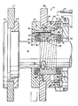
- the accompanying drawing is an elavational cross-sectional view showing the preferred embodiment mounted on a machine tool spindle and carrying a rotatable grinding tool.
- the machine for which the preferred embodiment is intended for use comprises a tool spindle 10 for supporting and driving a rotary tool, for example the grinding wheel I depicted, which is mounted on a spindle flange 12 and secured by a lock nut 13 threadably received on the spindle 10.
- the grinding wheel 11 serves as a reference point for axially positioning an adjustable tool mount 14 also carried by the spindle 10.
- the adjustable tool mounting device which is the preferred embodiment of this invention 14 likewise carries a grinding wheel 15 secured between a bock flange ring 16 and a front flange ring 17 which are fastened together in rigid assembly by a plurality of screws 18.
- the bock flange ring 16 has a flange portion 19 and a reduced tool pilot diameter 20 adjacent the flange portion 19.
- a precision central bore 21 through the back flange ring 16 is received on the machine tool spindle 10.
- a central counterbore 22 is provided in the tool pilot diameter 20, terminating at a counterbore seat 23.
- the front flange ring 17 has a flange portion 24 and an adjacent reduced tool pilot diameter 25 of the some size to that of the back flange ring 16.
- the outer end 26 of the flange portion 24 is provided with external threads.
- the front flange ring 17 has a central bore 27 of equivalent diameter to the central counterbore 22 of the back flange ring 16, and a counterbore 28 is provided in the flange portion 24, terminating at a counterbore seat 29 approximately midway through the front flange ring 24.
- An outer compression ring 30 is slidably received in the counterbore 28 of the front ring 17 and in normal assembly extends partway out of the flange ring 17.
- the outer compression ring 30 is cylindrical and has a central bore 31 slidably received on the machine tool spindle 10.
- a central counterbore 32 is machined in the compression ring 30 terminating at a counterbore seat 33.
- the counterbore 32 is of equal diameter to the central bore 27 of the front flange ring 17, and is disposed opening toward the back flange ring 16.
- a cylindrical inner compression ring 34 has a close-fitting bore 35 which is received on the machine tool spindle 10.
- the close-fitting outer diameter 36 of the inner compression ring 34 is slidably received in the back flange ring counterbore 22, the central bore 27 of the front flange ring 17, and the counterbore 32 of the outer compression ring 30.
- the inner compression ring 34 has on external key 37 which is received in a keyway 38 in the bock flange ring 16 to prevent relative rotation between the two.
- the outer compression ring 30 has an external key 39 which is received in a keyway 40 in the front flange ring 17 to prevent relative rotation between the two.
- An internal helical groove 41 is mochined within the bore 35 of the inner compression ring 34, and a pin member 42 seated in the machine tool spindle 10 projects radially into the internal groove 41.
- the cross-section of the pin 42 and groove 41 is relatively unimportant, so long as the two are cooperatingly formed to one another.
- a plurality of radially-extending holes 54 are provided around the circumference of the front flange rings 17, so that a spanner wrench (not shown) may be employed to rotate the adjustable tool mount 14. It can thus be seen that rotation of the front flange ring 17 will cause the back flange ring 16 and inner and outer compression rings 34, 30 to rotate in unison and axially move on the machine tool spindle 10, due to the torque transmission of the screws 18 and keys 37, 39.
- the rings 43 have been depicted with an exaggerated thickness, a variety of thicknesses may be employed, together with a variety of numbers of springs 43.
- the springs 43 each have a precision machined bore 44 and have a precision machined outer diameter 45, as well.
- conical spring rings 43 may be manufactured from a variety of materials, such rings are commercially available under several Trade Marks.
- the "Ringfeder” conical ring is a commercially available solid ring designed for clamping gears, sprockets, and the like in a fixed postion on a shaft.
- the “Ringspann” locking ring is another commercially available spring ring which is relieved at certain portions around its circumference so that it will have greater flex than a solid ring.
- a lock nut 46 is threadably received on the threaded end 26 of the front flange ring 17.
- the lock nut 46 has internal threads 47 terminating at an inner surface 48 which abouts the outer compression ring 30.
- a clearance hole 49 is mochined through the centre of the adjusting nut 46, and a plurality of rodially-extending holes 50 are machined in the circumference of the lock nut 46 so that a spanner wrench may be utilised in rotating the nut 46.
- lock nut 46 While the lock nut 46 may stay in its adjusted position due to frictional forces, a more secure assembly is attained by inserting a lock screw 51 through one of a plurality of closely spaced clearance holes 52 provided through the lock nut 46, any one of which may be aligned with a threaded hole 53 in the front flange ring 17.
- the invention has been shown in conjunction with a machine utilising a plurality of grinding wheels, but it may be appreciated that other tools, such as rotary milling cutters may be employed.
- seals within the cylindrical elements may also be preferred, in some instances, to provide seals within the cylindrical elements to create a water-tight assembly.
Landscapes
- Life Sciences & Earth Sciences (AREA)
- Engineering & Computer Science (AREA)
- Mechanical Engineering (AREA)
- Wood Science & Technology (AREA)
- Forests & Forestry (AREA)
- Constituent Portions Of Griding Lathes, Driving, Sensing And Control (AREA)
- Jigs For Machine Tools (AREA)
- Milling Processes (AREA)
- Polishing Bodies And Polishing Tools (AREA)
Applications Claiming Priority (2)
| Application Number | Priority Date | Filing Date | Title |
|---|---|---|---|
| US06/609,309 US4547997A (en) | 1984-05-11 | 1984-05-11 | Adjustable tool mount |
| US609309 | 1984-05-11 |
Publications (2)
| Publication Number | Publication Date |
|---|---|
| EP0164549A1 true EP0164549A1 (fr) | 1985-12-18 |
| EP0164549B1 EP0164549B1 (fr) | 1987-10-28 |
Family
ID=24440240
Family Applications (1)
| Application Number | Title | Priority Date | Filing Date |
|---|---|---|---|
| EP85105213A Expired EP0164549B1 (fr) | 1984-05-11 | 1985-04-29 | Dispositif pour porte-outil |
Country Status (4)
| Country | Link |
|---|---|
| US (1) | US4547997A (fr) |
| EP (1) | EP0164549B1 (fr) |
| JP (1) | JPS60242927A (fr) |
| DE (1) | DE3560815D1 (fr) |
Cited By (1)
| Publication number | Priority date | Publication date | Assignee | Title |
|---|---|---|---|---|
| DE3724698A1 (de) * | 1987-07-25 | 1989-02-02 | Schaudt Maschinenbau Gmbh | Schleifkopf |
Families Citing this family (11)
| Publication number | Priority date | Publication date | Assignee | Title |
|---|---|---|---|---|
| SE446319B (sv) * | 1982-01-07 | 1986-09-01 | Lennart Johannesson | Anordning vid delade fresar |
| JPS61146692A (ja) * | 1984-12-18 | 1986-07-04 | 本田技研工業株式会社 | 鞍乗り型車両の前輪懸架装置 |
| US5113735A (en) * | 1991-04-23 | 1992-05-19 | Alcan International Limited | Slitting apparatus |
| JP2596245Y2 (ja) * | 1992-06-19 | 1999-06-07 | 株式会社日平トヤマ | 可動型砥石軸 |
| FR2698032B1 (fr) * | 1992-11-16 | 1995-10-06 | Metabowerke Gmbh | Dispositif de serrage rapide destine au serrage axial d'un outil en forme de disque. |
| US7013987B2 (en) * | 2000-09-08 | 2006-03-21 | Black & Decker | Clutch assembly and clamp mechanism for rotary tool disc |
| JP4576357B2 (ja) * | 2006-06-02 | 2010-11-04 | 有限会社信立 | ワークのかさ上げ治具 |
| DE102007001864A1 (de) * | 2007-01-12 | 2008-07-17 | Kennametal Inc. | Fräsvorrichtung |
| EP2676767B1 (fr) | 2008-12-19 | 2015-08-19 | Etp Transmission Ab | Système de support d'outil et procédé de réglage d'une position axiale d'un outil ou d'une partie d'outil |
| CN102825322A (zh) * | 2012-09-12 | 2012-12-19 | 孙效 | 多面组合铣削机构 |
| PT2974840T (pt) * | 2014-07-17 | 2017-08-08 | Schiavon S R L | Utensílio rotativo de espessura regulável |
Citations (2)
| Publication number | Priority date | Publication date | Assignee | Title |
|---|---|---|---|---|
| FR2058221A1 (fr) * | 1969-08-12 | 1971-05-28 | Toyoda Machine Works Ltd | |
| US3912411A (en) * | 1971-09-22 | 1975-10-14 | Robert H Moffat | Thread latching mechanism |
Family Cites Families (6)
| Publication number | Priority date | Publication date | Assignee | Title |
|---|---|---|---|---|
| US813167A (en) * | 1905-07-28 | 1906-02-20 | Leverett H Olmsted | Grinding apparatus. |
| US1706206A (en) * | 1928-05-09 | 1929-03-19 | Vermont Marble Co | Arbor |
| US1974553A (en) * | 1934-01-13 | 1934-09-25 | Peyton Du Pont Inc | Mandrel |
| US3172326A (en) * | 1962-08-29 | 1965-03-09 | United States Steel Corp | Knife-mounting means for slitting shear |
| JPS4845278U (fr) * | 1971-09-29 | 1973-06-13 | ||
| FR2430287A1 (fr) * | 1978-07-05 | 1980-02-01 | Tobler Sa | Mandrin expansible |
-
1984
- 1984-05-11 US US06/609,309 patent/US4547997A/en not_active Expired - Fee Related
-
1985
- 1985-04-29 DE DE8585105213T patent/DE3560815D1/de not_active Expired
- 1985-04-29 EP EP85105213A patent/EP0164549B1/fr not_active Expired
- 1985-05-10 JP JP60099420A patent/JPS60242927A/ja active Granted
Patent Citations (2)
| Publication number | Priority date | Publication date | Assignee | Title |
|---|---|---|---|---|
| FR2058221A1 (fr) * | 1969-08-12 | 1971-05-28 | Toyoda Machine Works Ltd | |
| US3912411A (en) * | 1971-09-22 | 1975-10-14 | Robert H Moffat | Thread latching mechanism |
Cited By (1)
| Publication number | Priority date | Publication date | Assignee | Title |
|---|---|---|---|---|
| DE3724698A1 (de) * | 1987-07-25 | 1989-02-02 | Schaudt Maschinenbau Gmbh | Schleifkopf |
Also Published As
| Publication number | Publication date |
|---|---|
| DE3560815D1 (en) | 1987-12-03 |
| JPH0232115B2 (fr) | 1990-07-18 |
| EP0164549B1 (fr) | 1987-10-28 |
| JPS60242927A (ja) | 1985-12-02 |
| US4547997A (en) | 1985-10-22 |
Similar Documents
| Publication | Publication Date | Title |
|---|---|---|
| US5027684A (en) | Collar for mounting a split saw blade on an arbor | |
| EP0682585B1 (fr) | Appareil et procede d'equilibrage d'outils rotatifs | |
| EP0164549B1 (fr) | Dispositif pour porte-outil | |
| DE69526451T2 (de) | Rotierendes ringförmiges schmeidewerkzeug mit frontladung | |
| US4993888A (en) | Cutting tool arrangement | |
| US5431416A (en) | Collet attachment/closer | |
| EP3592489A1 (fr) | Butée destinée à un outil de perçage, de fraisage ou de lamage | |
| EP0759831B1 (fr) | Dispositif de transmission de forces d'entrainement | |
| US4893967A (en) | Cutting tool arrangement | |
| US5649460A (en) | Quick-change spindle liner assembly | |
| US4828436A (en) | Cutting tool cartridge arrangement | |
| CN210755238U (zh) | 刀具组件 | |
| CA1254404A (fr) | Dispositif de reglage d'excentricite | |
| US6810733B2 (en) | Balancing system for compensating for unbalance of a rotating machine part | |
| SE460712B (sv) | Revolverhuvud foer en svarv och haertill avpassad verktygshaallare | |
| US5360283A (en) | Preload-clampnut device | |
| US4544309A (en) | Adjustable cutting or boring tool | |
| WO2009121461A1 (fr) | Outil de brochage rotatif par tournage ou de fraisage de profil | |
| EP0799663B1 (fr) | Tourelle porte-outil spécialement pour tours | |
| US5083484A (en) | Pipe end preparation tool having improved torque reacting and clamping capabilities | |
| US3654826A (en) | Adjustable tool block assembly | |
| US4164381A (en) | Facing and grooving tool | |
| EP0494864B1 (fr) | Outil de preparation d'extremites de tuyaux a capacite amelioree de serrage et d'application de couple antagoniste | |
| US5481945A (en) | Lock plate adjustment for geneva drive mechanism | |
| DE19629610A1 (de) | Einfaches Feinverstellsystem für einschneidige Bohrstangen |
Legal Events
| Date | Code | Title | Description |
|---|---|---|---|
| PUAI | Public reference made under article 153(3) epc to a published international application that has entered the european phase |
Free format text: ORIGINAL CODE: 0009012 |
|
| 17P | Request for examination filed |
Effective date: 19850524 |
|
| AK | Designated contracting states |
Designated state(s): DE FR GB NL |
|
| 17Q | First examination report despatched |
Effective date: 19870116 |
|
| GRAA | (expected) grant |
Free format text: ORIGINAL CODE: 0009210 |
|
| AK | Designated contracting states |
Kind code of ref document: B1 Designated state(s): DE FR GB NL |
|
| REF | Corresponds to: |
Ref document number: 3560815 Country of ref document: DE Date of ref document: 19871203 |
|
| ET | Fr: translation filed | ||
| PLBE | No opposition filed within time limit |
Free format text: ORIGINAL CODE: 0009261 |
|
| STAA | Information on the status of an ep patent application or granted ep patent |
Free format text: STATUS: NO OPPOSITION FILED WITHIN TIME LIMIT |
|
| 26N | No opposition filed | ||
| PGFP | Annual fee paid to national office [announced via postgrant information from national office to epo] |
Ref country code: NL Payment date: 19930430 Year of fee payment: 9 |
|
| PG25 | Lapsed in a contracting state [announced via postgrant information from national office to epo] |
Ref country code: NL Effective date: 19941101 |
|
| NLV4 | Nl: lapsed or anulled due to non-payment of the annual fee | ||
| PGFP | Annual fee paid to national office [announced via postgrant information from national office to epo] |
Ref country code: FR Payment date: 19950411 Year of fee payment: 11 |
|
| PGFP | Annual fee paid to national office [announced via postgrant information from national office to epo] |
Ref country code: GB Payment date: 19950418 Year of fee payment: 11 |
|
| PGFP | Annual fee paid to national office [announced via postgrant information from national office to epo] |
Ref country code: DE Payment date: 19950421 Year of fee payment: 11 |
|
| PG25 | Lapsed in a contracting state [announced via postgrant information from national office to epo] |
Ref country code: GB Effective date: 19960429 |
|
| GBPC | Gb: european patent ceased through non-payment of renewal fee |
Effective date: 19960429 |
|
| PG25 | Lapsed in a contracting state [announced via postgrant information from national office to epo] |
Ref country code: FR Effective date: 19961227 |
|
| PG25 | Lapsed in a contracting state [announced via postgrant information from national office to epo] |
Ref country code: DE Effective date: 19970101 |
|
| REG | Reference to a national code |
Ref country code: FR Ref legal event code: ST |