EP0164152A2 - Elektrooptische Anzeigevorrichtung - Google Patents
Elektrooptische Anzeigevorrichtung Download PDFInfo
- Publication number
- EP0164152A2 EP0164152A2 EP85200689A EP85200689A EP0164152A2 EP 0164152 A2 EP0164152 A2 EP 0164152A2 EP 85200689 A EP85200689 A EP 85200689A EP 85200689 A EP85200689 A EP 85200689A EP 0164152 A2 EP0164152 A2 EP 0164152A2
- Authority
- EP
- European Patent Office
- Prior art keywords
- group
- display elements
- character
- matrix
- elements
- Prior art date
- Legal status (The legal status is an assumption and is not a legal conclusion. Google has not performed a legal analysis and makes no representation as to the accuracy of the status listed.)
- Withdrawn
Links
Images

Classifications
-
- G—PHYSICS
- G09—EDUCATION; CRYPTOGRAPHY; DISPLAY; ADVERTISING; SEALS
- G09F—DISPLAYING; ADVERTISING; SIGNS; LABELS OR NAME-PLATES; SEALS
- G09F9/00—Indicating arrangements for variable information in which the information is built-up on a support by selection or combination of individual elements
- G09F9/30—Indicating arrangements for variable information in which the information is built-up on a support by selection or combination of individual elements in which the desired character or characters are formed by combining individual elements
- G09F9/302—Indicating arrangements for variable information in which the information is built-up on a support by selection or combination of individual elements in which the desired character or characters are formed by combining individual elements characterised by the form or geometrical disposition of the individual elements
-
- G—PHYSICS
- G02—OPTICS
- G02F—OPTICAL DEVICES OR ARRANGEMENTS FOR THE CONTROL OF LIGHT BY MODIFICATION OF THE OPTICAL PROPERTIES OF THE MEDIA OF THE ELEMENTS INVOLVED THEREIN; NON-LINEAR OPTICS; FREQUENCY-CHANGING OF LIGHT; OPTICAL LOGIC ELEMENTS; OPTICAL ANALOGUE/DIGITAL CONVERTERS
- G02F1/00—Devices or arrangements for the control of the intensity, colour, phase, polarisation or direction of light arriving from an independent light source, e.g. switching, gating or modulating; Non-linear optics
- G02F1/01—Devices or arrangements for the control of the intensity, colour, phase, polarisation or direction of light arriving from an independent light source, e.g. switching, gating or modulating; Non-linear optics for the control of the intensity, phase, polarisation or colour
- G02F1/13—Devices or arrangements for the control of the intensity, colour, phase, polarisation or direction of light arriving from an independent light source, e.g. switching, gating or modulating; Non-linear optics for the control of the intensity, phase, polarisation or colour based on liquid crystals, e.g. single liquid crystal display cells
- G02F1/133—Constructional arrangements; Operation of liquid crystal cells; Circuit arrangements
- G02F1/1333—Constructional arrangements; Manufacturing methods
- G02F1/1343—Electrodes
- G02F1/134309—Electrodes characterised by their geometrical arrangement
- G02F1/134327—Segmented, e.g. alpha numeric display
Definitions
- the present invention relates to an alphanumerical electro-optical display device having at least one character which is composed of a plurality of individual dot-shaped display elements, in which the display elements can be controlled electrically and be optically activated by the electric control and are arranged in the form of a matrix in lines and columns.
- a display device is known, for example, from "Elektroniker" No. 2, 1980, p.EL1 - EL5.
- Alpha-numerical display devices of the known type customarily comprise several characters which are arranged beside each other to form a line and enable the simultaneous display of, for example, 4, 16 or 32 characters.
- Each individual character consists of a plurality of dot-shaped display elements which are arranged in the form of a matrix ( 5 x 7; 7 x 11 or differently).
- the individual display elements may operate according to different principles and may, for example, be in the form of a LED (Light Emitting Diode), LCD (Liquid Crystal Display), fluorescent or plasma display.
- each display element requires, for a character in the form of a (5 x 7) matrix, 35 control lines, hence 560 control lines in a 16 character line which are associated with the 560 display elements of said line.
- Such an individual control of the display elements hence leads to high wiring costs, which simultaneously is associated with high costs of control electronics.
- control line displays with a multiplexing ratio of only 1 : 2 or at least 1 : 4.
- the 560 control lines of a 16 character line are reduced by ( 5 x 7) dot characters to 280 control lines. Inspite of this reduction disproportionately high control costs remain which decesively determine the cost of manufacture of the display device and make the use of large series doubtful.
- a display device of the kind mentioned in the opening paragraph is characterized in that selected display elements are connected together pairwise so that the display elements of the same pair are always optically activated simulatneously.
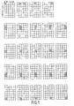
- the character has the form of a matrix 8 with 35 individual display elements 9 which are shown diagrammatically in Fig. 1 as juxtaposed squares.
- the display elements optically activated in an elementary display condition are shown as full black squares.
- the display elements of line 4 of line 7 can each be optically activated, that on the other hand each time the second and third as well as the fifth and sixth display element of each column A ... E are activated optically only pairwise.
- the second and fourth display element are combined to form a pair while the remaining display elements of said line can be optically activated individually.
- the display elements are preferably constructed in LCD technology.
- Eaah display element comprises a counter electrode, a main electrode and a liquid crystal layer present between the two electrodes.
- the pairwise connection of selected display elements is produced by suitable electrically conductive connections each time between the counter electrodes and the main electrodes, respectively, of various display elements. It is particularly advantageous to provide a liquid crystal layer which is common to all the display elements for the matrix of a character or in a line consisting of several characters for the whole line, so that the individual display elements are formed only by the special configuration of the counter electrodes and the oppositely located main electrodes in a common liquid crystal cell.
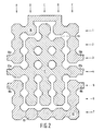
- a first configuration of the counter electrode for a character according to the preferred embodiment is shown in Fig. 2.
- an individual counter electrode 13 is provided in the form of an irregular octagon.
- the 35 counter electrodes 13 are connected in three groups.
- the first group comprises the counter electrodes of the display elements 1A, 1B, 1D, 1E, 2A, 2E, 3A and 3E and forms a coherent upper counter electrode 10.
- the second group comprises the counter electrodes of the display elements 5A, 5E, 6A, 6E, 7A, 7B, 7C, 7D and 7E and forms a coherent lower counter electrode 12.
- the third group comprises all the remaining counter electrodes and forms a coherent central counter electrode 11.
- left and right electrode connections 16a, 16b, 17a, 17b and 18a, 18b may be provided on the left and right hand sides of the upper counter electrode 10, of the central counter electrode 11, and of the lower counter electrode 12, via which connections corresponding counter electrodes of adjacent characters can be connected together so as to be electrically conductive.
- the whole line has a common upper, central and lower counter electrode.
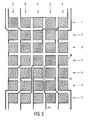
- Fig. 3 The main electrode configuration associated with the counter electrode configuration of Fig. 2 is shown in Fig. 3. Whereas in Fig. 2 the electrode surfaces are shaded, the corresponding surfaces and connection lines are now shown as black squares and lines for clarity.
- the square individual main electrodes 20 of the display elements in this case also are combined to form groups, each group comprising at least two and at most four display elements.
- the character totally has twelve groups of main electrodes 20 which comprise the following display elements:
- connection lines 15 are provided so that the intermediate spaces 19 between the counter electrofes of Fig'. 2 are oppositely located. In this manner undesired crossings between counter electrodes and main electrodes are avoided which might lead to the formation of additional stray display elements.
- Each of the twelve main electrode groups can be controlled from without by an individual connection line 14 so that per character twelve control lines for the main electrodes are present.
- the combination of the main electrodes 20 to form groups has been chosen to be so that in none of the twelve groups two display elements are present one of which has its counter electrode 13 within the upper counter electrode 10 and the other of which has its counter electrode 13 within the lower counter electrode 12.
- the upper counter electrode 10 and the lower counter electrode 12 may hence be conductively connected and be controlled in common without losing one of the elementary control conditions of Fig. 1.
- the control of the upper, central and lower counter electrodes 11, 12, and of the twelve groups of main electrodes occurs in duplex operation i.e, in a time multiplexing method with a multiplexing ratio of 1 : 2.
- the central counter electrode 11 and on the other hand the upper and lower counter electrodes 10 and 12 are alternately controlled. Synchronously with said control of the counter electrodes each time only those main electrode groups are selected via the connection line 14 which in cooperation with the just controlled counter electrodes optically activate the desired display elements.
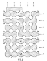
- FIG. 4 A second configuration of the counter electrode for a character according to the preferred embodiment is shown in Fig. 4. This second counter electrode configuration is designed for a multiplexing operation of the display device with a multplexing ratio 1 : 4.
- an individual counter electrode 13 in the form of an irregular octagon is provided for each of the 35 display elements of the (5 x 7) dot character.
- the 35 counter electrodes 13, however, are now combined in four instead of three groups, the counter electrodes of the display elements 1A, ... 1E, 2D, 2E, 3D and 3E forming a coherent upper counter electrode 25, the counter electrodes of the display elements 2A, 2B, 2C, 3A, 3B, 3C, 4C, 4D and 4E forming a coherent first central counter electrode 26, the counter electrodes of the display elements 4A, 4B, 5B, ... 5E, 6B, ... 6E forming a coherent second central counter electrode 27, and the counter electrodes of the remaining display elements 5A, 6A, 7A, ... 7E forming a coherent lower counter electrode 28 which can be recognized by different shading in Fig. 4.
- left and right electrode connections 29a, 29b, 30a, 30b, 31a, 31b, 32a and 32b may be provided in this case also on the left and right hand sides of the upper counter electrode 25, of the two central counter electrodes 26 and 27, and of the lower counter electrode 28, via which connections corresponding counter electrodes of adjacent characters can be interconnected so as to be electrically conductive.
- the main electrode configuration associated with the counter electrode configuration of Fig. 4 is shown in Fig. 5.
- the electrode surfaces which are transparent and the connection lines are shown as full black surfaces.
- the main electrodes 20 of Fig. 5 are combined in six groups which comprise the following display elements:
- connection lines 15 are again interconnected so as to be electrically conductive.
- connection lines 33-44 are shown in broken lines in Fig. 5, two connection lines being associated with each main electrode group.
- the upper six 33-38 or the lower six 39-44 can be realized when all the main electrode connections are to be made on one side of the character.
- connection lines 33, 34, 38, 41, 42 and 43 may be used in combination. In this manner all possible contacting cases for the display device can be realized.
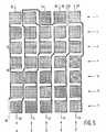
- the complete control circuit of a 16 character LCD line for duplex operation constructed with (5 x 7) characters shown in Fig. 2 is shown in Fig. 7.
- Fig. 7 For clarity only the first, second and last character, C1, C2 and C16 of the 26 characters of the line are shown.
- a plurality of control circuits are provided of which the first, S1, and the last, S6, are shown.
- control circuits may be used, for example the integrated circuits of the type PCE 2111 of "Philips" intended for the duplex operation of LCD displays.
- Said ICs each have 32 driver outputs for controlling 32 different display elements as well as two outputs for controlling two different counter electrodes in the duplex method.
- the upper and lower counter electrodes 10 and 12 of all the characters C1, C2, C16 are connected in common via a second counter electrode line RE2 to the second counter electrode output of the first control circuit S1.
- the central counter electrodes 11 of all the characters C1, C2, C16 are connected via a first counter electrode line RE1 to the first control circuit S1.
- the corresponding counter electrode outputs of all the control circuits S1, S6 are interconnected to match the controls of all the characters of the line with each other.
- each control circuit S1 S6, 32 driver lines 21, 22 lead to the various associated characters. Since in twelve main electrode groups per character only each time twelve of the 32 driver lines 21, 22 per character are required, the totality of the driver lines of a control circuit is distributed over various characters.
- driver lines are required for the control of a 16 character line with (5 x 7) characters without time multiplexing method.
- the number of driver lines is halved to 280 so that for the control in this case 9 integrated circuits of the type PCE 2111 with totally 280 driver lines must be used.
- control of the control circuits S1, S6 occurs in known manner via corresponding clock burst inputs 23 data inputs 24 and data-line-enable-inputs EN1, EN6, whose operation can be derived from the data of the various control circuits.
Landscapes
- Physics & Mathematics (AREA)
- General Physics & Mathematics (AREA)
- Nonlinear Science (AREA)
- Chemical & Material Sciences (AREA)
- Crystallography & Structural Chemistry (AREA)
- Mathematical Physics (AREA)
- Geometry (AREA)
- Optics & Photonics (AREA)
- Engineering & Computer Science (AREA)
- Theoretical Computer Science (AREA)
- Devices For Indicating Variable Information By Combining Individual Elements (AREA)
- Liquid Crystal Display Device Control (AREA)
- Liquid Crystal (AREA)
- Control Of Indicators Other Than Cathode Ray Tubes (AREA)
- Control Of El Displays (AREA)
Applications Claiming Priority (2)
| Application Number | Priority Date | Filing Date | Title |
|---|---|---|---|
| CH224484 | 1984-05-08 | ||
| CH2244/84 | 1984-05-08 |
Publications (2)
| Publication Number | Publication Date |
|---|---|
| EP0164152A2 true EP0164152A2 (de) | 1985-12-11 |
| EP0164152A3 EP0164152A3 (de) | 1986-10-08 |
Family
ID=4229224
Family Applications (1)
| Application Number | Title | Priority Date | Filing Date |
|---|---|---|---|
| EP85200689A Withdrawn EP0164152A3 (de) | 1984-05-08 | 1985-05-02 | Elektrooptische Anzeigevorrichtung |
Country Status (2)
| Country | Link |
|---|---|
| EP (1) | EP0164152A3 (de) |
| JP (1) | JPS6111785A (de) |
Cited By (4)
| Publication number | Priority date | Publication date | Assignee | Title |
|---|---|---|---|---|
| EP0159068A3 (de) * | 1984-03-26 | 1988-09-28 | Philips Electronics Uk Limited | Alphanumerische Anzeigeeinheit und visuelle Anzeigeeinrichtung mit solchen Einheiten |
| DE3816550A1 (de) * | 1988-05-11 | 1989-11-23 | Krone Ag | Elektrooptische flachanzeigetafel fuer alphanumerische zeichen |
| EP0421517A1 (de) * | 1989-09-28 | 1991-04-10 | Koninklijke Philips Electronics N.V. | Alphanumerische Wiedergabeanordnung |
| US5585948A (en) * | 1995-02-22 | 1996-12-17 | Three-Five Systems, Inc. | Dot matrix liquid crystal display with low multiplex ratio with each column electrode connected to only one other |
Family Cites Families (3)
| Publication number | Priority date | Publication date | Assignee | Title |
|---|---|---|---|---|
| DE2757555A1 (de) * | 1977-11-30 | 1979-05-31 | Bbc Brown Boveri & Cie | Elektrooptische anzeigevorrichtung |
| GB2055234A (en) * | 1979-06-25 | 1981-02-25 | Sci Sys W Ltd | Improvements in electronic same apparatus |
| GB2114354B (en) * | 1982-02-01 | 1985-11-20 | Secr Defence | Character display |
-
1985
- 1985-05-02 EP EP85200689A patent/EP0164152A3/de not_active Withdrawn
- 1985-05-08 JP JP9613085A patent/JPS6111785A/ja active Pending
Cited By (4)
| Publication number | Priority date | Publication date | Assignee | Title |
|---|---|---|---|---|
| EP0159068A3 (de) * | 1984-03-26 | 1988-09-28 | Philips Electronics Uk Limited | Alphanumerische Anzeigeeinheit und visuelle Anzeigeeinrichtung mit solchen Einheiten |
| DE3816550A1 (de) * | 1988-05-11 | 1989-11-23 | Krone Ag | Elektrooptische flachanzeigetafel fuer alphanumerische zeichen |
| EP0421517A1 (de) * | 1989-09-28 | 1991-04-10 | Koninklijke Philips Electronics N.V. | Alphanumerische Wiedergabeanordnung |
| US5585948A (en) * | 1995-02-22 | 1996-12-17 | Three-Five Systems, Inc. | Dot matrix liquid crystal display with low multiplex ratio with each column electrode connected to only one other |
Also Published As
| Publication number | Publication date |
|---|---|
| JPS6111785A (ja) | 1986-01-20 |
| EP0164152A3 (de) | 1986-10-08 |
Similar Documents
| Publication | Publication Date | Title |
|---|---|---|
| US4449123A (en) | Dot matrix type multi-layer liquid crystal display device | |
| US20220344415A1 (en) | Display panel and display apparatus | |
| US5805136A (en) | Intermingling subpixels in discrete level displays | |
| US4365244A (en) | Arrangement for displaying images using light emitting diodes | |
| US4308534A (en) | Multiplexing liquid crystal display device having different display formats | |
| KR20040020317A (ko) | 액정 표시 장치 및 그 구동 방법 | |
| JPH022585A (ja) | 千鳥形三原色を有する画素配列体 | |
| CA1082378A (en) | Abuttable light-emitting device modules for graphic display assemblies | |
| EP0146285A2 (de) | Flache elektrooptische Anzeigetafel | |
| KR100660446B1 (ko) | 디스플레이 드라이버를 위한 버스 배열 | |
| JP2005316467A (ja) | ディスプレイの画素アレイ及びディスプレイ | |
| EP0164152A2 (de) | Elektrooptische Anzeigevorrichtung | |
| KR19990014878A (ko) | 플라즈마-어드레스 디스플레이 | |
| US4513282A (en) | Liquid crystal matrix display device | |
| KR20070046876A (ko) | 능동 매트릭스 디바이스 | |
| EP0119167A2 (de) | Verfahren und Einrichtung, insbesondere tauglich für Motorfahrzeuge zur selektiven Abbildung von identischen Informationen in unterschiedlichen Sprachen | |
| GB2052825A (en) | Alpha-numeric display device for large and small characters | |
| GB1593004A (en) | Gaseous discharge display devices | |
| WO2007043003A1 (en) | In-plane switching display devices | |
| JPS63138388A (ja) | 表示装置 | |
| CN115933236B (zh) | 显示面板和显示装置 | |
| KR100244131B1 (ko) | 다전극소자의 접속구조 | |
| JP2531756B2 (ja) | 平面表示板用陽極基板の製造方法 | |
| US4266224A (en) | High performance information display panel | |
| US4081717A (en) | Zigzag shifting self-transfer type display device |
Legal Events
| Date | Code | Title | Description |
|---|---|---|---|
| PUAI | Public reference made under article 153(3) epc to a published international application that has entered the european phase |
Free format text: ORIGINAL CODE: 0009012 |
|
| AK | Designated contracting states |
Designated state(s): CH DE FR GB LI |
|
| PUAL | Search report despatched |
Free format text: ORIGINAL CODE: 0009013 |
|
| AK | Designated contracting states |
Kind code of ref document: A3 Designated state(s): CH DE FR GB LI |
|
| STAA | Information on the status of an ep patent application or granted ep patent |
Free format text: STATUS: THE APPLICATION IS DEEMED TO BE WITHDRAWN |
|
| 18D | Application deemed to be withdrawn |
Effective date: 19870409 |
|
| RIN1 | Information on inventor provided before grant (corrected) |
Inventor name: NEUMANN, LUDWIG |