EP0163771A2 - Senkbrems-Sperrventil - Google Patents
Senkbrems-Sperrventil Download PDFInfo
- Publication number
- EP0163771A2 EP0163771A2 EP84115881A EP84115881A EP0163771A2 EP 0163771 A2 EP0163771 A2 EP 0163771A2 EP 84115881 A EP84115881 A EP 84115881A EP 84115881 A EP84115881 A EP 84115881A EP 0163771 A2 EP0163771 A2 EP 0163771A2
- Authority
- EP
- European Patent Office
- Prior art keywords
- spring
- control piston
- control
- valve
- check valve
- Prior art date
- Legal status (The legal status is an assumption and is not a legal conclusion. Google has not performed a legal analysis and makes no representation as to the accuracy of the status listed.)
- Withdrawn
Links
Images

Classifications
-
- F—MECHANICAL ENGINEERING; LIGHTING; HEATING; WEAPONS; BLASTING
- F15—FLUID-PRESSURE ACTUATORS; HYDRAULICS OR PNEUMATICS IN GENERAL
- F15B—SYSTEMS ACTING BY MEANS OF FLUIDS IN GENERAL; FLUID-PRESSURE ACTUATORS, e.g. SERVOMOTORS; DETAILS OF FLUID-PRESSURE SYSTEMS, NOT OTHERWISE PROVIDED FOR
- F15B11/00—Servomotor systems without provision for follow-up action; Circuits therefor
- F15B11/003—Systems with load-holding valves
-
- F—MECHANICAL ENGINEERING; LIGHTING; HEATING; WEAPONS; BLASTING
- F15—FLUID-PRESSURE ACTUATORS; HYDRAULICS OR PNEUMATICS IN GENERAL
- F15B—SYSTEMS ACTING BY MEANS OF FLUIDS IN GENERAL; FLUID-PRESSURE ACTUATORS, e.g. SERVOMOTORS; DETAILS OF FLUID-PRESSURE SYSTEMS, NOT OTHERWISE PROVIDED FOR
- F15B13/00—Details of servomotor systems ; Valves for servomotor systems
- F15B13/01—Locking-valves or other detent i.e. load-holding devices
- F15B13/015—Locking-valves or other detent i.e. load-holding devices using an enclosed pilot flow valve
-
- F—MECHANICAL ENGINEERING; LIGHTING; HEATING; WEAPONS; BLASTING
- F16—ENGINEERING ELEMENTS AND UNITS; GENERAL MEASURES FOR PRODUCING AND MAINTAINING EFFECTIVE FUNCTIONING OF MACHINES OR INSTALLATIONS; THERMAL INSULATION IN GENERAL
- F16K—VALVES; TAPS; COCKS; ACTUATING-FLOATS; DEVICES FOR VENTING OR AERATING
- F16K15/00—Check valves
- F16K15/18—Check valves with actuating mechanism; Combined check valves and actuated valves
-
- F—MECHANICAL ENGINEERING; LIGHTING; HEATING; WEAPONS; BLASTING
- F15—FLUID-PRESSURE ACTUATORS; HYDRAULICS OR PNEUMATICS IN GENERAL
- F15B—SYSTEMS ACTING BY MEANS OF FLUIDS IN GENERAL; FLUID-PRESSURE ACTUATORS, e.g. SERVOMOTORS; DETAILS OF FLUID-PRESSURE SYSTEMS, NOT OTHERWISE PROVIDED FOR
- F15B2211/00—Circuits for servomotor systems
- F15B2211/50—Pressure control
- F15B2211/505—Pressure control characterised by the type of pressure control means
- F15B2211/50509—Pressure control characterised by the type of pressure control means the pressure control means controlling a pressure upstream of the pressure control means
- F15B2211/50545—Pressure control characterised by the type of pressure control means the pressure control means controlling a pressure upstream of the pressure control means using braking valves to maintain a back pressure
Definitions
- the invention relates to a lowering brake check valve for load-independent hydraulic control with a housing, operating connections provided in the housing, which in one direction against the spring force of a locking arrangement arranged inside the housing and in the opposite direction by a control connection to the locking arrangement in connection standing against the breech arrangement control piston can be connected, with an annular space connected to the service port assigned to the consumer side, which can be closed and opened by a breech assembly belonging to the breech assembly to the service side associated service port, the piston assembly having a control piston which contains a longitudinal through-bore, in which a spring-loaded valve closes the hydraulic preload opening to the supply connection, which can be opened with the aid of the control piston, and with one on the preload End opening remote end arranged in the piston assembly spring chamber.
- Such valves are used to move and hold cranes, for example.
- valve If the valve is open in controlled operation, if there is a pipe break on the consumer side, it will behave properly when the load is lowered. If the auxiliary piston spring breaks and the control pressure drops, the valve cannot close. If the trailing piston spring breaks, the auxiliary piston spring has to move the pilot piston against the applied oil pressure in this operating case.
- the present invention has for its object to provide a counterbalance lock y entil that allows safe operation in normal operation and in the event of malfunctions in the supply lines and spring breaks inside the valve by either controlling the load further or keeping it in its state can.
- the task for an over-center lock valve of the above-characterized A rt is inventively achieved in that the annular space through a return hole is disposed in a throttle device, is connected non-closable with the spring chamber.
- the throttle device is advantageously designed as a nozzle.
- the pre-relief valve spring is supported on the end of the control piston facing away from the pre-relief opening and a control piston spring is arranged between the end of the control piston facing away from the annular space and the opposite end of the spring space.
- the control piston spring acts as a counterforce for the pressure on the control piston.
- the control piston spring breaks during uncontrolled operation due to the closed pre-relief valve, the control piston can close due to the pressure build-up in the spring chamber made possible by the return connection.
- the pre-relief valve spring will close the pre-relief valve as the control pressure at the control connection decreases and stop relieving the spring chamber.
- a pressure also builds up in the spring chamber via the return connection, which pressure is able to close the opening by the control piston. Due to the design, even if the pre-relief valve spring breaks, the pre-relief valve can be closed. Without a broken spring, the closing movement takes place mechanically and hydraulically.
- a check valve is expediently also integrated in the closure arrangement, which allows the opening between the consumer and supply in uncontrolled operation to be released quickly and acts as a bypass valve for the control valve.
- This is advantageously achieved in that a non-return sleeve with connecting openings to the annular space is arranged concentrically around the control piston.
- the check sleeve expediently has a driver device for the control piston and the control piston has a driver device for the check sleeve.
- the check sleeve must have connection openings to the annulus to function, so that in controlled operation, in which the check sleeve remains in the idle state, the connection between consumer and supplier can be established via the opening between the control piston and the check sleeve.
- control piston including the pre-relief valve, is carried along by the inner stop of the driver device, so that a larger opening cross section is released.
- the closing process can be carried out solely by the control piston spring, since the check sleeve is positively controlled by the control piston in the opposite direction.
- the control piston In the region of the end facing the annular space, the control piston has a seat surface which forms the driver device. This seat can serve as a driver and as a stop, the design being able to be varied within the framework of the considerations familiar to the person skilled in the art.
- a check spring is expediently arranged between the end of the check sleeve facing away from the annular space and the opposite end of the spring area. This spring supports the closing movement of the check sleeve, so that the closing of the flow opening is carried out by means of a check spring and a control piston spring. If the non-return spring breaks, the closure can take place through the above-mentioned positive control of the non-return sleeve by the control piston. If the control piston spring breaks, it is closed by the pressure in the spring chamber.
- the non-return spring can of course also be supported on a shoulder or the like arranged in the spring chamber.
- the non-return sleeve preferably has a pressure surface facing the supply connection and a sealing surface sealing against the inner wall of the housing towards the annular space.
- the control piston is advantageously provided with control slots at its end sealing the opening between the control piston and the check sleeve.
- the check sleeve is designed in such a way that a consumer back pressure is unable to unintentionally check the check valve to open because there is no difference surface.
- the configuration in the area of the flow opening from the supply connection to the consumer connection serves for the uncontrolled operation of the quick opening when a pressure predetermined by the spring forces is exceeded and the safe leak-free sealing.
- the design serves for the release and the closing of the non-return sleeve interior through control slots, corresponding to the actuation pressure and the spring counterforce.
- the chamfer of the seat surfaces of the individual valves i.e. the sealing surfaces between the housing and non-return sleeve, non-return sleeve and control piston and control piston and pre-relief valve ball is advantageously approximately 45 °.
- control valve and the check valve are integrated in one housing bore as a cartridge valve. In practice, this enables easy handling and requires less space.
- the present invention provides a counterbalance check valve with a bypass check valve as a cartridge valve in a housing, which has a control valve, consisting of the control piston and the associated parts, and with a corresponding functional design in the area the opening and the seat surfaces, which has a check valve that bypasses the control valve, also with the structure required for the function in the area of the flow opening and the seat surfaces, which closes securely when necessary, even if individual springs break, and prevents the load from falling. This avoids an undefined state of the valve in the event of internal faults and prevents leakage.
- Another advantage lies in the overall structure, which enables the valve to be adjusted to certain desired operating states and properties. This can be done by selecting and tuning the nozzle and springs.
- the function of the valve can also be influenced by changing the ball diameter of the pre-relief ball closing the pre-relief valve.
- the arrangement of all the springs on one side of the flow opening and the load transfer of only individual springs in certain operating states make it possible to dimension the springs appropriately.
- the control piston spring has to maintain the actuation pressure in the controlled operation, while the pre-relief valve spring only counteracts the pre-relief pressure. In uncontrolled operation, the pressure force is distributed to the control piston spring and the return spring.
- the lowering brake check valve shown in FIG. 1 is designed as a cartridge valve and consists of a housing which has a valve body 29 and a valve cover 28.
- a connection A and a connection B which is indicated by a dash-dotted circular line.
- the control connection X is arranged on the front side.
- the connection A is connected externally to a supply device and the connection B to the load or the consumer.
- the connection A has a prechamber 23 and a main chamber 24 connected to this prechamber.
- an internal shuttle valve for special functions is connected to the prechamber 23.
- the connection B is connected to an annular space 1 arranged inside the valve.
- the opening between the annular space 1 and the main chamber 24 is closed by a closure arrangement which has a piston arrangement with springs.
- a control piston 7 is provided on the X connection, which serves to control the valve, one end of which projects into the main chamber 24 and has a pin 8 which is movably inserted into the piston arrangement. When pressure is present at the other end of the control piston, it is moved in the direction of the piston arrangement, and a connection of port A to port B is thereby achieved.
- the closure arrangement has a non-return sleeve 9 which concentrically surrounds a control piston 10.
- a hydraulic preload ball 12 is arranged in a longitudinal bore at the end facing the pin 8, which closes the longitudinal bore by means of a ball guide 13 and a check valve spring 14, which is supported on a spring stop 15 at the end of the control piston.
- the control piston 10 projects into the main chamber 24 without touching the front side of the control piston 7 with its end face.
- the control piston 7 and the Piston arrangements are arranged along a common longitudinal axis. In the closed state, the end face of the control piston 10 is at a distance from the end face of the control piston 7.
- the pin 8 protrudes into the part of the longitudinal bore of the control piston 10 which is closed by the hydraulic preload relief ball 12. If the control piston 7 moves in the direction of the control piston 10 due to the oil pressure present at the port X, the hydraulic preload ball 12 is displaced by the pin 8 against the force of the preload valve spring 14, so that the opening 20 to the main chamber 24 is released.
- the check sleeve 9 arranged around the control piston 10 has openings in the area of the annular space, so that the liquid present in the annular space 1 is in direct contact with the outside of the control piston 10.
- the control piston 10 has a seat surface 22 in the annular space region, which serves as a stop for the control piston 10 and as a driving device for the check sleeve 9 in the direction of the annular space 1 and for the control piston in the direction of the spring space 4.
- the non-return sleeve 9 is held in its closed position at its end facing away from the annular space 1 by a non-return spring 33, provided that no higher force acts against the sleeve 9 from the main chamber 24.
- control piston 10 is held by a control piston spring 32, which is supported on the end of the spring chamber 4 facing away from the control piston end.
- the spring 33 is not supported on the end of the spring chamber 4, but on an attachment arranged in the spring chamber.
- the springs 32 and 33 and the spring 14 are all arranged on one side of the flow opening and all counteract the direction of action of the control piston 7.
- a stop 34 for the control piston 10, which also serves as a guide for the control piston spring 32, projects from the end on which the piston spring 32 is also supported into the Spring chamber 4 concentrically into it.
- the plug 31 closes a bore provided for design reasons.
- the control piston 10 has a spring support ring 17 at its end facing the spring.
- the sealing surface 19 between the housing 29 and the check sleeve 9 and the sealing surface 21 between the check sleeve 9 and the control piston 10 have a bevel of 45 ° for a leak-free design of the valve and for better production.
- the sealing surface 20 for the pre-relief valve ball 12 is also beveled at 45 °.
- the annular space 1 is connected to the spring space 4 via a return hole 5.
- the return bore 5 opens into a bore going from the outside of the valve to the annular space 1. This bore is closed on the outside by a cap 2.
- a nozzle 40 is arranged in the return bore 5.
- the liquid flow normally oil
- the control piston 10 is moved and depending on lying pressure released a maximum opening, which is determined by the spring forces of the springs 32 and 33.
- the flow from A to B can be influenced and ended by the entraining effect of the control piston 10 and the spring force of the spring 32. If the control piston spring 32 breaks, the pressure present in the spring chamber closes the opening 21. The pre-relief spring 14 remains in its idle state.
- a pressure must be generated in the control line X, which initially has the effect that a hydraulic preloading between the annular space 1 connected to the spring space 4 via the return 5 and the main chamber 24 is achieved .
- the hydraulic preloading causes the spring chamber 4 to be depressurized and only the control piston spring 32 is effective in controlling the flow from B to A and the valve can therefore operate independently of the load.
- the control piston 7 is moved by the hydraulic force in the direction of the piston arrangement, so that the pin 8 shifts the preload ball 12 against the preload spring 14 and thereby a cross section is released which is larger than that of the nozzle 40, so that the spring chamber is properly relieved .
- the end face of the control piston 7 abuts against the end face of the control piston 10 and displaces it against the control piston spring 32, so that a flow through the control slots 25 on the control piston 10 and via the connection openings 3 in the check sleeve 9 of B according to A.
- the control piston 10 is opened to the respective influenceable flow up to the maximum stop 34.
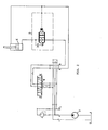
- Fig. 2 shows a circuit diagram with a piston K, a lowering brake check valve S, a directional control valve W and a supply device V.
- the top of the piston is connected directly to the directional control valve and the underside to the brake lock valve. By switching the directional valve, pressure can optionally be brought from the supply device to the top or to the bottom of the piston.
- the top of the piston is also connected to the X port of the counterbalance lock valve.
- the counterbalance check valve flows from A to B.
- the counterbalance check valve works as a check valve and, as described above, the check sleeve is moved back against the opposing spring forces depending on the pressure applied.
Landscapes
- Engineering & Computer Science (AREA)
- General Engineering & Computer Science (AREA)
- Mechanical Engineering (AREA)
- Physics & Mathematics (AREA)
- Fluid Mechanics (AREA)
- Safety Valves (AREA)
Applications Claiming Priority (2)
| Application Number | Priority Date | Filing Date | Title |
|---|---|---|---|
| DE8414265U | 1984-05-10 | ||
| DE8414265 | 1984-05-10 |
Publications (1)
| Publication Number | Publication Date |
|---|---|
| EP0163771A2 true EP0163771A2 (de) | 1985-12-11 |
Family
ID=6766720
Family Applications (1)
| Application Number | Title | Priority Date | Filing Date |
|---|---|---|---|
| EP84115881A Withdrawn EP0163771A2 (de) | 1984-05-10 | 1984-12-20 | Senkbrems-Sperrventil |
Country Status (2)
| Country | Link |
|---|---|
| EP (1) | EP0163771A2 (da) |
| DK (1) | DK1985A (da) |
Cited By (6)
| Publication number | Priority date | Publication date | Assignee | Title |
|---|---|---|---|---|
| EP0505349A3 (en) * | 1991-03-20 | 1993-03-03 | Hoerbiger Fluidtechnik Gmbh | Hydraulic actuator |
| WO1996021817A1 (en) * | 1995-01-12 | 1996-07-18 | Danfoss A/S | Two-way seat-type valve |
| WO1998021486A1 (de) * | 1996-11-11 | 1998-05-22 | Mannesmann Rexroth Ag | Rückschlagventilanordnung |
| WO1998021484A1 (de) * | 1996-11-11 | 1998-05-22 | Mannesmann Rexroth Ag | Ventilanordnung und verfahren zur ansteuerung einer derartigen ventilanordnung |
| DE19608801C2 (de) * | 1996-03-07 | 2000-06-08 | Oil Control Gmbh | Hydraulisches Lasthalte- bzw. Senkbremsventil |
| DE102004011485B4 (de) * | 2004-03-09 | 2013-04-25 | Linde Material Handling Gmbh | Hydraulische Ventileinrichtung |
-
1984
- 1984-12-20 EP EP84115881A patent/EP0163771A2/de not_active Withdrawn
-
1985
- 1985-01-02 DK DK1985A patent/DK1985A/da not_active Application Discontinuation
Cited By (11)
| Publication number | Priority date | Publication date | Assignee | Title |
|---|---|---|---|---|
| EP0505349A3 (en) * | 1991-03-20 | 1993-03-03 | Hoerbiger Fluidtechnik Gmbh | Hydraulic actuator |
| AT402334B (de) * | 1991-03-20 | 1997-04-25 | Hoerbiger Gmbh | Hydraulische zylinder/kolben-anordnung |
| WO1996021817A1 (en) * | 1995-01-12 | 1996-07-18 | Danfoss A/S | Two-way seat-type valve |
| GB2311591A (en) * | 1995-01-12 | 1997-10-01 | Danfoss As | Two-way seat-type valve |
| GB2311591B (en) * | 1995-01-12 | 1998-11-04 | Danfoss As | Two-way seat-type valve |
| DE19608801C2 (de) * | 1996-03-07 | 2000-06-08 | Oil Control Gmbh | Hydraulisches Lasthalte- bzw. Senkbremsventil |
| WO1998021486A1 (de) * | 1996-11-11 | 1998-05-22 | Mannesmann Rexroth Ag | Rückschlagventilanordnung |
| WO1998021484A1 (de) * | 1996-11-11 | 1998-05-22 | Mannesmann Rexroth Ag | Ventilanordnung und verfahren zur ansteuerung einer derartigen ventilanordnung |
| US6196247B1 (en) | 1996-11-11 | 2001-03-06 | Mannesmann Rexroth Ag | Valve assembly and method for actuation of such a valve assembly |
| US6223773B1 (en) * | 1996-11-11 | 2001-05-01 | Mannesmann Rexroth Ag | Check valve assembly |
| DE102004011485B4 (de) * | 2004-03-09 | 2013-04-25 | Linde Material Handling Gmbh | Hydraulische Ventileinrichtung |
Also Published As
| Publication number | Publication date |
|---|---|
| DK1985A (da) | 1985-11-11 |
| DK1985D0 (da) | 1985-01-02 |
Similar Documents
| Publication | Publication Date | Title |
|---|---|---|
| EP0197467B1 (de) | Leckfreies Brems-Sperrventil | |
| DE69105851T2 (de) | Einrichtung zur Steuerung hydraulischer Motoren. | |
| DE2352742C2 (de) | Hydraulisches Senkbrems-Sperrventil | |
| EP0650558B1 (de) | Steueranordnung für mindestens einen hydraulischen verbraucher | |
| EP1106841A2 (de) | Linearverstellantrieb | |
| DE2513013A1 (de) | Hydraulisches wegeventil zur steuerung des druckmittelflusses zu und von einem doppelseitig beaufschlagbaren hydraulikzylinder | |
| EP0163771A2 (de) | Senkbrems-Sperrventil | |
| AT402334B (de) | Hydraulische zylinder/kolben-anordnung | |
| EP0051201A1 (de) | Kupplung für Hydrauliksysteme | |
| DE19608801A1 (de) | Hydraulisches Lasthalte- bzw. Senkbremsventil | |
| DE2718190C2 (de) | Hydraulische Kolben-Zylinder-Anordnung zum Kippen des Fahrerhauses eines Lastkraftwagens | |
| DE2833924A1 (de) | Hydraulische schaltgruppe | |
| DE3532591A1 (de) | Hydraulische vorrichtung, insbesondere 2-wege-proportionaldrosselventil | |
| DE8414265U1 (de) | Senkbrems-Sperrventil | |
| DE2932523C2 (de) | Hydraulisch entsperrbares Sitzventil | |
| DE29710127U1 (de) | Elektrohydraulische Spannvorrichtung | |
| EP0717201B1 (de) | Schutzsystem für eine Druckmittelanlage | |
| DE2833971C2 (de) | Leitungsbruchsicherungs-Vorrichtung zur Anordnung zwischen einem hydraulischen Steuergerät und wenigstens einem Arbeitszylinder | |
| AT516317B1 (de) | Hydraulische Schaltung zur Versorgung eines Verbrauchers mit Differentialcharakter | |
| DD232533A5 (de) | Hydraulisches betaetigungsglied zur steuerung von ventilen | |
| DE60010641T2 (de) | Überdruckventil | |
| EP0437717B1 (de) | Sitzventil | |
| DE3411063C2 (da) | ||
| DE102019207539A1 (de) | Absperr- und Sicherheitsblock | |
| DD150008B1 (de) | Selbstschliessendes absperrventil fuer hohe druecke |
Legal Events
| Date | Code | Title | Description |
|---|---|---|---|
| PUAI | Public reference made under article 153(3) epc to a published international application that has entered the european phase |
Free format text: ORIGINAL CODE: 0009012 |
|
| AK | Designated contracting states |
Designated state(s): BE CH DE FR GB IT LI NL SE |
|
| STAA | Information on the status of an ep patent application or granted ep patent |
Free format text: STATUS: THE APPLICATION IS DEEMED TO BE WITHDRAWN |
|
| 18D | Application deemed to be withdrawn |
Effective date: 19870101 |
|
| RIN1 | Information on inventor provided before grant (corrected) |
Inventor name: JILDERDA, JAN FEIKO Inventor name: KESSELER, GUENTER |