EP0163771A2 - Blocking valve for a load-lowering brake - Google Patents
Blocking valve for a load-lowering brake Download PDFInfo
- Publication number
- EP0163771A2 EP0163771A2 EP84115881A EP84115881A EP0163771A2 EP 0163771 A2 EP0163771 A2 EP 0163771A2 EP 84115881 A EP84115881 A EP 84115881A EP 84115881 A EP84115881 A EP 84115881A EP 0163771 A2 EP0163771 A2 EP 0163771A2
- Authority
- EP
- European Patent Office
- Prior art keywords
- spring
- control piston
- control
- valve
- check valve
- Prior art date
- Legal status (The legal status is an assumption and is not a legal conclusion. Google has not performed a legal analysis and makes no representation as to the accuracy of the status listed.)
- Withdrawn
Links
Images

Classifications
-
- F—MECHANICAL ENGINEERING; LIGHTING; HEATING; WEAPONS; BLASTING
- F15—FLUID-PRESSURE ACTUATORS; HYDRAULICS OR PNEUMATICS IN GENERAL
- F15B—SYSTEMS ACTING BY MEANS OF FLUIDS IN GENERAL; FLUID-PRESSURE ACTUATORS, e.g. SERVOMOTORS; DETAILS OF FLUID-PRESSURE SYSTEMS, NOT OTHERWISE PROVIDED FOR
- F15B11/00—Servomotor systems without provision for follow-up action; Circuits therefor
- F15B11/003—Systems with load-holding valves
-
- F—MECHANICAL ENGINEERING; LIGHTING; HEATING; WEAPONS; BLASTING
- F15—FLUID-PRESSURE ACTUATORS; HYDRAULICS OR PNEUMATICS IN GENERAL
- F15B—SYSTEMS ACTING BY MEANS OF FLUIDS IN GENERAL; FLUID-PRESSURE ACTUATORS, e.g. SERVOMOTORS; DETAILS OF FLUID-PRESSURE SYSTEMS, NOT OTHERWISE PROVIDED FOR
- F15B13/00—Details of servomotor systems ; Valves for servomotor systems
- F15B13/01—Locking-valves or other detent i.e. load-holding devices
- F15B13/015—Locking-valves or other detent i.e. load-holding devices using an enclosed pilot flow valve
-
- F—MECHANICAL ENGINEERING; LIGHTING; HEATING; WEAPONS; BLASTING
- F16—ENGINEERING ELEMENTS AND UNITS; GENERAL MEASURES FOR PRODUCING AND MAINTAINING EFFECTIVE FUNCTIONING OF MACHINES OR INSTALLATIONS; THERMAL INSULATION IN GENERAL
- F16K—VALVES; TAPS; COCKS; ACTUATING-FLOATS; DEVICES FOR VENTING OR AERATING
- F16K15/00—Check valves
- F16K15/18—Check valves with actuating mechanism; Combined check valves and actuated valves
-
- F—MECHANICAL ENGINEERING; LIGHTING; HEATING; WEAPONS; BLASTING
- F15—FLUID-PRESSURE ACTUATORS; HYDRAULICS OR PNEUMATICS IN GENERAL
- F15B—SYSTEMS ACTING BY MEANS OF FLUIDS IN GENERAL; FLUID-PRESSURE ACTUATORS, e.g. SERVOMOTORS; DETAILS OF FLUID-PRESSURE SYSTEMS, NOT OTHERWISE PROVIDED FOR
- F15B2211/00—Circuits for servomotor systems
- F15B2211/50—Pressure control
- F15B2211/505—Pressure control characterised by the type of pressure control means
- F15B2211/50509—Pressure control characterised by the type of pressure control means the pressure control means controlling a pressure upstream of the pressure control means
- F15B2211/50545—Pressure control characterised by the type of pressure control means the pressure control means controlling a pressure upstream of the pressure control means using braking valves to maintain a back pressure
Landscapes
- Engineering & Computer Science (AREA)
- General Engineering & Computer Science (AREA)
- Mechanical Engineering (AREA)
- Physics & Mathematics (AREA)
- Fluid Mechanics (AREA)
- Safety Valves (AREA)
Abstract
Description
Die Erfindung betrifft ein Senkbrems-Sperrventil zur lastunabhängigen hydraulischen Steuerung mit einem Gehäuse, in dem Gehäuse vorgesehenen Betriebsanschlüssen, die in einer Richtung gegen die Federkraft einer im Inneren des Gehäuses angeordneten Verschlußanordnung und in der entgegengesetzten Richtung durch einen über einen Steueranschluß mit der Verschlußanordnung in Verbindung stehenden gegen die Verschlußanordnung wirkenden Aufsteuerkolben verbindbar sind, mit einem mit dem der Verbraucherseite zugeordneten Betriebsanschluß verbundenen Ringraum, der durch eine zur Verschlußanordnung gehörende Kolbenanordnung zum der Versorgerseite zugeordneten Betriebsanschluß hin verschließbar und öffenbar ist, wobei die Kolbenanordnung einen Steuerkolben aufweist, der eine Längsdurchgangsbohrung enthält, in der ein federbelastetes Ventil die hydraulische Vorentlastungsöffnung zum Versorgeranschluß verschließt, das mit Hilfe des Aufsteuerkolbens öffenbar ist, sowie mit einem an dem der Vorentlastungsöffnung abgekehrten Ende in der Kolbenanordnung angeordneten Federraum. Derartige Ventile werden zur Bewegung und zum Halten beispielsweise von Kränen eingesetzt.The invention relates to a lowering brake check valve for load-independent hydraulic control with a housing, operating connections provided in the housing, which in one direction against the spring force of a locking arrangement arranged inside the housing and in the opposite direction by a control connection to the locking arrangement in connection standing against the breech arrangement control piston can be connected, with an annular space connected to the service port assigned to the consumer side, which can be closed and opened by a breech assembly belonging to the breech assembly to the service side associated service port, the piston assembly having a control piston which contains a longitudinal through-bore, in which a spring-loaded valve closes the hydraulic preload opening to the supply connection, which can be opened with the aid of the control piston, and with one on the preload End opening remote end arranged in the piston assembly spring chamber. Such valves are used to move and hold cranes, for example.
Es sind derartige Senkbrems-Sperrventile bekannt, bei denen jedoch das federbelastete Ventil, das die hydraulische Vorentlastung besorgt, aus einem Hilfskolben besteht, an den die Feder, die sich am anderen Ende des Federraums abstützt, angreift. Beim Verschließen der Durchflußöffnung im ungesteuerten Betrieb wird über diesen Hilfskolben der Hauptkolben mitbewegt. Im gesteuerten Betrieb wirkt der Steuerdruck zuerst gegen diese Hilfskolbenfeder und bewegt den Hilfskolben innerhalb des Hauptkolbens. Dabei wird die zuvor bestehende Verbindung zwischen Federraum und Verbraucheranschluß geschlossen und es erfolgt eine hydraulische Vorentlastung. Anschließend wirkt der Steuerdruck zusätzlich gegen eine Schleppkolbenfeder, die auf der anderen Seite des Ringraumes angeordnet ist.Lowering check valves of this type are known, in which, however, the spring-loaded valve, which provides the hydraulic preload, consists of an auxiliary piston to which the spring, which is supported at the other end of the spring chamber, engages. When the flow opening is closed in uncontrolled operation, the main piston is also moved over this auxiliary piston. In controlled operation, the control pressure first acts against this auxiliary piston spring and moves the auxiliary piston within the main piston. The previously existing connection between the spring chamber and the consumer connection is closed and there is a hydraulic preload. The control pressure then also acts against a trailing piston spring which is arranged on the other side of the annular space.
Wenn das Ventil im gesteuerten Betrieb geöffnet ist, wird es, sofern ein Rohrbruch auf der Verbraucherseite erfolgt, sich beim Absenken der Last ordnungsgemäß verhalten. Im Falle eines Bruchs der Hilfskolbenfeder und bei Abfall des Steuerdruckes, kann das Ventil nicht schließen. Bricht die Schleppkolbenfeder, so hat in diesem Betriebsfall die Hilfskolbenfeder den Aufsteuerkolben gegen den anliegenden öldruck zu bewegen.If the valve is open in controlled operation, if there is a pipe break on the consumer side, it will behave properly when the load is lowered. If the auxiliary piston spring breaks and the control pressure drops, the valve cannot close. If the trailing piston spring breaks, the auxiliary piston spring has to move the pilot piston against the applied oil pressure in this operating case.
Diese Ventile haben den Nachteil, daß sie in ihrer Funktion lastabhängig sind, durch eine dynamische Dichtung zur Leckage neigen und im Falle eines Federbruchs zum unkontrollierten Abfallen der Last führen.The disadvantage of these valves is that their function is load-dependent, they tend to leak due to a dynamic seal and, in the event of a spring break, lead to an uncontrolled drop in the load.
Der vorliegenden Erfindung liegt die Aufgabe zugrunde, ein Senkbrems-Sperryentil zu schaffen, das im Normalbetrieb und bei Störungen in den Zuleitungen und bei Federbrüchen im Inneren des Ventils einen sicheren Betrieb erlaubt, indem die Last entweder weiter gesteuert oder in ihrem Zustand gehalten werden kann.The present invention has for its object to provide a counterbalance lock y entil that allows safe operation in normal operation and in the event of malfunctions in the supply lines and spring breaks inside the valve by either controlling the load further or keeping it in its state can.
Die Aufgabe für ein Senkbrems-Sperrventil der eingangs charakterisierten Art wird erfindungsgemäß dadurch gelöst, daß der Ringraum über eine Rückführbohrung, in der eine Drosseleinrichtung angeordnet ist, mit dem Federraum unverschließbar verbunden ist. Vorteilhafterweise ist die Drosseleinrichtung als Düse ausgebildet.The task for an over-center lock valve of the above-characterized A rt is inventively achieved in that the annular space through a return hole is disposed in a throttle device, is connected non-closable with the spring chamber. The throttle device is advantageously designed as a nozzle.
Es ist für die vorliegende Erfindung besonders wesentlich, daß eine andauernde Verbindung zwischen Ringraum und Federraum gegeben ist. Diese Verbindung wird durch eine Rückführbohrung im Inneren des Gehäuses sichergestellt. Grundsätzlich sind auch andere Verbindungsmöglichkeiten, die direkt von dem Verbraucheranschluß aus eine Verbindung zwischen Verbraucher- oder Lastseite mit dem Federraum herstellen, möglich. Für die gesamte Funktion des Senkbrems-Sperrventils muß nur sichergestellt sein, daß im Federraum ein Druck, der durch die Lastseite gesteuert wird, aufbaubar ist. Um eine hydraulische Vorentlastung für den gesteuerten Betrieb zu erreichen, muß in der Rückführverbindung eine Drosselung vorgesehen sein, die einen geringeren Zufluß von Öl erlaubt, als zum Abfließen durch das Vorentlastungsventil freigegeben wird. Dies kann durch eine einstellbare Drossel oder eine Düse erreicht werden. Durch die Verwendung einer Düse als Drosseleinrichtung kann abhängig vom Aufbau des Ventils die Drosselung durch die entsprechende Düse beeinflußt werden. Dies ist notwendig, da sonst das Ventil nicht mehr lastunabhängig arbeiten kann.It is particularly important for the present invention that there is an ongoing connection between the annular space and the spring space. This connection is ensured by a return hole in the interior of the housing. In principle, other connection options are also possible which establish a connection between the consumer or load side with the spring chamber directly from the consumer connection. For the entire function of the lowering brake check valve, it only has to be ensured that a pressure that is controlled by the load side can be built up in the spring chamber. In order to achieve a hydraulic pre-relief for the controlled operation, a restriction must be provided in the return connection, which allows a lower inflow of oil than is released for outflow through the pre-relief valve. This can be achieved with an adjustable throttle or a nozzle. By using a nozzle as a throttling device, the throttling can be influenced by the corresponding nozzle depending on the structure of the valve. This is necessary because otherwise the valve can no longer work independently of the load.
Gemäß einer weiteren vorteilhaften Ausgestaltung des erfindungsgemäßen Ventils stützt sich die Vorentlastungsventilfeder an dem der Vorentlastungsöffnung abgekehrten Ende des Steuerkolbens ab und eine Steuerkolbenfeder ist zwischen dem dem Ringraum abgekehrten Ende des Steuerkolbens und dem entgegengesetzten Ende des Federraumes angeordnet.According to a further advantageous embodiment of the valve according to the invention, the pre-relief valve spring is supported on the end of the control piston facing away from the pre-relief opening and a control piston spring is arranged between the end of the control piston facing away from the annular space and the opposite end of the spring space.
Durch diese Konstruktion wird erreicht, daß die Vorentlastungsventilfeder nur für die hydraulische Vorentlastung verwendet wird und somit auch nur dafür ausgelegt zu sein braucht. Die Steuerkolbenfeder wirkt als Gegenkraft für den Druck auf den Steuerkolben. Dadurch kann bei einem Bruch der Steuerkolbenfeder bei ungesteuertem Betrieb durch das geschlossene Vorentlastungsventil der Steuerkolben durch den über die Rückführverbindung ermöglichten Druckaufbau im Federraum schließen. Im gesteuerten Betrieb wird bei einem Bruch der Steuerkolbenfeder die Vorentlastungsventilfeder das Vorentlastungsventil bei abnehmendem Ansteuerdruck am Steueranschluß schließen und die Entlastung des Federraums beenden. Im nachfolgenden baut sich dann über die Rückführverbindung ebenfalls ein Druck im Federraum auf, der in der Lage ist, die öffnung durch den Steuerkolben zu verschließen. Durch konstruktive Ausgestaltung kann auch bei einem Bruch der Vorentlastungsventilfeder ein Schließen des Vorentlastungsventils besorgt werden. Ohne einen Federbruch erfolgt die Schließbewegung mechanisch-hydraulisch.This construction ensures that the previous Load valve spring is only used for hydraulic pre-relief and therefore only needs to be designed for it. The control piston spring acts as a counterforce for the pressure on the control piston. As a result, if the control piston spring breaks during uncontrolled operation due to the closed pre-relief valve, the control piston can close due to the pressure build-up in the spring chamber made possible by the return connection. In controlled operation, if the control piston spring breaks, the pre-relief valve spring will close the pre-relief valve as the control pressure at the control connection decreases and stop relieving the spring chamber. In the following, a pressure also builds up in the spring chamber via the return connection, which pressure is able to close the opening by the control piston. Due to the design, even if the pre-relief valve spring breaks, the pre-relief valve can be closed. Without a broken spring, the closing movement takes place mechanically and hydraulically.
Zweckmäßigerweise wird zusätzlich ein Rückschlagventil in der Verschlußordnung integriert, das ein schnelles Freigeben der Öffnung zwischen dem Verbraucher und Versorgung im ungesteuerten Betrieb erlaubt und als Umgehungsventil für das Steuerventil wirkt. Dies wird vorteilhafterweise dadurch erreicht, daß um den Steuerkolben konzentrisch eine Rückschlaghülse mit Verbindungsöffnungen zum Ringraum hin angeordnet ist. Zweckmäßigerweise weist die Rückschlaghülse eine Mitnehmereinrichtung für den Steuerkolben und der Steuerkolben eine Mitnehmereinrichtung für die Rückschlaghülse auf. Die Rückschlaghülse muß zur Funktion Verbindungsöffnungen zum Ringraum aufweisen, damit im gesteuerten Betrieb, in dem die Rückschlaghülse im Ruhezustand bleibt, über die Öffnung zwischen dem Steuerkolben und der Rückschlaghülse die Verbindung zwischen Verbraucher und Versorger hergestellt werden kann. Im ungesteuerten Betrieb wird durch den Druck über den Versorgungsanschluß die Rückschlaghülse aus der Schließstellung herausbewegt und ermöglicht den Durchfluß der Flüssigkeit zum Verbraucher hin. Der Steuerkolben wird einschließlich Vorentlastungsventil durch den inneren Anschlag der Mitnehmereinrichtung mitgenommen, so daß ein größerer öffnungsquerschnitt freigegeben wird. Der Schließvorgang kann allein durch die Steuerkolbenfeder erfolgen, da in umgekehrter Richtung die Rückschlaghülse durch den Steuerkolben zwangsgesteuert ist. Der Steuerkolben weist im Bereich des dem Ringraum zugekehrten Endes eine die Mitnehmereinrichtung bildende Sitzfläche auf. Diese Sitzfläche kann als Mitnehmer und als Anschlag dienen, wobei die Ausgestaltung im Rahmen der dem Fachmann geläufigen Überlegungen variiert werden kann.A check valve is expediently also integrated in the closure arrangement, which allows the opening between the consumer and supply in uncontrolled operation to be released quickly and acts as a bypass valve for the control valve. This is advantageously achieved in that a non-return sleeve with connecting openings to the annular space is arranged concentrically around the control piston. The check sleeve expediently has a driver device for the control piston and the control piston has a driver device for the check sleeve. The check sleeve must have connection openings to the annulus to function, so that in controlled operation, in which the check sleeve remains in the idle state, the connection between consumer and supplier can be established via the opening between the control piston and the check sleeve. In uncontrolled operation, there is a setback due to the pressure via the supply connection sleeve moved out of the closed position and allows the flow of liquid to the consumer. The control piston, including the pre-relief valve, is carried along by the inner stop of the driver device, so that a larger opening cross section is released. The closing process can be carried out solely by the control piston spring, since the check sleeve is positively controlled by the control piston in the opposite direction. In the region of the end facing the annular space, the control piston has a seat surface which forms the driver device. This seat can serve as a driver and as a stop, the design being able to be varied within the framework of the considerations familiar to the person skilled in the art.
Zweckmäßigerweise ist zwischen dem dem Ringraum abgekehrten Ende der Rückschlaghülse und dem entgegengesetzten Ende des Federraumes eine Rückschlagfeder angeordnet. Diese Feder unterstützt die Schließbewegung der Rückschlaghülse, so daß das Schließen von der Durchflußöffnung mittels Rückschlagfeder und Steuerkolbenfeder durchgeführt wird. Beim Bruch der Rückschlagfeder kann der Verschluß durch die oben erwähnte Zwangssteuerung der Rückschlaghülse durch den Steuerkolben erfolgen. Bei dem Bruch der Steuerkolbenfeder geschieht das Schließen durch den Druck in der Federkammer. Die Rückschlagfeder kann sich selbstverständlich auch an einem im Federraum angeordneten Absatz oder ähnlichem abstützen.A check spring is expediently arranged between the end of the check sleeve facing away from the annular space and the opposite end of the spring area. This spring supports the closing movement of the check sleeve, so that the closing of the flow opening is carried out by means of a check spring and a control piston spring. If the non-return spring breaks, the closure can take place through the above-mentioned positive control of the non-return sleeve by the control piston. If the control piston spring breaks, it is closed by the pressure in the spring chamber. The non-return spring can of course also be supported on a shoulder or the like arranged in the spring chamber.
Die Rückschlaghülse weist vorzugsweise eine dem Versorgeranschluß zugekehrte Druckfläche und eine gegen die Gehäuseinnenwand zum Ringraum hin abdichtende Dichtfläche auf. Der Steuerkolben ist an seinem die öffnung zwischen Steuerkolben und Rückschlaghülse abdichtenden Ende vorteilhafterweise mit Steuerschlitzen versehen. Die Rückschlaghülse ist so ausgebildet, daß ein Verbraucherrückdruck nicht in der Lage ist, das Rückschlagventil ungewollt zu öffnen, da eine Differenzfläche fehlt.The non-return sleeve preferably has a pressure surface facing the supply connection and a sealing surface sealing against the inner wall of the housing towards the annular space. The control piston is advantageously provided with control slots at its end sealing the opening between the control piston and the check sleeve. The check sleeve is designed in such a way that a consumer back pressure is unable to unintentionally check the check valve to open because there is no difference surface.
Die Ausgestaltung im Bereich der Durchflußöffnung von Versorgeranschluß zu Verbraucheranschluß dient im ungesteuerten Betrieb der schnellen öffnung bei Überschreiten eines durch die Federkräfte vorgegebenen Druckes und der sicheren leckfreien Abdichtung. Im Bereich der Durchflußöffnung von Verbraucheranschluß zu Versorgeranschluß dient die Ausgestaltung der Freigabe und dem Schließen des Rückschlaghülseninnenraums durch Steuerschlitze, entsprechend dem Ansteuerdruck und der Federgegenkräfte.The configuration in the area of the flow opening from the supply connection to the consumer connection serves for the uncontrolled operation of the quick opening when a pressure predetermined by the spring forces is exceeded and the safe leak-free sealing. In the area of the flow opening from the consumer connection to the supply connection, the design serves for the release and the closing of the non-return sleeve interior through control slots, corresponding to the actuation pressure and the spring counterforce.
Die Anschrägung der Sitzflächen der einzelnen Ventile, d.h. die Dichtflächen zwischen Gehäuse und Rückschlaghülse, Rückschlaghülse und Steuerkolben und Steuerkolben und Vorentlastungsventilkugel beträgt vorteilhafterweise ca. 45°. Durch diese ausgewählte Anschrägung wird fertigungstechnisch eine bessere Anpassung der Flächen aneinander und eine sichere Abdichtung erreicht. Außerdem können dadurch andere Ventilparameter entsprechend den Erfordernissen angepaßt werden.The chamfer of the seat surfaces of the individual valves, i.e. the sealing surfaces between the housing and non-return sleeve, non-return sleeve and control piston and control piston and pre-relief valve ball is advantageously approximately 45 °. Through this selected bevel, a better adaptation of the surfaces to one another and a secure seal is achieved in terms of production technology. It also allows other valve parameters to be adjusted as required.
Das Steuerventil und das Rückschlagventil sind gemeinsam in einer Gehäusebohrung als Patronenventil integriert. Dies ermöglicht in der Praxis eine einfache Handhabung und erfordert weniger Platz.The control valve and the check valve are integrated in one housing bore as a cartridge valve. In practice, this enables easy handling and requires less space.
Für die Funktion des gesamten Ventils müssen selbstverständlich die dem Fachmann geläufigen Abmessungen der Räume, Bohrungen und Druckflächen gewählt werden.For the function of the entire valve, the dimensions of the spaces, bores and pressure areas familiar to the person skilled in the art must of course be selected.
Durch die vorliegende Erfindung wird in einem Gehäuse ein Senkbrems-Sperrventil mit einem Umgehungsrückschlagventil als Patronenventil geschaffen, das ein Steuerventil, bestehend aus dem Steuerkolben und den zugehörigen Teilen, und mit entsprechenden funktionsgerechtem Aufbau im Bereich der öffnung und der Sitzflächen, das durch ein das Steuerventil umgehendes Rückschlagventil, ebenfalls mit dem für die Funktion notwendigen Aufbau im Bereich der Durchflußöffnung und der Sitzflächen, aufweist, das selbst bei Bruch einzelner Federn bei Bedarf sicher schließt und ein Absinken der Last verhindert. Ein undefinierter Zustand des Ventils bei auftretenden Fehlern im Inneren wird dadurch vermieden und das Lecken ausgeschlossen.The present invention provides a counterbalance check valve with a bypass check valve as a cartridge valve in a housing, which has a control valve, consisting of the control piston and the associated parts, and with a corresponding functional design in the area the opening and the seat surfaces, which has a check valve that bypasses the control valve, also with the structure required for the function in the area of the flow opening and the seat surfaces, which closes securely when necessary, even if individual springs break, and prevents the load from falling. This avoids an undefined state of the valve in the event of internal faults and prevents leakage.
Ein weiterer Vorteil liegt im gesamten Aufbau, der eine Abstimmung des Ventils auf bestimmte gewünschte Betriebszustände und Eigenschaften ermöglicht. Dies kann durch die Auswahl und Abstimmung der Düse sowie der Federn erfolgen. Auch durch die Änderung des Kugeldurchmessers der das Vorentlastunsventil verschließenden Vorentlastungskugel kann die Funktion des Ventils beeinflußt werden. Durch die Anordnung aller Federn auf einer Seite der Durchflußöffnung und die Lastübernahme von nur einzelnen Federn in bestimmten Betriebszuständen ist eine zweckmäßige Dimensionierung der Federn möglich. So hat beispielsweise die Steuerkolbenfeder im gesteuerten Betrieb den Ansteuerdruck zu halten, während die Vorentlastungsventilfeder nur dem Vorentlastungsdruck entgegenwirkt. Im ungesteuerten Betrieb verteilt sich die Druckkraft auf die Steuerkolbenfeder und die Rückschlagfeder.Another advantage lies in the overall structure, which enables the valve to be adjusted to certain desired operating states and properties. This can be done by selecting and tuning the nozzle and springs. The function of the valve can also be influenced by changing the ball diameter of the pre-relief ball closing the pre-relief valve. The arrangement of all the springs on one side of the flow opening and the load transfer of only individual springs in certain operating states make it possible to dimension the springs appropriately. For example, the control piston spring has to maintain the actuation pressure in the controlled operation, while the pre-relief valve spring only counteracts the pre-relief pressure. In uncontrolled operation, the pressure force is distributed to the control piston spring and the return spring.
Ein Ausführungsbeispiel gemäß der vorliegenden Erfindung ist nachfolgend anhand der Fig. 1 beschrieben.An exemplary embodiment according to the present invention is described below with reference to FIG. 1.
Die Zeichnungen stellen dar:
- Fig. 1 einen Längsquerschnitt durch das erfindungsgemäße Ventil und
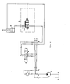
- Fig. 2 eine Schaltungsanordnung des Ventils.
- Fig. 1 shows a longitudinal cross section through the valve according to the invention and
- Fig. 2 shows a circuit arrangement of the valve.
Das in Fig. 1 dargestellte Senkbrems-Sperrventil ist als Patronenventil ausgebildet und besteht aus einem Gehäuse, das einen Ventilkörper 29 und einen Ventildeckel 28 aufweist. In dem Ventilkörper befindet sich ein Anschluß A und ein Anschluß B, der durch eine strichpunktierte kreisförmige Linie angedeutet ist. Zum Anschluß des Ventils an externe Versorgungsleitungen ist auf der Stirnseite der Ansteueranschluß X angeordnet. Der Anschluß A wird gemäß Fig. 2 extern mit einer Versorgungseinrichtung und der Anschluß B mit der Last bzw. dem Verbraucher verbunden. Der Anschluß A weist eine Vorkammer 23 und eine mit dieser Vorkammer in Verbindung stehende Hauptkammer 24 auf. In dem ausgeführten Ausführungsbeispiel ist an die Vorkammer 23 ein internes Wechselventil für Sonderfunktionen angeschlossen. Der Anschluß B steht mit einem im Inneren des Ventils angeordneten Ringraum 1 in Verbindung. Die Öffnung zwischen Ringraum 1 und Hauptkammer 24 ist durch eine Verschlußanordnung, die eine Kolbenanordnung mit Federn aufweist, verschlossen. Am X-Anschluß, der der Ansteuerung des Ventils dient, ist ein Aufsteuerkolben 7 vorgesehen, dessen eines Ende in die Hauptkammer 24 hereinragt und einen Stift 8 aufweist, der bewegbar in die Kolbenanordnung eingeführt ist. Bei am anderen Ende des Aufsteuerkolbens anliegendem Druck wird dieser in Richtung Kolbenanordnung bewegt, und dadurch eine Verbindung des Anschlusses A mit dem Anschluß B erreicht.The lowering brake check valve shown in FIG. 1 is designed as a cartridge valve and consists of a housing which has a
Die Verschlußanordnung weist eine Rückschlaghülse 9 auf, die konzentrisch einen Steuerkolben 10 umgibt. Im Inneren des Steuerkolbens ist in einer Längsbohrung an dem dem Stift 8 zugekehrten Ende eine hydraulische Vorentlastungskugel 12 angeordnet, die durch eine Kugelführung 13 und eine Rückschlagventilfeder 14, die sich an einem Federanschlag 15 am Ende des Steuerkolbens abstützt, die Längsbohrung verschließt. Der Steuerkolben 10 ragt in die Hauptkammer 24 hinein, ohne mit seiner Stirnseite die Stirnseite des Aufsteuerkolbens 7 zu berühren. Der Aufsteuerkolben 7 und die Kolbenanordnung sind entlang einer gemeinsamen Längsachse angeordnet. Im geschlossenen Zustand weist die Stirnseite des Steuerkolbens 10 einen Abstand von der Stirnseite des Aufsteuerkolbens 7 auf. Der Stift 8 ragt in den Teil der Längsbohrung des Steuerkolbens 10 hinein, der durch die hydraulische Vorentlastungskugel 12 verschlossen ist. Wenn sich aufgrund des am Anschluß X anliegenden Öldruckes der Aufsteuerkolben 7 in Richtung Steuerkolben 10 bewegt, wird die hydraulische Vorentlastungskugel 12 durch den Stift 8 gegen die Kraft der Vorentlastungsventilfeder 14 verschoben, so daß die Öffnung 20 zur Hauptkammer 24 freigegeben wird.The closure arrangement has a
Die um den Steuerkolben 10 angeordnete Rückschlaghülse 9 weist im Bereich des Ringraumes Öffnungen auf, so daß die im Ringraum 1 vorhandene Flüssigkeit direkt mit der Außenseite des Steuerkolbens 10 in Berührung steht. Der Steuerkolben 10 weist im Ringraumbereich eine Sitzfläche 22 auf, die als Anschlag für den Steuerkolben 10 sowie als Mitnehmereinrichtung für die Rückschlaghülse 9 in Richtung Ringraum 1 und für den Steuerkolben in Richtung Federraum 4 dient. Die Rückschlaghülse 9 wird an ihrem dem Ringraum 1 abgekehrten Ende durch eine Rückschlagfeder 33, sofern keine höhere Kraft aus der Hauptkammer 24 gegen die Hülse 9 wirkt, in ihrer Schließstellung gehalten. In gleicher Weise wird der Steuerkolben 10 durch eine Steuerkolbenfeder 32, die sich an dem dem Steuerkolbenende abgekehrten Ende des Federraumes 4 abstützt, gehalten. In diesem Ausführungsbeispiel stützt sich die Feder 33 nicht am Ende des Federraumes 4, sondern an einem im Federraum angeordneten Ansatz ab. Die Federn 32 und 33 sowie die Feder 14 sind alle auf einer Seite der Durchflußöffnung angeordnet und wirken alle der Wirkungsrichtung des Aufsteuerkolbens 7 entgegen. Ein Anschlag 34 für den Steuerkolben 10, der gleichzeitig als Führung für die Steuerkolbenfeder 32 dient, ragt von dem Ende, an dem sich auch die Kolbenfeder 32 abstützt, in den Federraum 4 konzentrisch hinein. Der Verschlußstopfen 31 verschließt eine aus konstruktiven Gründen vorgesehene Bohrung. Der Steuerkolben 10 weist an seinem der Feder zugekehrten Ende einen Federauflagering 17 auf.The
Die Dichtfläche 19 zwischen Gehäuse 29 und Rückschlaghülse 9 und die Dichtfläche 21 zwischen Rückschlaghülse 9 und Steuerkolben 10 weisen zur leckfreien Ausbildung des Ventils und zur besseren Herstellung eine Anschrägung von 45° auf. Auch die Dichtfläche 20 für die Vorentlastungsventilkugel 12 ist 45° abgeschrägt.The sealing
Der Ringraum 1 ist mit dem Federraum 4 über eine Rückführbohrung 5 verbunden. Aus konstruktiven Gründen mündet die Rückführbohrung 5 in eine von der Außenseite des Ventils zum Ringraum 1 gehende Bohrung. Diese Bohrung ist an der Außenseite durch eine Verschlußkappe 2 verschlossen. In der Rückführbohrung 5 ist eine Düse 40 angeordnet.The
In der Ruhestellung ist das gesamte Ventil geschlossen. Die . Rückschlaghülse 9, der Steuerkolben 10 sowie die hydraulische Vorentlastungskugel 12 werden durch die entsprechenden Federn 33, 32 und 14 mechanisch und durch den hydraulischen Druck in dem Federraum 4 zugehalten. Ein Durchfluß von A nach B oder B nach A ist nicht möglich.In the rest position, the entire valve is closed. The . Check
Wenn das Ventil von A nach B beispielsweise zum Heben einer Last durchströmt werden soll, wird der Flüssigkeitsstrom, normalerweise Öl, einen Druck im A-Kanal des Ventils aufbauen und in der Hauptkammer 24 gegen die Druckfläche 6 der Rückschlaghülse 9 drücken, so daß die Rückschlaghülse gegen die Federkraft der Rückschlaghülsenfeder 33 sich von der Dichtfläche 19 abhebt und damit eine öffnung zum Ringraum 1 und dem damit verbundenen Anschluß B freigibt. Durch den inneren Anschlag 22, der als eine Sitzfläche ausgebildet ist, wird der Steuerkolben 10 mitbewegt und je nach anliegendem Druck eine maximale Öffnung, die durch die Federkräfte der Federn 32 und 33 bestimmt wird, freigegeben. Sofern in diesem Betriebszustand die Rückschlaghülsenfeder 33 bricht, kann der Durchfluß von A nach B durch die Mitnahmewirkung des Steuerkolbens 10 und die Federkraft der Feder 32 beeinflußt und beendet werden. Bei einem Bruch der Steuerkolbenfeder 32 sorgt der im Federraum vorliegende Druck für das Verschließen der öffnung 21. Die Vorentlastungsfeder 14 bleibt in ihrem Ruhezustand.If the valve is to be flowed through from A to B, for example for lifting a load, the liquid flow, normally oil, will build up pressure in the A-channel of the valve and press in the
Soll ein Durchfluß von B nach A erreicht werden, so muß in der Aufsteuerleitung X ein Druck erzeugt werden, der zunächst bewirkt, daß eine hydraulische Vorentlastung zwischen dem mit dem Federraum 4 über die Rückführung 5 in Verbindung stehenden Ringraum 1 und der Hauptkammer 24 erreicht wird. Die hydraulische Vorentlastung bewirkt, daß der Federraum 4 drucklos wird und nur noch die Steuerkolbenfeder 32 beim Steuern des Durchflusses von B nach A wirksam ist und somit das Ventil lastunabhängig arbeiten kann.If a flow from B to A is to be achieved, a pressure must be generated in the control line X, which initially has the effect that a hydraulic preloading between the
Der Aufsteuerkolben 7 wird durch die hydraulische Kraft in Richtung Kolbenanordnung bewegt, so daß der Stift 8 die Vorentlastungskugel 12 gegen die Vorentlastungsfeder 14 verschiebt und dadurch ein Querschnitt freigegeben wird, der größer ist als der der Düse 40, so daß eine einwandfreie Entlastung des Federraumes erfolgt. Durch Erhöhen des Druckes in der Aufsteuerleitung X stößt die Stirnfläche des Aufsteuerkolbens 7 gegen die Stirnfläche des Steuerkolbens 10 und verschiebt diesen gegen die Steuerkolbenfeder 32, so daß ein Durchfluß über die Steuerschlitze 25 am Steuerkolben 10 und über die Verbindungsöffnungen 3 in der Rückschlaghülse 9 von B nach A erfolgen kann. Entsprechend des Druckes in der Aufsteuerleitung X wird der Steuerkolben 10 auf den jeweiligen beeinflußbaren Durchfluß bis zum maximalen Anschlag 34 geöffnet.The
Im Falle eines Rohrbruches im Kreislauf (Fig. 2) sinkt der Aufsteuerdruck in der X-Leitung, so daß die Federkräfte der Federn 14, 33 und 32 bewirken, daß das Schließen durch Drucköl, das über die Rückführung 5 und die Düse 40 zufließt, unterstützt wird. Im Falle eines Federbruches der Federn 32 und 33 ist diese Schließfunktion ebenfalls gewährleistet, da die Rückschlaghülse 9, wie bereits oben beschrieben, durch den Steuerkolben 10 zwangsgesteuert wird und diese durch die über die Rückführung 5 und die Düse 40 zufließende hydraulische Größe auf ihre Sitze gedrückt wird. Bei einem Versagen der Vorentlastungsventilfeder 14 wird durch die Konstruktion der Kugelführung 13, die eine Längsbohrung aufweist, die in eine Querbohrung mündet, durch den im Federraum herrschenden Druck die Vorentlastungskugel in ihre Verschlußstellung gebracht.In the event of a broken pipe in the circuit (FIG. 2), the pilot pressure in the X line drops, so that the spring forces of the
Fig. 2 zeigt eine Schaltskizze mit einem Kolben K, einem Senkbrems-Sperrventil S, einem Wegeventil W und einer Versorgungseinrichtung V. Die Oberseite des Kolbens ist direkt mit dem Wegeventil und die Unterseite mit dem Bremssperrventil verbunden. Durch Umschalten des Wegeventils kann wahlweise Druck von der Versorgungseinrichtung auf die Oberseite oder auf die Unterseite des Kolbens gebracht werden. Die Oberseite des Kolbens ist gleichzeitig mit dem X-Anschluß des Senkbrems-Sperrventils verbunden. Wenn der Kolben gehoben werden soll, erfolgt ein Durchfluß des Senkbrems-Sperrventils von A nach B. In diesem Fall arbeitet das Senkbrems-Sperrventil als Rückschlagventil und die Rückschlaghülse wird, wie vorstehend beschrieben, in Abhängigkeit des anliegenden Druckes gegen die entgegenwirkenden Federkräfte zurückbewegt. Beim Absenken des Kolbens ist die Durchflußrichtung von B nach A, wobei die von B nach A durchfließende ölmenge über den X-Anschluß gesteuert wird. Sobald sich der Kolben zu schnell abwärts bewegt, sinkt der Druck in der X-Ansteuerleitung, so daß das Senkbremsventil den Durchfluß von B nach A drosselt, und dadurch ein zu schnelles Absinken der Last verhindert. Sobald sich der Druck in der X-Leitung wieder aufbaut, wird das Senkbremsventil weiter geöffnet und ein schnelleres Absinken des Kolbens ist möglich. In der Schaltskizze ist zusätzlich noch ein Druckbegrenzungsventil eingezeichnet, das nur zur Sicherung der beispielsweise in der Versorgungseinrichtung vorhandenen Ölpumpe dient.Fig. 2 shows a circuit diagram with a piston K, a lowering brake check valve S, a directional control valve W and a supply device V. The top of the piston is connected directly to the directional control valve and the underside to the brake lock valve. By switching the directional valve, pressure can optionally be brought from the supply device to the top or to the bottom of the piston. The top of the piston is also connected to the X port of the counterbalance lock valve. When the piston is to be lifted, the counterbalance check valve flows from A to B. In this case, the counterbalance check valve works as a check valve and, as described above, the check sleeve is moved back against the opposing spring forces depending on the pressure applied. When the piston is lowered, the direction of flow is from B to A, the amount of oil flowing from B to A being controlled via the X connection. As soon as the piston moves downward too quickly, the pressure in the X control line drops, so that the lowering brake valve throttles the flow from B to A, and thereby increases prevents the load from dropping quickly. As soon as the pressure in the X line builds up again, the lowering brake valve is opened further and the piston can sink faster. A pressure relief valve is also shown in the circuit diagram, which is only used to secure the oil pump, for example, in the supply device.
Claims (12)
Applications Claiming Priority (2)
| Application Number | Priority Date | Filing Date | Title |
|---|---|---|---|
| DE8414265U | 1984-05-10 | ||
| DE8414265 | 1984-05-10 |
Publications (1)
| Publication Number | Publication Date |
|---|---|
| EP0163771A2 true EP0163771A2 (en) | 1985-12-11 |
Family
ID=6766720
Family Applications (1)
| Application Number | Title | Priority Date | Filing Date |
|---|---|---|---|
| EP84115881A Withdrawn EP0163771A2 (en) | 1984-05-10 | 1984-12-20 | Blocking valve for a load-lowering brake |
Country Status (2)
| Country | Link |
|---|---|
| EP (1) | EP0163771A2 (en) |
| DK (1) | DK1985A (en) |
Cited By (6)
| Publication number | Priority date | Publication date | Assignee | Title |
|---|---|---|---|---|
| EP0505349A2 (en) * | 1991-03-20 | 1992-09-23 | HOERBIGER FLUIDTECHNIK GmbH | Hydraulic actuator |
| WO1996021817A1 (en) * | 1995-01-12 | 1996-07-18 | Danfoss A/S | Two-way seat-type valve |
| WO1998021486A1 (en) * | 1996-11-11 | 1998-05-22 | Mannesmann Rexroth Ag | Check valve |
| WO1998021484A1 (en) * | 1996-11-11 | 1998-05-22 | Mannesmann Rexroth Ag | Valve system and manufacture of same |
| DE19608801C2 (en) * | 1996-03-07 | 2000-06-08 | Oil Control Gmbh | Hydraulic load holding or lowering brake valve |
| DE102004011485B4 (en) * | 2004-03-09 | 2013-04-25 | Linde Material Handling Gmbh | Hydraulic valve device |
-
1984
- 1984-12-20 EP EP84115881A patent/EP0163771A2/en not_active Withdrawn
-
1985
- 1985-01-02 DK DK1985A patent/DK1985A/en not_active Application Discontinuation
Cited By (12)
| Publication number | Priority date | Publication date | Assignee | Title |
|---|---|---|---|---|
| EP0505349A2 (en) * | 1991-03-20 | 1992-09-23 | HOERBIGER FLUIDTECHNIK GmbH | Hydraulic actuator |
| EP0505349A3 (en) * | 1991-03-20 | 1993-03-03 | Hoerbiger Fluidtechnik Gmbh | Hydraulic actuator |
| AT402334B (en) * | 1991-03-20 | 1997-04-25 | Hoerbiger Gmbh | HYDRAULIC CYLINDER / PISTON ARRANGEMENT |
| WO1996021817A1 (en) * | 1995-01-12 | 1996-07-18 | Danfoss A/S | Two-way seat-type valve |
| GB2311591A (en) * | 1995-01-12 | 1997-10-01 | Danfoss As | Two-way seat-type valve |
| GB2311591B (en) * | 1995-01-12 | 1998-11-04 | Danfoss As | Two-way seat-type valve |
| DE19608801C2 (en) * | 1996-03-07 | 2000-06-08 | Oil Control Gmbh | Hydraulic load holding or lowering brake valve |
| WO1998021486A1 (en) * | 1996-11-11 | 1998-05-22 | Mannesmann Rexroth Ag | Check valve |
| WO1998021484A1 (en) * | 1996-11-11 | 1998-05-22 | Mannesmann Rexroth Ag | Valve system and manufacture of same |
| US6196247B1 (en) | 1996-11-11 | 2001-03-06 | Mannesmann Rexroth Ag | Valve assembly and method for actuation of such a valve assembly |
| US6223773B1 (en) * | 1996-11-11 | 2001-05-01 | Mannesmann Rexroth Ag | Check valve assembly |
| DE102004011485B4 (en) * | 2004-03-09 | 2013-04-25 | Linde Material Handling Gmbh | Hydraulic valve device |
Also Published As
| Publication number | Publication date |
|---|---|
| DK1985D0 (en) | 1985-01-02 |
| DK1985A (en) | 1985-11-11 |
Similar Documents
| Publication | Publication Date | Title |
|---|---|---|
| EP0197467B1 (en) | Leak-free load control and holding valve | |
| DE2352742C2 (en) | Hydraulic lowering brake shut-off valve | |
| EP0650558B1 (en) | Control device for at least one hydraulic consumer | |
| DE3804846C2 (en) | Hydraulically unlockable check valve, especially for hydraulic expansion systems | |
| DE2513013A1 (en) | HYDRAULIC DIRECTIONAL VALVE FOR CONTROLLING THE FLOW OF PRESSURE FLOW TO AND FROM A DOUBLE-SIDED HYDRAULIC CYLINDER | |
| EP0163771A2 (en) | Blocking valve for a load-lowering brake | |
| EP0051201A1 (en) | Coupling for hydraulic systems | |
| DE19608801A1 (en) | Hydraulic load stop or braking valve | |
| AT402334B (en) | HYDRAULIC CYLINDER / PISTON ARRANGEMENT | |
| DE2718190C2 (en) | Hydraulic piston-cylinder arrangement for tilting the cab of a truck | |
| DE2833924A1 (en) | HYDRAULIC SWITCHING GROUP | |
| DE8414265U1 (en) | Lowering brake shut-off valve | |
| DE2932523C2 (en) | Hydraulically releasable seat valve | |
| DE3532591A1 (en) | HYDRAULIC DEVICE, IN PARTICULAR 2-WAY PROPORTIONAL THROTTLE VALVE | |
| EP0717201B1 (en) | Protection system in a pressure installation | |
| DE2833971C2 (en) | Line break safety device for arrangement between a hydraulic control unit and at least one working cylinder | |
| AT516317B1 (en) | Hydraulic circuit for supplying a consumer with differential character | |
| DE102019207539A1 (en) | Blocking and safety block | |
| DD232533A5 (en) | HYDRAULIC COMPONENT FOR CONTROLLING VALVES | |
| EP0437717B1 (en) | Seat valve | |
| DE3411063C2 (en) | ||
| DE102019219603B3 (en) | Valve module for a hydraulic tilting device of a solar panel carrier and solar panel carrier | |
| DE60010641T2 (en) | Pressure relief valve | |
| DD150008B1 (en) | SELF-RELATED SHUT-OFF VALVE FOR HIGH DRUCE | |
| DE4208298C2 (en) | Valve for limiting the lifting load on a hoist |
Legal Events
| Date | Code | Title | Description |
|---|---|---|---|
| PUAI | Public reference made under article 153(3) epc to a published international application that has entered the european phase |
Free format text: ORIGINAL CODE: 0009012 |
|
| AK | Designated contracting states |
Designated state(s): BE CH DE FR GB IT LI NL SE |
|
| STAA | Information on the status of an ep patent application or granted ep patent |
Free format text: STATUS: THE APPLICATION IS DEEMED TO BE WITHDRAWN |
|
| 18D | Application deemed to be withdrawn |
Effective date: 19870101 |
|
| RIN1 | Information on inventor provided before grant (corrected) |
Inventor name: JILDERDA, JAN FEIKO Inventor name: KESSELER, GUENTER |