EP0717201B1 - Protection system in a pressure installation - Google Patents
Protection system in a pressure installation Download PDFInfo
- Publication number
- EP0717201B1 EP0717201B1 EP95116660A EP95116660A EP0717201B1 EP 0717201 B1 EP0717201 B1 EP 0717201B1 EP 95116660 A EP95116660 A EP 95116660A EP 95116660 A EP95116660 A EP 95116660A EP 0717201 B1 EP0717201 B1 EP 0717201B1
- Authority
- EP
- European Patent Office
- Prior art keywords
- valve
- pressure
- consumer
- load circuit
- additional
- Prior art date
- Legal status (The legal status is an assumption and is not a legal conclusion. Google has not performed a legal analysis and makes no representation as to the accuracy of the status listed.)
- Expired - Lifetime
Links
Images

Classifications
-
- F—MECHANICAL ENGINEERING; LIGHTING; HEATING; WEAPONS; BLASTING
- F15—FLUID-PRESSURE ACTUATORS; HYDRAULICS OR PNEUMATICS IN GENERAL
- F15B—SYSTEMS ACTING BY MEANS OF FLUIDS IN GENERAL; FLUID-PRESSURE ACTUATORS, e.g. SERVOMOTORS; DETAILS OF FLUID-PRESSURE SYSTEMS, NOT OTHERWISE PROVIDED FOR
- F15B20/00—Safety arrangements for fluid actuator systems; Applications of safety devices in fluid actuator systems; Emergency measures for fluid actuator systems
Definitions
- the invention relates to a protection system according to the preamble of claim 1.
- the overflow valves of a protection system of the type mentioned kind usually have when filling the pressure medium system opening pressures different from atmospheric pressure, what inevitable manufacturing and adjustment tolerances is due. That can except for one uneven pressure build-up when filling the consumer circuit cause that in the event of a defect in the consumer circuit, whose overflow valve when filling the pressure medium system of atmospheric pressure the lower opening pressure, the total flow of Supply device in the defective consumer group and from this flows into the atmosphere and the intact Consumer group is not operational.
- the invention has for its object a protection system of the type mentioned above with simple means to train that it is both large and small Flow rates of the supply facility when intact Consumer circles an even pressure build-up and good filling safety in the event of a defective consumer circuit of the intact consumer group guaranteed.
- the invention enables a universally applicable Protection system and thereby a considerable rationalization effect.
- the invention is for pressure medium systems of the type mentioned Type for use in all technical fields and in connection with all liquid and gaseous Suitable for pressure media.
- Compressed air is often used as a pressure medium used.
- An important area of application in connection with compressed air offer vehicle pressure systems.
- the protection system mentioned at the beginning can be one or more additional overflow valves for one or more additional, compared to those in the preamble of the claim 1 mentioned original consumer groups subordinate, consumer groups are supplemented. This will below using the example of an additional overflow valve and an additional group of consumers. These statements apply to one or more further additional overflow valves and the assigned Consumer groups in full with.
- the overflow valve of the subordinate consumer circuit to the overflow valves of the original consumer groups arranged in parallel.
- the second option is the overflow valve of the additional consumer circuit the relief valves and the assigned Direct connections from the original consumer groups each one towards the additional Subordinate consumer circuit permeable check valve.
- a pressure medium system is given by a vehicle pressure medium system
- the original (and priority) consumer circles service brake circuits and their additional (and subordinate) Consumer circuit
- a spring-loaded parking brake circuit is when filling the pressure medium system from atmospheric pressure a certain performance of the service brake circuits is requested before the spring-loaded parking brake circuit sufficient pressure to release the spring brake having.
- Fig. 1 shows the solid lines schematically Basic version of a protection system for a pressure medium system with two consumer groups (10, 21), which by Storage containers are symbolized.
- the protection system contains for one consumer group (10) an overflow valve (4), a direct connection (29) and a shut-off device (12).
- the overflow valve (4) is between a supply device (1) and the Consumer group (10) arranged.
- the supply device (1) contains in a known manner a pressure generator and any necessary pressure treatment devices, Pressure control and pressure limiting devices.
- the direct connection (29) is bypassing the protective valve (4), i.e. parallel to this, also between the supply facility (1) and the consumer group (10) arranged.
- the overflow valve (4) and the direct connection (29) are connected to the supply device (1) connected via a supply line (2, 28).
- the shut-off device (12) is in the direct connection (29) arranged so that it controls their passage.
- the shut-off device (12) is not closer by means of two designated pressure-dependent control devices from two pressures controllable. Your is a control device via a control line (11) with one consumer circuit (10), their other control device is over one Control line (20) with the other consumer circuit (21) connected.
- the shut-off device (12) is designed that in the case of pressure equality, i.e. also at atmospheric pressure, the passage of the Direct connection (29) opens and this passage at one higher pressure in the control line (20) than in the Control line (11) closes. In other words: the shut-off device (12) is in favor of a pressure difference of the consumer group not assigned to it (21) into a direct connection passage (29) closing blocking position switched.
- the transmission capacity of the direct connections (26, 29) is so limited that in the event of a defect in one Consumer group (10 or 21) with every possible flow rate the supply device (1) in the defective Consumer circuit (10 or 21) flow rate in the assigned direct connection (29 or 26) one Back pressure creates the effect described below he brings.
- This limitation in transmission capacity by appropriate dimensioning of the direct connections, but also by throttling in the direct connections, such as they are indicated with the reference symbols (31 or 24), be achieved.
- Possible chokes can, like shown, upstream of the shut-off devices (12 or 19), but also arranged downstream of the same his.
- shut-off devices (12, 19) The inevitable unevenness of pressure build-up in consumer circles would be increased. This can be done through further training of the shut-off devices (12, 19) be that these only at a predetermined value of Pressure difference are switched into the blocking position. By this training will be pressure differences up to the predetermined one Value permitted, switching of the shut-off device (12 or 19) delayed accordingly, the one described Increase in the unevenness of the pressure build-up avoided.
- shut-off devices (12, 19) must this training be specially trained. Your switching must already be in the blocking position at the pressure difference insert that are caused by the dynamic pressure who - as described above - with a defective consumer group (10 or 21) in its direct connection (29 or 26) and in the intact consumer group (21 or 10) builds up. With increasing pressure difference the shut-off devices must be in the locked position continuously approach them until they reach the predetermined one Reach the pressure difference value. With others Words the shut-off devices (12, 19) in this Training for pressure differences below the predetermined Worth as continuously narrowing chokes be formed at the predetermined value of Pressure difference reach the (complete) blocking position. This training also builds up in this Case in the intact consumer group (26 or 29) to safely open the assigned overflow valve (23 or 4) leading consumer circuit pressure.
- shut-off devices (12 or 19) are trained in this way.
- the dashed line shows further developments of the Embodiment.
- Direct connections (29 or 26) can have auxiliary check valves (30 or 27) may be arranged.
- This Secondary check valve or these secondary check valves prevent that via the respectively assigned direct connection from the assigned consumer group (10th or 21) pressure medium to the supply device (1) or in the other consumer group (21 or 10) can flow.
- the - albeit very low - flow resistance of the secondary check valve (s) (30 or 27) causes an increase in the above-mentioned dynamic pressure and therefore affects the behavior of the protection system advantageous in the event of a defective consumer circuit pressure.
- the embodiment shows as further developments two arrangements of additional relief valves and these assigned additional consumer groups. These orders can exist alternatively, but also simultaneously his.
- this is additional Overflow valve (8) via an additional branch (5) in this case with (2, 5, 28) supply line between the supply device (1) and the associated additional consumer circuit (9) arranged.
- the additional overflow valve (8) and the associated one additional consumer groups (9) are suitable Measures compared to the original overflow valves (4, 23) and the assigned consumer groups (10, 21) subordinate, for example by one opposite the opening pressures of the overflow valves (4, 23) of the original Consumer groups (10, 21) increased opening pressure.
- the additional overflow valve (15) In the second arrangement of the additional overflow valve (15) are the original overflow valve (4) and the associated direct connection (29) a check valve (14) and the other original overflow valve (23) and the assigned direct connection (26) downstream of a check valve (18).
- the additional Overflow valve (15) with the outputs of the Check valves (14, 18) connected, and consequently between each check valve (14, 18) and the additional one Consumer circuit (17) arranged.
- the check valves (14, 18) are arranged so that they are in the direction of additional overflow valve (15) or the additional Consumer group (17) are permeable. In this arrangement receives the additional consumer group (17) Pressure medium, which was previously one of the original overflow valves (4, 23) or one of them Direct connections (29, 26) has happened.
- the additional overflow valve also in this arrangement (15) and the associated additional consumer group (17) compared to the original overflow valves (4, 23) and the assigned consumer groups (10.21) secondary.
- the opening pressure of the additional overflow valve (15) between the Pressure which is at its entrance when filling atmospheric pressure only set via direct connections can always be up to full or nominal pressure. In this arrangement it is determined by considerations who are not interested in the present context.
- Check valves (14, 18) are responsible for one (Back) flow from the additional consumer group (17) into the original consumer groups (10, 21), but also a (cross) flow between the original ones To prevent consumer groups (10, 21).
- the overflow valves (8, 15) are direct connections not provided. Such direct connections but are possible in a manner not shown and can by appropriate design of their flow capacity for Interpretation of subordination.
- the additional overflow valve can (8 or 15) and the respective assigned consumer group (9 or 17) for several additional consumer groups stand. This is due to broken off and with (7) or (13) designated lines indicated. In this case it can be appropriate, a cross flow between the additional Consumer circles through the relevant overflow valves upstream or downstream check valves prevent.
- check valves are with the reference numerals (6 or 16).
- the additional Overflow valve (s) which is a parallel arrangement to the original Overflow valves (4, 23)
- the original overflow valves (4, 23) can also Check valves (3, 25) are connected upstream or downstream, a backflow to the supply device (1) as well as a cross flow between the consumer circles, including roughly parallel additional ones, prevent.
- the illustration shows the protection system in dissolved form Construction.
- the existing overflow valves, the shutdown devices and the existing check valves are independent units and the associated ones Pressure medium lines and the existing direct connections, including the chokes, an open one Form line system.
- an overflow valve comes in any known suitable type of construction, z. B. according to the WABCO Westinghouse publication "Overflow valve 434 100", August 1973 edition.
- the there shown version "without backflow” includes an approximately assigned check valve.
- a shut-off device comes, for example, any suitable pressure difference controlled 2/2-way valve into consideration. The shut-off devices but must be linked so that one remains consistent when the other is in the locked position is.
- All components of the protection system can also be in compact design combined into a "multi-circuit protection valve" be and then form an assembly similar of those already mentioned in Fig. 3 DE 34 34 884 A1 is shown.
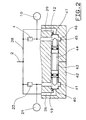
- Fig. 2 shows an embodiment of the shut-off devices (12 and 19).
- the housing (42) can Specially provided for the shut-off devices (12 and 19) but it can, in the case of the compact design of the protection system, including that common to all components Housing.
- each consumer circuit chamber (46 or 41) opens out the viewer's point of view, from the right or from the left one of the direct connections (29 or 26).
- the mouths Valve seats are surrounding in the housing in a known manner arranged. The following are simplicity for the sake of this valve seats labeled "mouth (s)".
- the mouths (47 and 40) of the direct connections to be understood in this way (29 and 26) are coaxial with each other.
- the consumer circuit chambers (41, 46) are through one Housing opening running coaxially to the mouths (40, 47) (43) connected to each other. Besides, they are Consumer circuit chambers (41, 46) each with one of the original consumer groups (10 or 21) and with the outlet of the assigned overflow valve (4th or 23) connected.
- each has its own unspecified, sealing element more common Design for sealing against each consumer circuit chamber (41 and 46) are provided.
- This type of sealing secures the consumer groups (10, 21) against each other from, as a penetrating approximately on a sealing element Leakage not in the other consumer group can cross, but via an unspecified breathing opening the housing opening (43) to the atmosphere, or, depending on the type of pressure medium, in a collection container can escape with atmospheric pressure.
- the sealing of the closing body can be based on this advantage (44) but can also be carried out with only one sealing element.
- the right end position of the Closing body (44) is by striking the Mouth (47) of the direct connection (29) determined.
- Corresponding is the left end position from the viewer's point of view of the closing body (44) is determined.
- the stop faces or stop lines of the closing body (44) are dimensional and formed from the material so that the closing body (44) over these areas or lines with the respective assigned mouth (47 or 40) of the direct connections (29 and 26) each form a valve (44, 47 or 44, 40), which is the passage between the respective direct connection (29 or 26) and the respective consumer circuit chamber (46 or 41) and thus the respective Consumer group (10 or 21) controlled. It's on hand that the mouths (47 and 40) of the material forth to form these valves (44, 47 and 44, 40) must be suitable.
- the consumer circuit pressure predominates in a consumer circuit chamber (46 or 41) the consumer circuit pressure in the other consumer circuit chamber (41 or 46), so moves the higher consumer circuit pressure the closing body (44) into the end position, which is defined by the mouth (40 or 47) the other consumer group (10 or 21) assigned direct connection (29 or 26) is determined. If the pressure in the consumer circuit chambers (41, 46), also at atmospheric pressure in the same the shooting body (44) has a central position releasing both valves one, but not necessarily the geometric Must be middle position.
- shut-off devices (12 or 19) 1 in a general form Shut-off devices as two pressure difference controlled Designate 2/2-way valves that are linked so that one is in its open position when that other is in its locked position.
- At least one shut-off device (12 or 19) only at a predetermined value of the pressure difference between the consumer circuit presses in their locked position, in which the relevant valve (44, 47 or 44, 40) is closed, is switched, for example by a switch spring (45).
- the switch spring (45) is supported on the one hand on the closing body (44) and on the other hand on the housing (42) and determined by their Force in the assigned end position of the closing body (44) the pressure difference at which the higher consumer circuit pressure the closing body against the force of the switching spring (45) has moved to this end position.
- the switch spring (45) is necessary to achieve the above-mentioned characteristic the continuously narrowing throttle in its spring characteristic be designed accordingly.
- Switch springs (45) are in the configuration described shown on both sides, but it can, if the Use case this requires, even on one side only Switch spring (45) may be provided.
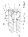
- FIG. 3 shows the example of, from the perspective of the viewer, on the right-hand side a training course on the design with switching spring (45) according to FIG. 2.
- the closing body (52) is favored by a pressure difference the consumer circuit pressure in the, not shown, connected to the other consumer group (21), Consumer circuit chamber (41) from the perspective of the beholder shifted to the right, shifts end facing the secondary valve member (54) against the secondary valve member (54), press this against the muzzle (47), thereby closes the auxiliary check valve (30) and keep it closed regardless of the pressures in the direct connection (29) and in the consumer circuit chamber (46).
- the closing spring (51) can be in a not shown Support way directly on the housing (42). In the illustration but is between the closing spring (51) and the housing (42) a spring plate (50) is arranged.
- the spring plate (50) is due to the switching spring (45). He offers a simple solution for simultaneous arrangement the closing spring (51) and the switching spring (45). is the closing body (52), as shown, in one Middle position, support both springs (45) and (51) on the spring plate (50) on the housing (42).
- the characteristic of the shut-off device (12) follows the advantage that the switching spring (45) is correspondingly weaker and thus be made cheaper and smaller can.
- the aforementioned gripping of the spring plate (50) by the Carrying shoulder (53) of the valve body (52) takes place, after doing an empty shift (x) Has.
- the empty shift (x) serves to compensate for any Manufacturing tolerances between the closing body (52) and Housing (42).
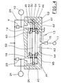
- the configuration according to FIG. 3 is a configuration trained, in which the for subordination of the additional overflow valve (15) and the associated one additional consumer group (17) required Check valves (14, 18) are integrated.
- the housing opening (43) in FIG. 2 and 3 to an additional consumer circuit chamber (64) trained.
- To form the additional consumer circuit chamber (64) is between the consumer circuit chamber (46) and the interior of the housing opening in the here with (65) designated housing the inside of the Breakthrough opening facing the valve seat (62) arranged, namely coaxial to the mouth (47) of the Direct connection (29) and thus also coaxial to the mouth (40) on the left, from the perspective of the beholder Page.
- the additional consumer circuit chamber (64) is one unspecified connection with the additional Additional consumer group (17) Overflow valve (15) connected to the inlet.
- an axially displaceable valve body (60) is arranged within the additional consumer circuit chamber (64). This forms with the valve seat fixed to the housing (62) the check valve (14) of FIG. 1, with its output - About the additional consumer circuit chamber (64) - that additional overflow valve (15), namely its inlet, connected is.
- the valve body (60) has a not designated Cavity that extends axially through the valve body (60) extends through and coaxial to the mouth (47) of the Direct connection (29) and to the valve seat (62). This cavity is sealed and axially displaceable the closing body (52) guided.
- the valve body (60) is one in the additional Consumer circuit chamber (64) arranged closing spring (63) against the valve seat (62) and thus in the closing direction of the check valve (14) biased.
- the closing spring (63) is based on the corresponding valve body from the viewer's perspective, the left Side off and therefore also serves as a closing spring check valve (18) on the left.
- the empty displacement is to be carried out (x) of the closing body (52) may be possible, so how shown within the cavity of the valve body (60) to be provided.
- the overflow valve (14) When filling the pressure medium system from atmospheric pressure the overflow valve (14) opens when the Direct connection (29) in the consumer circuit chamber (46) and thus in the assigned consumer group (10) Consumer circuit pressure has built up that of the Closing spring (63) exerted on the valve body (62) Closing force overcomes.
- the Closing spring (63) exerted on the valve body (62) Closing force overcomes.
- the closing spring (63) are designed so strongly that they are one over the one to perfect Closing the check valve (14) required Closing force force exerted on the valve body (60) exercises. This is when filling the pressure medium system of atmospheric pressure the value of the consumer circuit pressure in the consumer group (10) and in the assigned consumer circuit chamber (46) which can be opened of the overflow valve (4) is raised. As a result, the priority of the consumer group (10) compared to the additional consumer group (17) and the associated additional overflow valve (15), measured in pressure units, is enlarged.
- additional consumer group 1 can between the assigned Overflow valve (8) and the supply device (1) other facilities such as a pressure limiting device, be arranged in In the event of subordination of the additional consumer group (17) such additional facilities can be set up between the Check valves (14) and (18) and the associated additional Overflow valve (15) can be arranged without the above statements would be affected.
- additional facilities such as a pressure limiting device
Description
Die Erfindung betrifft ein Schutzsystem nach dem Oberbegriff des Patentanspruchs 1.The invention relates to a protection system according to the preamble of claim 1.
Ein solches Schutzsystem ist aus der DE 34 34 884 A1 bekannt. Als Überströmventile und ihnen zugeordnete Verbraucherkreise im Sinne des Oberbegriffs des Patentanspruchs 1 können beispielsweise dort in Fig. 1 die Positionen I und II bzw. 1 und 10 angesehen werden.Such a protection system is known from DE 34 34 884 A1. As overflow valves and associated consumer circuits in the sense of the preamble of the claim 1, for example, the positions there in FIG. 1 I and II or 1 and 10 are considered.
Die Überströmventile eines Schutzsystems der eingangs genannten Art haben in der Regel beim Auffüllen der Druckmittelanlage von Atmosphärendruck unterschiedliche Öffnungsdrücke, was auf unvermeidliche Fertigungs- und Einstelltoleranzen zurückzuführen ist. Das kann außer zu einem ungleichmäßigen Druckaufbau beim Auffüllen der Verbraucherkreise dazu führen, daß im Falle eines Defekts in dem Verbraucherkreis, dessen Überströmventil beim Auffüllen der Druckmittelanlage von Atmosphärendruck den geringeren öffnungsdruck aufweist, die gesamte Fördermenge der Versorgungseinrichtung in den defekten Verbraucherkreis und aus diesem in die Atmosphäre abströmt und der intakte Verbraucherkreis nicht betriebsbereit wird.The overflow valves of a protection system of the type mentioned Kind usually have when filling the pressure medium system opening pressures different from atmospheric pressure, what inevitable manufacturing and adjustment tolerances is due. That can except for one uneven pressure build-up when filling the consumer circuit cause that in the event of a defect in the consumer circuit, whose overflow valve when filling the pressure medium system of atmospheric pressure the lower opening pressure, the total flow of Supply device in the defective consumer group and from this flows into the atmosphere and the intact Consumer group is not operational.
Wie in der bereits erwähnten DE 34 34 884 A1 näher ausgeführt wird, hängt der von der Versorgungseinrichtung zu liefernde Eingangsdruck, bei dem ein Überströmventil öffnet, also sein öffnungsdruck, auch von dem Druck an seinem Ausgang, also von dem Verbraucherkreisdruck des nachgeordneten Verbraucherkreises, ab. Ein Überströmventil erfordert also zu seinem öffnen einen um so geringeren öffnungsdruck, je höher der Verbraucherkreisdruck ist. Bei leerem Verbraucherkreis, d. h. wenn darin Atmosphärendruck herrscht, hat das zugeordnete Überströmventil seinen höchsten öffnungsdruck.As detailed in DE 34 34 884 A1 already mentioned depends on the utility supplying inlet pressure at which an overflow valve opens, So his opening pressure, also from the pressure on his Output, so from the consumer circuit pressure of the downstream Consumer group, from. An overflow valve therefore requires a smaller one to open it opening pressure, the higher the consumer circuit pressure. With an empty consumer group, d. H. if there is atmospheric pressure prevails, has the assigned overflow valve its highest opening pressure.
Diese Charakteristik eines Überströmventils wertet das bekannte Schutzsystem mittels der Direktverbindungen mit begrenztem Durchlaßvermögen zur Verbesserung des Verhaltens des Schutzsystems aus. Zur Begrenzung des Durchlaßvermögens dienen dort Drosseln in den Direktverbindungen.This characteristic of an overflow valve evaluates that known protection system using the direct connections limited permeability to improve behavior of the protection system. To limit the transmission capacity serve as chokes in the direct connections.
Über jede Direktverbindung wird bei arbeitender Versorgungseinrichtung auch bei geschlossenem Überströmventil an diesem vorbei Druckmittel in den zugeordneten Verbraucherkreis gefördert. Dadurch bauen sich in den Verbraucherkreisen Verbraucherkreisdrücke auf, die zur Senkung der Öffnungsdrücke der Überströmventile und dadurch zu einem gleichmäßigeren Druckaufbau beim Auffüllen führen. Wenn nur ein Verbraucherkreis intakt ist, baut sich in diesem ein Verbraucherkreisdruck auf, der zur Senkung des öffnungsdrucks des zugeordneten Überströmventils unter den Wert des höchsten öffnungsdrucks und zum sicheren öffnen des Überströmventils führt, während sich in dem defekten Verbraucherkreis der Atmosphärendruck erhält, mit der Folge, daß das zugeordnete Überströmventil seinen höchsten öffnungsdruck beibehält und solange nicht öffnet, bis der Druck der Versorgungseinrichtung und damit auch der Verbraucherkreisdruck des intakten Verbraucherkreises diesen Wert angenommen haben. Every direct connection is made while the utility is working even with the overflow valve closed past this pressure medium in the assigned consumer group promoted. This builds up in consumer circles Consumer circuit pressures to reduce the opening pressures of the overflow valves and thereby lead to a more even build-up of pressure when filling. If only one consumer group is intact, build in this a consumer circuit pressure to reduce the opening pressure of the assigned overflow valve under the value of the highest opening pressure and for safe opening of the relief valve leads while in the defective consumer circuit receives atmospheric pressure, with the result that the assigned overflow valve its maintains the highest opening pressure and does not open as long as until the pressure of the supply facility and thus also the consumer circuit pressure of the intact consumer group have accepted this value.
Bei großer Fördermenge der Versorgungseinrichtung und geringem Durchlaßvermögen der Direktverbindungen baut sich vor den Überströmventilen sehr schnell der öffnungsdruck des Überströmventils mit dem geringeren öffnungsdruck auf. Dieses Überströmventil öffnet sich daraufhin lange vor dem anderen Überströmventil. Dies hat bei intakten Verbraucherkreisen einen sehr ungleichmäßigen Druckaufbau zur Folge. Dem kann durch ein möglichst großes Durchlaßvermögen der Direktverbindungen begegnet werden. Das große Durchlaßvermögen der Direktverbindungen hat aber im Falle eines Defektes in einem Verbraucherkreis den Nachteil, daß die gesamte Fördermenge der Versorgungseinrichtung in den defekten Verbraucherkreis und aus diesem in die Atmosphöre abströmt un der intakte Verbraucherkreis nicht betriebsbereit wird. Dies gilt insbesondere bei kleiner Fördermenge der Versorgungseinrichtung.With a large delivery rate of the supply device and low The direct connections become more permeable the opening pressure very quickly in front of the overflow valves of the overflow valve with the lower opening pressure on. This overflow valve then opens for a long time before the other overflow valve. This has intact Consumer circles have a very uneven pressure build-up result. This can be achieved through the greatest possible permeability the direct connections are met. The has great permeability of the direct connections in In the event of a defect in a consumer group, the disadvantage that the total output of the supply facility in the defective consumer group and out of this in the atmosphere flows out and the intact consumer circuit does not become operational. This applies particularly to small delivery rate of the supply facility.
Der Erfindung liegt die Aufgabe zugrunde, ein Schutzsystem der eingangs genannten Art mit einfachen Mitteln so fortzubilden, daß es sowohl bei großen als auch bei kleinen Fördermengen der Versorgungseinrichtung bei intakten Verbraucherkreisen einen gleichmäßigen Druckaufbau und bei einem defekten Verbraucherkreis eine gute Auffüllsicherheit des intakten Verbraucherkreises gewährleistet.The invention has for its object a protection system of the type mentioned above with simple means to train that it is both large and small Flow rates of the supply facility when intact Consumer circles an even pressure build-up and good filling safety in the event of a defective consumer circuit of the intact consumer group guaranteed.
Diese Aufgabe wird durch die in dem Patentanspruch 1 angegebene Erfindung gelöst. Vorteilhafte Weiterbildungen und Ausgestaltungen sind in den Unteransprüchen angegeben.This object is achieved by that specified in claim 1 Invention solved. Advantageous further training and configurations are specified in the subclaims.
Die Erfindung ermöglicht ein universell einsetzbares Schutzsystem und dadurch einen erheblichen Rationalisierungseffekt. The invention enables a universally applicable Protection system and thereby a considerable rationalization effect.
Die Erfindung ist für Druckmittelanlagen der eingangs genannten Art zum Einsatz auf allen technischen Gebieten und in Verbindung mit allen flüssigen und gasförmigen Druckmitteln geeignet. Häufig wird als Druckmittel Druckluft verwendet. Ein bedeutendes Einsatzgebiet in Verbindung mit Druckluft bieten Fahrzeug-Druckmittelanlagen.The invention is for pressure medium systems of the type mentioned Type for use in all technical fields and in connection with all liquid and gaseous Suitable for pressure media. Compressed air is often used as a pressure medium used. An important area of application in connection with compressed air offer vehicle pressure systems.
Das eingangs genannte Schutzsystem kann um ein oder mehrere zusätzliche Überströmventile für einen oder mehrere zusätzliche, gegenüber den im Oberbegriff des Patentanspruchs 1 genannten ursprünglichen Verbraucherkreisen nachrangige, Verbraucherkreise ergänzt werden. Dies wird nachstehend am Beispiel eines zusätzlichen Überströmventils und eines zusätzlichen Verbraucherkreises näher abgehandelt. Diese Ausführungen gelten für einen oder mehrere weitere zusätzliche Überströmventile und die zugeordneten Verbraucherkreise in vollem Umfang mit.The protection system mentioned at the beginning can be one or more additional overflow valves for one or more additional, compared to those in the preamble of the claim 1 mentioned original consumer groups subordinate, consumer groups are supplemented. this will below using the example of an additional overflow valve and an additional group of consumers. These statements apply to one or more further additional overflow valves and the assigned Consumer groups in full with.
Für die Anordnung des zusätzlichen Verbraucherkreises bestehen zwei Möglichkeiten. Bei der ersten Möglichkeit ist das Überströmventil des nachrangigen Verbraucherkreises zu den Überströmventilen der ursprünglichen Verbraucherkreise parallel angeordnet. Bei der zweiten Möglichkeit ist das Überströmventil des zusätzlichen Verbraucherkreises den Überströmventilen und den zugeordneten Direktverbindungen der ursprünglichen Verbraucherkreise jeweils über ein in Richtung des zusätzlichen Verbraucherkreises durchlässiges Rückschlagventil nachgeordnet.For the arrangement of the additional consumer group there are two options. At the first option is the overflow valve of the subordinate consumer circuit to the overflow valves of the original consumer groups arranged in parallel. The second option is the overflow valve of the additional consumer circuit the relief valves and the assigned Direct connections from the original consumer groups each one towards the additional Subordinate consumer circuit permeable check valve.
In einem so ergänzten Schutzsystem der bekannten Art kann es bei Ungleichmäßigkeiten des Druckaufbaus in den ursprünglichen Verbraucherkreisen vorkommen, daß das Überströmventil des zusätzlichen Verbraucherkreises vor einem Überströmventil bzw. den Überströmventilen der ursprünglichen Verbraucherkreise öffnet. Diese Möglichkeit beseitigt die Erfindung in der weiter oben erwähnten universell einsetzbaren Ausgestaltung.In such a supplemented protection system of the known type If there are irregularities in the pressure build-up in the original consumer circles that the Overflow valve of the additional consumer circuit an overflow valve or the overflow valves of the original Consumer circles open. This possibility eliminates the invention in that mentioned above universally applicable design.
Ein Fall einer solchen Druckmittelanlage ist beispielsweise durch eine Fahrzeug-Druckmittelanlage gegeben, deren ursprüngliche (und vorrangige) Verbraucherkreise Betriebsbremskreise und deren zusätzlicher (und nachrangiger) Verbraucherkreis ein Federspeicher-Parkbremskreis ist, wenn beim Auffüllen der Druckmittelanlage von Atmosphärendruck eine bestimmte Leistungsfähigkeit der Betriebsbremskreise verlangt wird, bevor der Federspeicher-Parkbremskreis ausreichend Druck zum Lösen der Federspeicherbremse aufweist.One example of such a pressure medium system is given by a vehicle pressure medium system, the original (and priority) consumer circles service brake circuits and their additional (and subordinate) Consumer circuit a spring-loaded parking brake circuit is when filling the pressure medium system from atmospheric pressure a certain performance of the service brake circuits is requested before the spring-loaded parking brake circuit sufficient pressure to release the spring brake having.
Weitere Vorteile der Erfindung ergeben sich aus deren nunmehr folgender Erläuterung anhand von Zeichnungen. Unter durchgehender Verwendung einheitlicher Bezugszeichen für Elemente mit gleichen Funktionen zeigen
- Fig. 1
- schematisch ein Schutzsystem für eine Druckmittelanlage,
- Fig. 2
- ausschnittsweise Einzelheiten einer Ausgestaltung,
- Fig. 3
- eine Fortbildung der Ausgestaltung nach Fig. 2,
- Fig. 4
- eine Fortbildung der Ausgestaltung nach Fig. 3.
- Fig. 1
- schematically a protection system for a pressure medium system,
- Fig. 2
- details of a configuration,
- Fig. 3
- a further development of the embodiment according to FIG. 2,
- Fig. 4
- a further development of the configuration according to FIG. 3.
Fig. 1 zeigt in duchgezogenen Linien schematisch die Grundausführung eines Schutzsystems für eine Druckmittelanlage mit zwei Verbraucherkreisen (10, 21), welche durch Vorratsbehälter symbolisiert sind.Fig. 1 shows the solid lines schematically Basic version of a protection system for a pressure medium system with two consumer groups (10, 21), which by Storage containers are symbolized.
Das Schutzsystem enthält für den einen Verbraucherkreis (10) ein Überströmventil (4), eine Direktverbindung (29) und eine Absperreinrichtung (12). Das Überströmventil (4) ist zwischen einer Versorgungseinrichtung (1) und dem Verbraucherkreis (10) angeordnet.The protection system contains for one consumer group (10) an overflow valve (4), a direct connection (29) and a shut-off device (12). The overflow valve (4) is between a supply device (1) and the Consumer group (10) arranged.
Die Versorgungseinrichtung (1) enthält in bekannter Weise einen Druckerzeuger sowie etwa erforderliche Druckmittelaufbereitungseinrichtungen, Druckregel- und Druckbegrenzungseinrichtungen.The supply device (1) contains in a known manner a pressure generator and any necessary pressure treatment devices, Pressure control and pressure limiting devices.
Die Direktverbindung (29) ist unter Umgehung des Schutzventils (4), also parallel zu diesem, ebenfalls zwischen der Versorgungseinrichtung (1) und dem Verbraucherkreis (10) angeordnet. Das Überströmventil (4) und die Direktverbindung (29) sind mit der Versorgungseinrichtung (1) über eine Versorgungsleitung (2, 28) verbunden.The direct connection (29) is bypassing the protective valve (4), i.e. parallel to this, also between the supply facility (1) and the consumer group (10) arranged. The overflow valve (4) and the direct connection (29) are connected to the supply device (1) connected via a supply line (2, 28).
Die Absperreinrichtung (12) ist in der Direktverbindung (29) so angeordnet, daß sie deren Durchgang beherrscht. Die Absperreinrichtung (12) ist mittels zweier nicht näher bezeichneter druckabhängiger Steuereinrichtungen von zwei Drücken steuerbar. Ihre eine Steuereinrichtung ist über eine Steuerleitung (11) mit dem einen Verbraucherkreis (10), ihre andere Steuereinrichtung ist über eine Steuerleitung (20) mit dem anderen Verbraucherkreis (21) verbunden. Die Absperreinrichtung (12) ist so ausgebildet, daß sie bei Druckgleichheit, also auch bei Atmosphärendruck, an ihren Steuereinrichtungen den Durchgang der Direktverbindung (29) öffnet und diesen Durchgang bei einem höheren Druck in der Steuerleitung (20) als in der Steuerleitung (11) schließt. Mit anderen Worten: Die Absperreinrichtung (12) wird bei einer Druckdifferenz zugunsten des ihr nicht zugeordneten Verbraucherkreises (21) in eine den Durchgang der Direktverbindung (29) schließende Sperrstellung geschaltet.The shut-off device (12) is in the direct connection (29) arranged so that it controls their passage. The shut-off device (12) is not closer by means of two designated pressure-dependent control devices from two pressures controllable. Your is a control device via a control line (11) with one consumer circuit (10), their other control device is over one Control line (20) with the other consumer circuit (21) connected. The shut-off device (12) is designed that in the case of pressure equality, i.e. also at atmospheric pressure, the passage of the Direct connection (29) opens and this passage at one higher pressure in the control line (20) than in the Control line (11) closes. In other words: the shut-off device (12) is in favor of a pressure difference of the consumer group not assigned to it (21) into a direct connection passage (29) closing blocking position switched.
Für den anderen Verbraucherkreis (21) enthält das Schutzsystem ein Überströmventil (23), eine Direktverbindung (26) und eine Absperreinrichtung (19) mit zugeordneten Steuerleitungen (22, 32). Für diese Bauelemente gilt das oben zu den entsprechenden Bauelementen für den einen Verbraucherkreis (10) Ausgeführte entsprechend.For the other consumer group (21) contains the protection system an overflow valve (23), a direct connection (26) and a shut-off device (19) with associated Control lines (22, 32). This applies to these components above for the corresponding components for one Consumer group (10) Executed accordingly.
Das Durchlaßvermögen der Direktverbindungen (26, 29) ist derart begrenzt, daß im Falle eines Defektes in einem Verbraucherkreis (10 bzw. 21) bei jeder möglichen Fördermenge der Versorgungseinrichtung (1) die in den defekten Verbraucherkreis (10 bzw. 21) abströmende Fördermenge in der zugeordneten Direktverbindung (29 bzw. 26) einen Staudruck erzeugt, der die weiter unten beschriebene Wirkung erbringt. Diese Begrenzung des Durchlaßvermögens kann durch geeignete Bemessung der Direktverbindungen, aber auch durch Drosseln in den Direktverbindungen, wie sie mit den Bezugszeichen (31 bzw. 24) angedeutet sind, erzielt werden. Etwa vorgesehene Drosseln, können, wie dargestellt, stromaufwärts der Absperreinrichtungen (12 bzw. 19), aber auch stromabwärts derselben angeordnet sein.The transmission capacity of the direct connections (26, 29) is so limited that in the event of a defect in one Consumer group (10 or 21) with every possible flow rate the supply device (1) in the defective Consumer circuit (10 or 21) flow rate in the assigned direct connection (29 or 26) one Back pressure creates the effect described below he brings. This limitation in transmission capacity by appropriate dimensioning of the direct connections, but also by throttling in the direct connections, such as they are indicated with the reference symbols (31 or 24), be achieved. Possible chokes can, like shown, upstream of the shut-off devices (12 or 19), but also arranged downstream of the same his.
Die grundsätzliche Wirkungsweise von Überströmventilen und sie umgehenden Direktverbindungen in einem Schutzsystem ist in der bereits erwähnten DE 34 34 884 A1 ausführlich beschrieben und wird deshalb vorliegend als bekannt vorausgesetzt.The basic mode of operation of overflow valves and they bypass direct connections in a protection system is detailed in the already mentioned DE 34 34 884 A1 is described and is therefore known in the present case provided.
Es sei angenommen, der eine Verbraucherkreis (10) sei so stark defekt, daß beim Auffüllen der Druckmittelanlage von Atmosphärendruck in diesem Verbraucherkreis (10) trotz Zuströmens von Druckmittel durch die zugeordnete Direktverbindung (29) der Atmosphärendruck erhalten bleibt. In der zugeordneten Direktverbindung (29) baut sich hingegen auch bei großem Durchlaßvermögen infolge der durch das Zuströmen verursachten Strömungswiderstände ein Staudruck auf. Dieser pflanzt sich in die dem anderen Verbraucherkreis (21) zugeordnete Direktverbindung (26) und durch diese in den anderen Verbraucherkreis (21), der ja intakt ist, fort. Die Druckfortpflanzung erfolgt auch in die dem Verbraucherkreis (21) zugeordnete Steuerleitung (20) der Absperreinrichtung (12). Diese wird durch die so entstehende Druckdifferenz zwischen den Steuerleitungen (20) und (11) in ihre Sperrstellung geschaltet. Nunmehr kann die gesamte Fördermenge der Versorgungseinrichtung über die Direktverbindung (26) in den anderen, intakten, Verbraucherkreis (21) strömen. Infolgedessen baut sich in dem anderen Verbraucherkreis (21) ein Verbraucherkreisdruck auf, der den öffnungsdruck des zugeordneten Überströmventils (23) mindert und zum sicheren öffnen desselben beiträgt. Durch das Sperren der Direktverbindung (29) wird ein weiteres Entweichen von Druckmittel über die nun geschlossene Direktverbindung (26) und den defekten Verbraucherkreis (10) unterbunden, bis sich das zugeordnete Überströmventil (4) öffnet, mit dem Ergebnis, daß der intakte Verbraucherkreis (21) mindestens bis zu dem (ungeminderten) öffnungsdruck des dem defekten Verbraucherkreis (10) zugeordneten Überströmventils (4) aufgefüllt wird. Dieser öffnungsdruck wird als Sicherungsdruck des Verbraucherkreises (21) auch gehalten, wenn der Defekt des Verbraucherkreises (10) bei aufgefüllter Druckmittelanlage auftritt.It is assumed that one group of consumers (10) is like this badly defective that when filling the pressure medium system of atmospheric pressure in this consumer circuit (10) despite the inflow of pressure medium through the assigned Direct connection (29) obtained the atmospheric pressure remains. Builds in the assigned direct connection (29) on the other hand, even with high transmission capacity the flow resistance caused by the inflow a back pressure on. This plants itself in the other Consumer group (21) assigned direct connection (26) and through this into the other consumer group (21), the yes is intact, gone. Print propagation also takes place into the control line assigned to the consumer circuit (21) (20) of the shut-off device (12). This is through the resulting pressure difference between the control lines (20) and (11) switched to their locked position. Now the total delivery rate of the supply facility via the direct connection (26) in the others, intact, flow consumer circuit (21). Consequently a consumer circuit pressure builds up in the other consumer circuit (21) on the opening pressure of the assigned Overflow valve (23) reduces and for safe opening it contributes. By blocking the direct connection (29) will further pressure medium escape via the now closed direct connection (26) and the defective consumer circuit (10) prevented until the assigned overflow valve (4) opens with the Result that the intact consumer group (21) at least up to the (undiminished) opening pressure of the defective consumer circuit (10) assigned overflow valve (4) is replenished. This opening pressure is called Security pressure of the consumer group (21) also held, if the defect in the consumer circuit (10) is filled Pressure fluid system occurs.
Das soeben beschriebene Umschalten der dem defekten Verbraucherkreis (10) zugeordneten Absperreinrichtung (12) schon bei praktisch jeder - noch so geringen -Druckdifferenz kann nachteilig sein, wenn beide Verbraucherkreise (10, 21) intakt sind. Eine gewisse Ungleichmäßigkeit des Verbraucherdruckaufbaus beim Auffüllen von Atmosphärendruck ist nämlich unvermeidbar, beispielsweise infolge ungleicher Volumina der Verbraucherkreise (10, 21). Das Umschalten einer Absperreinrichtung (12 bzw. 19) bei praktisch jeder Druckdifferenz würde zur Unterbrechung des Auffüllens des Verbraucherkreises (10 bzw. 21) mit dem jeweils geringeren Verbraucherkreisdruck führen, bis der Druck in der Versorgungsleitung (2, 28) und damit der Verbraucherkreisdruck des anderen Verbraucherkreises (10 bzw. 21) den öffnungsdruck des Überströmventils (4 bzw. 23) des Verbraucherkreises (10 bzw. 21) mit dem geringeren Verbraucherkreisdruck erreicht. Die unvermeidbare Ungleichmäßigkeit des Druckaufbaus in den Verbraucherkreisen würde also gesteigert. Dem kann durch eine Fortbildung der Absperreinrichtungen (12, 19) derart begegnet werden,daß diese erst bei einem vorbestimmten Wert der Druckdifferenz in Sperrstellung geschaltet sind. Durch diese Fortbildung werden Druckdifferenzen bis zu dem vorbestimmten Wert zugelassen, das Umschalten der Absperreinrichtung (12 bzw. 19) entsprechend verzögert, die beschriebene Steigerung der Ungleichmäßigkeit des Druckaufbaus vermieden.The switching of the defective consumer circuit just described (10) associated shut-off device (12) with practically everyone - no matter how small - the pressure difference can be disadvantageous if both consumer groups (10, 21) are intact. A certain unevenness of the Consumer pressure build-up when filling atmospheric pressure is namely inevitable, for example as a result unequal volumes of consumer groups (10, 21). The Switching a shut-off device (12 or 19) at virtually any pressure differential would lead to an interruption filling the consumer group (10 or 21) with lead to the lower consumer circuit pressure until the pressure in the supply line (2, 28) and thus the Consumer circuit pressure of the other consumer group (10 or 21) the opening pressure of the overflow valve (4 or 23) of the consumer group (10 or 21) with the lower Consumer circuit pressure reached. The inevitable unevenness of pressure build-up in consumer circles would be increased. This can be done through further training of the shut-off devices (12, 19) be that these only at a predetermined value of Pressure difference are switched into the blocking position. By this training will be pressure differences up to the predetermined one Value permitted, switching of the shut-off device (12 or 19) delayed accordingly, the one described Increase in the unevenness of the pressure build-up avoided.
Allerdings müssen die Absperreinrichtungen (12, 19) bei dieser Fortbildung besonders ausgebildet sein. Ihre Umschaltung in die Sperrstellung muß schon bei der Druckdifferenz einsetzen, die durch den Staudruck hervorgerufen wird, der sich - wie oben beschrieben - bei einem defekten Verbraucherkreis (10 bzw. 21) in dessen Direktverbindung (29 bzw. 26) und in dem intakten Verbraucherkreis (21 bzw. 10) aufbaut. Bei zunehmender Druckdifferenz müssen sich die Absperreinrichtungen der Sperrstellung kontinuierlich nähern, bis sie diese bei dem vorbestimmten Wert der Druckdifferenz erreichen. Mit anderen Worten müssen die Absperreinrichtungen (12, 19) bei dieser Fortbildung für Druckdifferenzen unterhalb des vorbestimmten Wertes als sich kontinuierlich verengende Drosseln ausgebildet sein, die bei dem vorbestimmten Wert der Druckdifferenz die (vollständige) Sperrstellung erreichen. Durch diese Ausbildung baut sich auch in diesem Fall in dem intakten Verbraucherkreis (26 bzw. 29) der zum sicheren öffnen des zugeordneten Überströmventils (23 bzw. 4) führende Verbraucherkreisdruck auf.However, the shut-off devices (12, 19) must this training be specially trained. Your switching must already be in the blocking position at the pressure difference insert that are caused by the dynamic pressure who - as described above - with a defective consumer group (10 or 21) in its direct connection (29 or 26) and in the intact consumer group (21 or 10) builds up. With increasing pressure difference the shut-off devices must be in the locked position continuously approach them until they reach the predetermined one Reach the pressure difference value. With others Words the shut-off devices (12, 19) in this Training for pressure differences below the predetermined Worth as continuously narrowing chokes be formed at the predetermined value of Pressure difference reach the (complete) blocking position. This training also builds up in this Case in the intact consumer group (26 or 29) to safely open the assigned overflow valve (23 or 4) leading consumer circuit pressure.
Selbstverständlich kann mit entsprechend eingeschränktem Ergebnis auch nur eine der Absperreinrichtungen (12 bzw. 19) so ausgebildet werden.Of course, with a correspondingly restricted Result even one of the shut-off devices (12 or 19) are trained in this way.
Gestrichelt zeigt die Figur weitere Fortbildungen des Ausführungsbeispiels.The dashed line shows further developments of the Embodiment.
In der einem Verbraucherkreis zugeordneten Direktverbindung bzw. in den beiden Verbraucherkreisen (10, 21) zugeordneten Direktverbindungen (29 bzw. 26) können Nebenrückschlagventile (30 bzw. 27) angeordnet sein. Dieses Nebenrückschlagventil bzw. diese Nebenrückschlagventile verhindern,daß über die jeweils zugeordnete Direktverbindung aus dem jeweils zugeordneten Verbraucherkreis (10 bzw. 21) Druckmittel zu der Versorgungseinrichtung (1) oder in den jeweils anderen Verbraucherkreis (21 bzw. 10) strömen kann. Der - wenn auch sehr geringe -Strömungswiderstand des bzw. der Nebenrückschlagventile (30 bzw. 27) bewirkt eine Erhöhung des oben erwähnten Staudrucks und wirkt sich deshalb auf das Verhalten des Schutzsystems bei einem defekten Verbraucherkreisdruck vorteilhaft aus.In the direct connection assigned to a consumer group or in the two consumer groups (10, 21) Direct connections (29 or 26) can have auxiliary check valves (30 or 27) may be arranged. This Secondary check valve or these secondary check valves prevent that via the respectively assigned direct connection from the assigned consumer group (10th or 21) pressure medium to the supply device (1) or in the other consumer group (21 or 10) can flow. The - albeit very low - flow resistance of the secondary check valve (s) (30 or 27) causes an increase in the above-mentioned dynamic pressure and therefore affects the behavior of the protection system advantageous in the event of a defective consumer circuit pressure.
Als weitere Fortbildungen zeigt das Ausführungsbeispiel zwei Anordnungen zusätzlicher Überströmventile und diesen zugeordneter zusätzlicher Verbraucherkreise. Diese Anordnungen können alternativ, aber auch gleichzeitig, vorhanden sein.The embodiment shows as further developments two arrangements of additional relief valves and these assigned additional consumer groups. These orders can exist alternatively, but also simultaneously his.
In der ersten Anordnung ist das betreffende zusätzliche Überströmventil (8) über einen zusätzlichen Zweig (5) der in diesem Fall mit (2, 5, 28) zu bezeichnenden Versorgungsleitung zwischen der Versorgungseinrichtung (1) und dem zugeordneten zusätzlichen Verbraucherkreis (9) angeordnet. Das zusätzliche Überströmventil (8) und der zugeordnete zusätzliche Verbraucherkreis (9) sind durch geeignete Maßnahmen gegenüber den ursprünglichen Überströmventilen (4, 23) und den zugeordneten Verbraucherkreisen (10, 21) nachrangig, beispielsweise durch einen gegenüber den Öffnungsdrücken der Überströmventile (4, 23) der ursprünglichen Verbraucherkreise (10, 21) erhöhten Öffnungsdruck.In the first arrangement, this is additional Overflow valve (8) via an additional branch (5) in this case with (2, 5, 28) supply line between the supply device (1) and the associated additional consumer circuit (9) arranged. The additional overflow valve (8) and the associated one additional consumer groups (9) are suitable Measures compared to the original overflow valves (4, 23) and the assigned consumer groups (10, 21) subordinate, for example by one opposite the opening pressures of the overflow valves (4, 23) of the original Consumer groups (10, 21) increased opening pressure.
In der zweiten Anordnung des zusätzlichen Überströmventils (15) sind dem einen ursprünglichen Überströmventil (4) und der zugeordneten Direktverbindung (29) ein Rückschlagventil (14) und dem anderen ursprünglichen Überströmventil (23) sowie der zugeordneten Direktverbindung (26) ein Rückschlagventil (18) nachgeordnet. Das zusätzliche Überströmventil (15) ist mit den Ausgängen der Rückschlagventile (14, 18) verbunden, und folglich zwischen jedem Rückschlagventil (14, 18) und dem zusätzlichen Verbraucherkreis (17) angeordnet. Die Rückschlagventile (14, 18) sind so angeordnet, daß sie in Richtung des zusätzlichen Überströmventils (15) bzw. des zusätzlichen Verbraucherkreises (17) durchlässig sind. In dieser Anordnung erhält der zusätzliche Verbraucherkreis (17) Druckmittel, welches zuvor eines der ursprünglichen Überströmventile (4, 23) oder eine der diesen zugeordneten Direktverbindungen (29, 26) passiert hat. Dadurch sind auch in dieser Anordnung das zusätzliche Überströmventil (15) und der zugeordnete zusätzliche Verbraucherkreis (17) gegenüber den ursprünglichen Überströmventilen (4, 23) und den zugeordneten Verbraucherkreisen (10,21) nachrangig. In dieser Anordnung kann der öffnungsdruck des zusätzlichen Überströmventils (15) zwischen dem Druck, der sich an seinem Eingang beim Auffüllen von Atmosphärendruck nur über die Direktverbindungen einstellen kann bis zum vollen bzw. Nenndruck immer beliebig sein. Er wird in dieser Anordnung durch Gesichtspunkte bestimmt, die im vorliegenden Zusammenhang nicht interessieren.In the second arrangement of the additional overflow valve (15) are the original overflow valve (4) and the associated direct connection (29) a check valve (14) and the other original overflow valve (23) and the assigned direct connection (26) downstream of a check valve (18). The additional Overflow valve (15) with the outputs of the Check valves (14, 18) connected, and consequently between each check valve (14, 18) and the additional one Consumer circuit (17) arranged. The check valves (14, 18) are arranged so that they are in the direction of additional overflow valve (15) or the additional Consumer group (17) are permeable. In this arrangement receives the additional consumer group (17) Pressure medium, which was previously one of the original overflow valves (4, 23) or one of them Direct connections (29, 26) has happened. Thereby the additional overflow valve also in this arrangement (15) and the associated additional consumer group (17) compared to the original overflow valves (4, 23) and the assigned consumer groups (10.21) secondary. In this arrangement, the opening pressure of the additional overflow valve (15) between the Pressure, which is at its entrance when filling atmospheric pressure only set via direct connections can always be up to full or nominal pressure. In this arrangement it is determined by considerations who are not interested in the present context.
Den zwischen den ursprünglichen Überströmventilen (4, 23) und den zugehörigen Direktverbindungen (29, 26) angeordneten Rückschlagventilen (14, 18) obliegt es, eine (Rück-) Strömung aus dem zusätzlichen Verbraucherkreis (17) in die ursprünglichen Verbraucherkreise (10, 21), aber auch eine (Quer-)Strömung zwischen den ursprünglichen Verbraucherkreisen (10, 21) zu unterbinden.The between the original overflow valves (4, 23) and the associated direct connections (29, 26) Check valves (14, 18) are responsible for one (Back) flow from the additional consumer group (17) into the original consumer groups (10, 21), but also a (cross) flow between the original ones To prevent consumer groups (10, 21).
In beiden Anordnungen zusätzlicher Überströmventile (8, 15) und zugeordneter zusätzlicher Verbraucherkreise (9, 17) sind die Überströmventile (8, 15) umgehende Direktverbindungen nicht vorgesehen. Solche Direktverbindungen sind aber in nicht dargestellter Weise möglich und können durch geeignete Auslegung ihres Durchflußvermögens zur Auslegung der Nachrangigkeit herangezogen werden.In both arrangements of additional overflow valves (8, 15) and assigned additional consumer groups (9, 17), the overflow valves (8, 15) are direct connections not provided. Such direct connections but are possible in a manner not shown and can by appropriate design of their flow capacity for Interpretation of subordination.
In jeder Anordnung können das zusätzliche Überströmventil (8 bzw. 15) und der jeweils zugeordnete Verbraucherkreis (9 bzw. 17) für mehrere zusätzliche Verbraucherkreise stehen. Dies ist durch abgebrochene und mit (7) bzw. (13) bezeichnete Leitungen angedeutet. In diesem Fall kann es zweckmäßig sein, eine Querströmung zwischen den zusätzlichen Verbraucherkreisen durch den betreffenden Überströmventilen vor- oder nachgeschaltete Rückschlagventile zu verhindern. Solche Rückschlagventile sind mit den Bezugszeichen (6 bzw. 16) eingezeichnet. Im Falle der zuerst erwähnten Anordnung des bzw. der zusätzlichen Überströmventile, die eine Parallelanordnung zu den ursprünglichen Überströmventilen (4, 23) ist, dient das dem zusätzlichen Überströmventil (8) bzw. den zusätzlichen Überströmventilen vor- oder nachgeschaltete Rückschlagventil (6) auch der Verhinderung einer Rückströmung zu der Versorgungseinrichung (1) sowie der Verhinderung einer Querströmung zwischen dem zusätzlichen Verbraucherkreis (9) bzw. den zusätzlichen Verbraucherkreisen und den ursprünglichen Verbraucherkreisen (10, 21).In any arrangement, the additional overflow valve can (8 or 15) and the respective assigned consumer group (9 or 17) for several additional consumer groups stand. This is due to broken off and with (7) or (13) designated lines indicated. In this case it can be appropriate, a cross flow between the additional Consumer circles through the relevant overflow valves upstream or downstream check valves prevent. Such check valves are with the reference numerals (6 or 16). In the case of the first mentioned arrangement of the additional overflow valve (s), which is a parallel arrangement to the original Overflow valves (4, 23), this serves the additional Overflow valve (8) or the additional overflow valves upstream or downstream check valve (6) too preventing backflow to the utility (1) and the prevention of cross flow between the additional consumer group (9) and the additional consumer circles and the original Consumer groups (10, 21).
Auch den ursprünglichen Überströmventilen (4, 23) können Rückschlagventile (3, 25) vor- oder nachgeschaltet sein, die eine Rückströmung zu der Versorgungseinrichtung (1) sowie eine Querströmung zwischen den Verbraucherkreisen, einschließlich etwa parallel angeordneter zusätzlicher, verhindern. The original overflow valves (4, 23) can also Check valves (3, 25) are connected upstream or downstream, a backflow to the supply device (1) as well as a cross flow between the consumer circles, including roughly parallel additional ones, prevent.
Die Darstellung zeigt das Schutzsystem in aufgelöster Bauweise. Das heißt, daß die vorhandenen Überströmventile, die Abschalteinrichtungen und die vorhandenen Rückschlagventile selbständige Baueinheiten sind und die zugehörigen Druckmittelleitungen sowie die vorhandenen Direktverbindungen, einschließlich der Drosseln, ein offenes Leitungssystem bilden. Als Überströmventil kommt in dieser Bauweise jede bekannte geeignete Bauart in Betracht, z. B. nach der WABCO-Westinghouse-Druckschrift "Überströmventil 434 100", Ausgabe August 1973. Die dort dargestellte Ausführung "ohne Rückströmung" beinhaltet ein etwa zugeordnetes Rückschlagventil. Als Absperreinrichtung kommt beispielsweise jedes geeignete druckdifferenzgesteuerte 2/2-Wegeventil in Betracht. Die Absperreinrichtungen müssen aber so verknüpft sein, daß die eine durchgängig bleibt, wenn die andere in der Sperrstellung ist.The illustration shows the protection system in dissolved form Construction. This means that the existing overflow valves, the shutdown devices and the existing check valves are independent units and the associated ones Pressure medium lines and the existing direct connections, including the chokes, an open one Form line system. As an overflow valve comes in any known suitable type of construction, z. B. according to the WABCO Westinghouse publication "Overflow valve 434 100", August 1973 edition. The there shown version "without backflow" includes an approximately assigned check valve. As a shut-off device comes, for example, any suitable pressure difference controlled 2/2-way valve into consideration. The shut-off devices but must be linked so that one remains consistent when the other is in the locked position is.
Alle Bauelemente des Schutzsystems können aber auch in kompakter Bauweise zu einem "Mehrkreisschutzventil" zusammengefaßt sein und bilden dann eine Baugruppe ähnlich derjenigen, die in Fig. 3 der bereits erwähnten DE 34 34 884 A1 dargestellt ist.All components of the protection system can also be in compact design combined into a "multi-circuit protection valve" be and then form an assembly similar of those already mentioned in Fig. 3 DE 34 34 884 A1 is shown.
Fig. 2 zeigt eine Ausgestaltung der Absperreinrichtungen (12 und 19).Fig. 2 shows an embodiment of the shut-off devices (12 and 19).
Innerhalb eines Gehäuses (42) sind zwei Verbraucherkreiskammern (41, 46) angeordnet. Das Gehäuse (42) kann ein speziell für die Absperreinrichtungen (12 und 19) vorgesehenes sein, es kann aber, im Fall der kompakten Bauweise des Schutzsystems, auch das allen Bauelementen gemeinsame Gehäuse sein. Two consumer circuit chambers are located within a housing (42) (41, 46) arranged. The housing (42) can Specially provided for the shut-off devices (12 and 19) but it can, in the case of the compact design of the protection system, including that common to all components Housing.
In jede Verbraucherkreiskammer (46 bzw. 41) mündet, aus der Sicht des Betrachters, von rechts bzw. von links jeweils eine der Direktverbindungen (29 bzw. 26). Die Mündungen umgebend sind im Gehäuse in bekannter Weise Ventilsitze angeordnet. Im folgenden werden der Einfachheit halber diese Ventilsitze mit "Mündung(en)" bezeichnet. Die so zu verstehenden Mündungen (47 bzw. 40) der Direktverbindungen (29 bzw. 26) liegen koaxial zueinander.In each consumer circuit chamber (46 or 41) opens out the viewer's point of view, from the right or from the left one of the direct connections (29 or 26). The mouths Valve seats are surrounding in the housing in a known manner arranged. The following are simplicity for the sake of this valve seats labeled "mouth (s)". The mouths (47 and 40) of the direct connections to be understood in this way (29 and 26) are coaxial with each other.
Die Verbraucherkreiskammern (41, 46) sind durch einen koaxial zu den Mündungen (40, 47) verlaufenden Gehäusedurchbruch (43) miteinander verbunden. Außerdem sind die Verbraucherkreiskammern (41, 46) jeweils mit einem der ursprünglichen Verbraucherkreise (10 bzw. 21) sowie mit dem Ausgang des jeweils zugeordneten Überströmventils (4 bzw. 23) verbunden.The consumer circuit chambers (41, 46) are through one Housing opening running coaxially to the mouths (40, 47) (43) connected to each other. Besides, they are Consumer circuit chambers (41, 46) each with one of the original consumer groups (10 or 21) and with the outlet of the assigned overflow valve (4th or 23) connected.
In dem Gehäusedurchbruch (43) ist abgedichtet und zwischen zwei Endlagen axial verschiebbar ein Schließkörper (44) geführt. Im Ausführungsbeispiel sind jeweils ein eigenes, nicht näher bezeichnetes, Dichtelement üblicher Bauweise für die Abdichtung gegenüber jeder Verbraucherkreiskammer (41 bzw. 46) vorgesehen. Diese Art der Abdichtung sichert die Verbraucherkreise (10, 21) gegeneinander ab, da eine etwa an einem Dichtelement durchtretende Leckmenge nicht in den anderen Verbraucherkreis übertreten kann, sondern über eine nicht bezeichnete Atmungsöffnung des Gehäusedurchbruchs (43) zur Atmosphäre, bzw., je nach Art des Druckmittels, in einen Sammelbehälter mit Atmosphärendruck entweichen kann. Unter Verzicht auf diesen Vorteil kann die Abdichtung des Schließkörpers (44) aber auch mit nur einem Dichtelement ausgeführt werden. In the housing opening (43) is sealed and between two end positions axially displaceable a closing body (44) performed. In the exemplary embodiment, each has its own unspecified, sealing element more common Design for sealing against each consumer circuit chamber (41 and 46) are provided. This type of sealing secures the consumer groups (10, 21) against each other from, as a penetrating approximately on a sealing element Leakage not in the other consumer group can cross, but via an unspecified breathing opening the housing opening (43) to the atmosphere, or, depending on the type of pressure medium, in a collection container can escape with atmospheric pressure. With waiver the sealing of the closing body can be based on this advantage (44) but can also be carried out with only one sealing element.
Die aus der Sicht des Betrachters rechte Endlage des Schließkörpers (44) ist durch dessen Anschlagen an die Mündung (47) der Direktverbindung (29) bestimmt. Entsprechend ist die aus der Sicht des Betrachters linke Endlage des Schließkörpers (44) bestimmt. Die Anschlagflächen bzw. Anschlaglinien des Schließkörpers (44) sind maßlich und vom Werkstoff her so ausgebildet, daß der Schließkörper (44) über diese Flächen bzw. Linien mit der jeweils zugeordneten Mündung (47 bzw. 40) der Direktverbindungen (29 bzw. 26) jeweils ein Ventil (44, 47 bzw. 44, 40) bildet, welches den Durchgang zwischen der jeweiligen Direktverbindung (29 bzw. 26) und der jeweiligen Verbraucherkreiskammer (46 bzw. 41) und damit dem jeweiligen Verbraucherkreis (10 bzw. 21) beherrscht. Es liegt auf der Hand, daß auch die Mündungen (47 bzw. 40) vom Werkstoff her zur Bildung dieser Ventile (44, 47, bzw. 44, 40) geeignet sein müssen.The right end position of the Closing body (44) is by striking the Mouth (47) of the direct connection (29) determined. Corresponding is the left end position from the viewer's point of view of the closing body (44) is determined. The stop faces or stop lines of the closing body (44) are dimensional and formed from the material so that the closing body (44) over these areas or lines with the respective assigned mouth (47 or 40) of the direct connections (29 and 26) each form a valve (44, 47 or 44, 40), which is the passage between the respective direct connection (29 or 26) and the respective consumer circuit chamber (46 or 41) and thus the respective Consumer group (10 or 21) controlled. It's on hand that the mouths (47 and 40) of the material forth to form these valves (44, 47 and 44, 40) must be suitable.
Infolge der beschriebenen Abdichtung des Schließkörpers (44) entstehen an diesem zwei Kolbenflächen, die jeweils mit dem in einer Verbraucherkreiskammer (46 bzw. 41) herrschenden Verbraucherkreisdruck beaufschlagt sind.As a result of the sealing of the closing body described (44) arise on this two piston surfaces, each with the in a consumer circuit chamber (46 or 41) prevailing consumer circuit pressure are applied.
Überwiegt der Verbraucherkreisdruck in einer Verbraucherkreiskammer
(46 bzw. 41) den Verbraucherkreisdruck in der
anderen Verbraucherkreiskammer (41 bzw. 46), so verschiebt
der höhere Verbraucherkreisdruck den Schließkörper
(44) in die Endlage, die durch die Mündung (40 bzw.
47) der dem jeweils anderen Verbraucherkreis (10 bzw. 21)
zugeordneten Direktverbindung (29 bzw. 26) bestimmt ist.
Bei Druckgleichheit in den Verbraucherkreiskammern (41,
46), also auch bei Atmosphärendruck in denselben, nimmt
der Schießkörper (44) eine beide Ventile freigebende Mittellage
ein, die aber nicht unbedingt die geometrische
Mittellage sein muß. Aufgrund der vorstehend beschriebenen
Wirkungsweise stellen der Schließkörper (44) und die
Mündungen (47 bzw. 40) Absperreinrichtungen (12 bzw. 19)
gemäß Fig. 1 dar. In allgemeiner Form lassen sich diese
Absperreinrichtungen als zwei druckdifferenzgesteuerte
2/2-Wegeventile bezeichnen, die so verknüpft sind, daß
das eine sich in seiner Offenstellung befindet, wenn das
andere sich in seiner Sperrstellung befindet.The consumer circuit pressure predominates in a consumer circuit chamber
(46 or 41) the consumer circuit pressure in the
other consumer circuit chamber (41 or 46), so moves
the higher consumer circuit pressure the closing body
(44) into the end position, which is defined by the mouth (40 or
47) the other consumer group (10 or 21)
assigned direct connection (29 or 26) is determined.
If the pressure in the consumer circuit chambers (41,
46), also at atmospheric pressure in the same
the shooting body (44) has a central position releasing both valves
one, but not necessarily the geometric
Must be middle position. Because of the above
Operation of the closing body (44) and
Mouths (47 or 40) shut-off devices (12 or 19)
1 in a general form
Shut-off devices as two pressure difference controlled
Soll die Ausgestaltung gemäß Fig. 2 so fortgebildet werden, daß wenigstens eine Absperreinrichtung (12 bzw. 19) erst bei einem vorbestimmten Wert der Druckdifferenz zwischen den Verbraucherkreisdrücken in ihre Sperrstellung, in welcher das betreffende Ventil (44, 47 bzw. 44, 40) geschlossen ist, geschaltet ist, so kann dies beispielsweise durch eine Schaltfeder (45) erfolgen. Die Schaltfeder (45) stützt sich einerseits am Schließkörper (44) und andererseits am Gehäuse (42) ab und bestimmt durch ihre Kraft in der zugeordneten Endlage des Schließkörpers (44) die Druckdifferenz, bei der der höhere Verbraucherkreisdruck den Schließkörper gegen die Kraft der Schaltfeder (45) in diese Endlage verschoben hat. Die Schaltfeder (45) muß zur Erzielung der oben erwähnten Charakteristik der sich kontinuierlich verengenden Drossel in ihrer Federkennlinie entsprechend ausgelegt sein.If the configuration according to FIG. 2 is to be developed further, that at least one shut-off device (12 or 19) only at a predetermined value of the pressure difference between the consumer circuit presses in their locked position, in which the relevant valve (44, 47 or 44, 40) is closed, is switched, for example by a switch spring (45). The switch spring (45) is supported on the one hand on the closing body (44) and on the other hand on the housing (42) and determined by their Force in the assigned end position of the closing body (44) the pressure difference at which the higher consumer circuit pressure the closing body against the force of the switching spring (45) has moved to this end position. The switch spring (45) is necessary to achieve the above-mentioned characteristic the continuously narrowing throttle in its spring characteristic be designed accordingly.
Schaltfedern (45) sind in der beschriebenen Ausgestaltung auf beiden Seiten dargestellt, es kann aber, wenn der Einsatzfall dies erfordert, auch nur auf einer Seite eine Schaltfeder (45) vorgesehen sein.Switch springs (45) are in the configuration described shown on both sides, but it can, if the Use case this requires, even on one side only Switch spring (45) may be provided.
Fig. 3 zeigt am Beispiel der, aus der Sicht des Betrachters, rechten Seite eine Fortbildung der Ausgestaltung mit Schaltfeder (45) nach Fig. 2. 3 shows the example of, from the perspective of the viewer, on the right-hand side a training course on the design with switching spring (45) according to FIG. 2.
Bei dieser Fortbildung ist das Neben-Rückschlagventil (30) gemäß Fig. 1 in die Absperreinrichtung (12) integriert. Zu diesem Zweck ist zwischen dem hier mit (52) bezeichneten Schließkörper und der Mündung (47) der Direktverbindung (29) ein Nebenventilglied (54) angeordnet. Dieses bildet mit der Mündung (47) das Neben-Rückschlagventil (30).In this training is the secondary check valve (30) according to FIG. 1 integrated in the shut-off device (12). For this purpose, between the here with (52) designated closing body and the mouth (47) of the direct connection (29) a secondary valve member (54) is arranged. This forms the secondary check valve with the mouth (47) (30).
Bei Gleichheit der Drücke in der Verbraucherkreiskammer (46) und in der Direktverbindung (29) wird das Nebenventilglied (54) von einer Schließfeder (51) unter Schließen des Neben-Rückschlagventils (30) gegen die Mündung (47) gedrückt. Nur wenn der Druck in der Direktverbindung (29) den Verbraucherkreisdruck sowie die Kraft der Schließfeder (51) überwiegt, hebt der Druck in der Direktverbindung (29) das Nebenventilglied (54) unter öffnen des Neben-Rückschlagventils (30) von der Mündung (47) ab. Das Neben-Rückschlagventil (30) ist folglich (nur) in Richtung der Verbraucherkreiskammer (46) und damit in Richtung des zugeordneten Verbraucherkreises (10) durchlässig. Die Kraft der Schließfeder (51) wurde vorstehend der Vollständigkeit halber mit erwähnt. Sie ist durch entsprechende Auslegung der Schließfeder (51) so gering, daß ihre Wirkung in der Praxis mit Ausnahme der oben erwähnten Erhöhung des Staudrucks bei defektem Verbraucherkreis vernachlässigbar ist.If the pressures in the consumer circuit chamber are equal (46) and in the direct connection (29) the secondary valve member (54) from a closing spring (51) under closing of the secondary check valve (30) against the mouth (47) pressed. Only if the pressure in the direct connection (29) the consumer circuit pressure and the force of the closing spring (51) predominates, the pressure in the direct connection increases (29) the auxiliary valve member (54) while opening the auxiliary check valve (30) from the mouth (47). The Auxiliary check valve (30) is therefore (only) in the direction the consumer circuit chamber (46) and thus in the direction of the assigned consumer group (10) permeable. The force of the closing spring (51) was the above For completeness mentioned with. It is through appropriate Design of the closing spring (51) so low that their effect in practice with the exception of those mentioned above Increase of the dynamic pressure if the consumer circuit is defective is negligible.
Wird der Schließkörper (52) durch eine Druckdifferenz zugunsten des Verbraucherkreisdrucks in der nicht dargestellten, mit dem anderen Verbraucherkreis (21) verbundenen, Verbraucherkreiskammer (41) aus der Sicht des Betrachters nach rechts verschoben, verschiebt sich sein dem Nebenventilglied (54) zugekehrtes Ende gegen das Nebenventilglied (54), drückt dieses gegen die Mündung (47), schließt dadurch das Neben-Rückschlagventil (30) und hält es geschlossen, unabhängig von den Drücken in der Direktverbindung (29) und in der Verbraucherkreiskammer (46).The closing body (52) is favored by a pressure difference the consumer circuit pressure in the, not shown, connected to the other consumer group (21), Consumer circuit chamber (41) from the perspective of the beholder shifted to the right, shifts end facing the secondary valve member (54) against the secondary valve member (54), press this against the muzzle (47), thereby closes the auxiliary check valve (30) and keep it closed regardless of the pressures in the direct connection (29) and in the consumer circuit chamber (46).
Die Schließfeder (51) kann sich in nicht dargestellter Weise direkt am Gehäuse (42) abstützen. In der Darstellung ist aber zwischen der Schließfeder (51) und dem Gehäuse (42) ein Federteller (50) angeordnet. Der Federteller (50) ist bedingt durch die Schaltfeder (45). Er bietet eine einfache Lösung für die gleichzeitige Anordnung der Schließfeder (51) und der Schaltfeder (45). Befindet sich der Schließkörper (52), wie dargestellt, in einer Mittellage, stützen sich beide genannten Federn (45) und (51) über den Federteller (50) am Gehäuse (42) ab. Wird der Schließkörper (52), aus der Sicht des Betrachters nach rechts verschoben, ergreift eine am Schließkörper (52) angeordnete Mitnahmeschulter (53) den Federteller (50), so daß sich dann über den Federteller (50) beide Federn (45) und (51) am Schließkörper (52) abstützen und die Charakteristik der Absperreinrichtung (12) bestimmen.The closing spring (51) can be in a not shown Support way directly on the housing (42). In the illustration but is between the closing spring (51) and the housing (42) a spring plate (50) is arranged. The spring plate (50) is due to the switching spring (45). He offers a simple solution for simultaneous arrangement the closing spring (51) and the switching spring (45). is the closing body (52), as shown, in one Middle position, support both springs (45) and (51) on the spring plate (50) on the housing (42). Becomes the closing body (52), from the perspective of the beholder shifted to the right, one grips the closing body (52) arranged driving shoulder (53) the spring plate (50), so that then both over the spring plate (50) Support springs (45) and (51) on the closing body (52) and determine the characteristic of the shut-off device (12).
Aus der Mitwirkung der Schließfeder (51) bei der Bestimmung der Charakteristik der Absperreinrichtung (12) folgt der Vorteil, daß die Schaltfeder (45) entsprechend schwächer und damit billiger und kleiner ausgeführt werden kann.From the participation of the closing spring (51) in the determination the characteristic of the shut-off device (12) follows the advantage that the switching spring (45) is correspondingly weaker and thus be made cheaper and smaller can.
Das erwähnte Ergreifen des Federtellers (50) durch die Mitnahmeschulter (53) des Ventilkörpers (52) erfolgt, nachdem dieser eine Leerverschiebung (x) zurückgelegt hat. Die Leerverschiebung (x) dient dem Ausgleich etwaiger Fertigungstoleranzen zwischen Schließkörper (52) und Gehäuse (42). The aforementioned gripping of the spring plate (50) by the Carrying shoulder (53) of the valve body (52) takes place, after doing an empty shift (x) Has. The empty shift (x) serves to compensate for any Manufacturing tolerances between the closing body (52) and Housing (42).
Die vorstehend für die aus der Sicht des Betrachters rechte Seite gemachten Ausführungen gelten in entsprechender Weise für die nicht dargestellte, aus der Sicht des Betrachters, linke Seite mit.The above for those from the viewer's perspective The statements made on the right apply accordingly Way for the not shown, from the point of view of the viewer, left side with.
In Fig. 4 ist die Ausgestaltung nach Fig. 3 zu einer Ausgestaltung fortgebildet, in welche die für die Nachordnung des zusätzlichen Übeströmventils (15) und des zugeordneten zusätzlichen Verbraucherkreises (17) erforderlichen Rückschlagventile (14, 18) integriert sind.In FIG. 4, the configuration according to FIG. 3 is a configuration trained, in which the for subordination of the additional overflow valve (15) and the associated one additional consumer group (17) required Check valves (14, 18) are integrated.
Hinsichtlich auf beiden Seiten identisch auftretender Bauelemente und Funktionen erfolgt die Beschreibung wieder anhand der, aus der Sicht des Betrachters, rechten Seite der Darstellung.Regarding identical on both sides Components and functions are described again based on the, from the perspective of the viewer, right Side of the illustration.
In diesem Falle ist der Gehäusedurchbruch (43) der Fig. 2 und 3 zu einer zusätzlichen Verbraucherkreiskammer (64) fortgebildet. Zwecks Ausbildung der zusätzlichen Verbraucherkreiskammer (64) ist zwischen der Verbraucherkreiskammer (46) und dem Inneren des Gehäusedurchbruchs in dem hier mit (65) bezeichneten Gehäuse ein dem Inneren des Gehäusedurchbruchs zugekehrter gehäusefester Ventilsitz (62) angeordnet, und zwar koaxial zu der Mündung (47) der Direktverbindung (29) und damit auch koaxial zu der Mündung (40) auf der, aus der Sicht des Betrachters, linken Seite.In this case, the housing opening (43) in FIG. 2 and 3 to an additional consumer circuit chamber (64) trained. To form the additional consumer circuit chamber (64) is between the consumer circuit chamber (46) and the interior of the housing opening in the here with (65) designated housing the inside of the Breakthrough opening facing the valve seat (62) arranged, namely coaxial to the mouth (47) of the Direct connection (29) and thus also coaxial to the mouth (40) on the left, from the perspective of the beholder Page.
Die zusätzliche Verbraucherkreiskammer (64) ist über einen nicht näher bezeichneten Anschluß mit dem dem zusätzlichen Verbraucherkreis (17) zugeordneten zusätzlichen Überströmventil (15) verbunden, und zwar mit dessen Eingang. The additional consumer circuit chamber (64) is one unspecified connection with the additional Additional consumer group (17) Overflow valve (15) connected to the inlet.
Innerhalb der zusätzlichen Verbraucherkreiskammer (64) ist ein axial verschiebbarer Ventilkörper (60) angeordnet. Dieser bildet mit dem gehäusefesten Ventilsitz (62) das Rückschlagventil (14) der Fig. 1, mit dessen Ausgang - über die zusätzliche Verbraucherkreiskammer (64) - das zusätzliche Überströmventil (15), und zwar dessen Eingang, verbunden ist.Within the additional consumer circuit chamber (64) an axially displaceable valve body (60) is arranged. This forms with the valve seat fixed to the housing (62) the check valve (14) of FIG. 1, with its output - About the additional consumer circuit chamber (64) - that additional overflow valve (15), namely its inlet, connected is.
Der Ventilkörper (60) weist einen nicht bezeichneten Hohlraum auf, der sich axial durch den Ventilkörper (60) hindurch erstreckt und koaxial zu der Mündung (47) der Direktverbindung (29) und zu dem Ventilsitz (62) verläuft. In diesem Hohlraum ist abgedichtet und axial verschiebbar der Schließkörper (52) geführt.The valve body (60) has a not designated Cavity that extends axially through the valve body (60) extends through and coaxial to the mouth (47) of the Direct connection (29) and to the valve seat (62). This cavity is sealed and axially displaceable the closing body (52) guided.
Der Ventilkörper (60) ist durch eine in der zusätzlichen Verbraucherkreiskammer (64) angeordnete Schließfeder (63) gegen den Ventilsitz (62) und damit in Schließrichtung des Rückschlagventils (14) vorgespannt. Die Schließfeder (63) stützt sich andererseits auf dem entsprechenden Ventilkörper der, aus der Sicht des Betrachters, linken Seite ab und dient deshalb zugleich als Schließfeder auch des links erkennbaren Rückschlagventils (18).The valve body (60) is one in the additional Consumer circuit chamber (64) arranged closing spring (63) against the valve seat (62) and thus in the closing direction of the check valve (14) biased. The closing spring (63), on the other hand, is based on the corresponding valve body from the viewer's perspective, the left Side off and therefore also serves as a closing spring check valve (18) on the left.
Nur wenn der Verbraucherkreisdruck in der Verbraucherkreiskammer (46) den in der zusätzlichen Verbraucherkreiskammer (64) herrschenden Druck sowie die Kraft der Schließfeder (63) überwiegt, hebt der genannte Verbraucherkreisdruck den Ventilkörper (60) unter öffnen des Rückschlagventils (14) von dem Ventilsitz (62) ab. Ansonsten drückt die Schließfeder (63), gegebenenfalls in Verbindung mit einem Drucküberschuß in der zusätzlichen Verbraucherdruckkammer (64), den Ventilkörper (60) unter Schließen des Rückschlagventils (14), gegen den Ventilsitz (62). Das Rückschlagventil (14) ist deshalb (nur) in Richtung des zusätzlichen Verbraucherkreises (17) durchlässig.Only if the consumer circuit pressure in the consumer circuit chamber (46) that in the additional consumer circuit chamber (64) prevailing pressure as well as the power of Closing spring (63) predominates, the consumer circuit pressure lifts the valve body (60) while opening the Check valve (14) from the valve seat (62). Otherwise presses the closing spring (63), if necessary in connection with an excess pressure in the additional consumer pressure chamber (64), the valve body (60) under Close the check valve (14) against the valve seat (62). The check valve (14) is therefore (only) in Permeable direction of the additional consumer circuit (17).
Sind in dieser Ausgestaltung, wie dargestellt, auch das Neben-Rückschlagventil (30) und die Schaltfeder (45) vorgesehen, so ist es zweckmäßig, wie dargestellt, den diesen zugeordneten Federteller (61) an dem Ventilkörper (60) abzustützen. Eine Abstützung des Ventiltellers, wie in Fig. 3, am Gehäuse könnte eine Beeinträchtigung der Anströmung bzw. Durchströmung des Rückschlagventils (14) zur Folge haben. Allerdings muß bei dieser Anordnung des Federtellers (61) die Schließfeder (63) so stark ausgelegt sein, daß sie auch gegen die Kräfte der Schließfeder (51) und der Schaltfeder (45) bei Atmosphärendruck oder einem geringen Druck in der zusätzlichen Verbraucherkreiskammer (64) eine zum sicheren Schließen des Rückschlagventils (14) ausreichende Schließkraft aufbringt.In this embodiment, as shown, that too Auxiliary check valve (30) and the switching spring (45) are provided so it is expedient, as shown, this one assigned spring plate (61) on the valve body (60). A support for the valve plate, such as in Fig. 3, on the housing could impair the Inflow or throughflow of the check valve (14) have as a consequence. However, with this arrangement the Spring plates (61) designed the closing spring (63) so strong be that they are also against the forces of the closing spring (51) and the switching spring (45) at atmospheric pressure or a low pressure in the additional consumer circuit chamber (64) one for securely closing the check valve (14) has sufficient closing force.
Soll auch in dieser Ausgestaltung die Leerverschiebung (x) des Schließkörpers (52) möglich sein, so ist sie, wie dargestellt, innerhalb des Hohlraumes des Ventilkörpers (60) vorzusehen.In this embodiment too, the empty displacement is to be carried out (x) of the closing body (52) may be possible, so how shown within the cavity of the valve body (60) to be provided.
Beim Auffüllen der Druckmittelanlage von Atmosphärendruck öffnet sich das Überströmventil (14), wenn sich über die Direktverbindung (29) in der Verbraucherkreiskammer (46) und damit in dem zugeordneten Verbraucherkreis (10) ein Verbraucherkreisdruck aufgebaut hat, der die von der Schließfeder (63) auf den Ventilkörper (62) ausgeübte Schließkraft überwindet. Durch die nunmehr mögliche Druckmittelströmung durch das Rückschlagventil (14) hindurch baut sich über die zusätzliche Verbraucherkreiskammer (64) bis zum Eingang des zusätzlichen Überströmventils (15) ein Druck auf. Dieser Druck reicht jedoch nicht zum öffnen des zusätzlichen Überströmventils (15) aus. When filling the pressure medium system from atmospheric pressure the overflow valve (14) opens when the Direct connection (29) in the consumer circuit chamber (46) and thus in the assigned consumer group (10) Consumer circuit pressure has built up that of the Closing spring (63) exerted on the valve body (62) Closing force overcomes. By the now possible Pressure medium flow through the check valve (14) builds over the additional consumer circuit chamber (64) to the entrance of the additional overflow valve (15) a print on. However, this pressure is not enough to open the additional overflow valve (15).
Erst wenn das dem Verbraucherkreis (10) zugeordnete Überströmventil (4) geöffnet hat, kann sich in dem Verbraucherkreis (10) und damit in der zugeordneten Verbraucherkreiskammer (46) ein Druck aufbauen, der über das Überströmventil (4) und die zusätzliche Verbraucherkreiskammer (64) den Aufbau des öffnungsdrucks bei Auffüllen von Atmosphärendruck am Eingang des zusätzlichen Überströmventils (15) und somit dessen öffnen ermöglicht. Dadurch ist die Vorrangigkeit des Verbraucherkreises (10) und des ihm zugeordneten Überströmventils (4) gegenüber dem zusätzlichen Verbraucherkreis (17) und dem ihm zugeordneten Überströmventil (15) gesichert.Only when the overflow valve assigned to the consumer circuit (10) (4) has opened, can be in the consumer group (10) and thus in the assigned consumer circuit chamber (46) Build up pressure across the relief valve (4) and the additional consumer circuit chamber (64) the build-up of the opening pressure when filling Atmospheric pressure at the inlet of the additional overflow valve (15) and thus open it. Thereby is the priority of the consumer group (10) and the assigned overflow valve (4) compared to the additional Consumer group (17) and the associated Overflow valve (15) secured.
In einer weiteren Fortbildung kann die Schließfeder (63) so stark ausgelegt werden, daß sie eine über die zum einwandfreien Schließen des Rückschlagventils (14) erforderliche Schließkraft hinausgehende Kraft auf den Ventilkörper (60) ausübt. Dadurch wird beim Auffüllen der Druckmittelanlage von Atmosphärendruck der Wert des Verbraucherkreisdrucks in dem Verbraucherkreis (10) und in der zugeordneten Verbraucherkreiskammer (46), der zum öffnen des Überströmventils (4) erforderlich ist, angehoben. Das hat zur Folge, daß die Vorrangigkeit des Verbraucherkreises (10) gegenüber dem zusätzlichen Verbraucherkreis (17) und dem zugeordneten zusätzlichen Überströmventil (15), gemessen in Druckeinheiten, vergrößert wird.In a further training, the closing spring (63) are designed so strongly that they are one over the one to perfect Closing the check valve (14) required Closing force force exerted on the valve body (60) exercises. This is when filling the pressure medium system of atmospheric pressure the value of the consumer circuit pressure in the consumer group (10) and in the assigned consumer circuit chamber (46) which can be opened of the overflow valve (4) is raised. As a result, the priority of the consumer group (10) compared to the additional consumer group (17) and the associated additional overflow valve (15), measured in pressure units, is enlarged.
Eine Mitwirkung der, aus der Sicht des Betrachters, links dargestellten Teile der Druckmittelanlage ist zur Erzielung der vorstehend beschriebenen Wirkungen nicht erforderlich. Das bedeutet, daß diese Funktionsbeschreibung auch für den Fall gilt, daß der andere Verbraucherkreis (21) defekt ist. Sind aber, was der Normalfall ist, beide Verbraucherkreise (10) und (21) intakt, so gelten die vorstehend für die, aus der Sicht des Betrachters, rechte Seite gegebenen Erläuterungen für die, aus der Sicht des Betrachters, linke Seite in entsprechender Weise mit.A participation of, from the perspective of the beholder, left illustrated parts of the pressure medium system is to be achieved the effects described above are not required. That means that this functional description also applies in the event that the other consumer group (21) is defective. But, as is normal, both are Consumer groups (10) and (21) intact, so apply above for those from the viewer's perspective, right Explanations given for the, from the point of view of Viewer, left side in a corresponding manner.
Im Falle der parallelen Anordnung des zusätzlichen Verbraucherkreises (9) gemäß Fig. 1 können zwischen dem zugeordneten Überströmventil (8) und der Versorgungseinrichtung (1) weitere Einrichtungen, wie beispielsweise eine Druckbegrenzungseinrichtung, angeordnet sein, im Falle der Nachordnung des zusätzlichen Verbraucherkreises (17) können solche weiteren Einrichtungen zwischen den Rückschlagventilen (14) und (18) und dem zugeordneten zusätzlichen Überströmventil (15) angeordnet sein, ohne daß die vorstehenden Ausführungen dadurch beeinflußt würden.In the case of a parallel arrangement of the additional consumer group 1 can between the assigned Overflow valve (8) and the supply device (1) other facilities such as a pressure limiting device, be arranged in In the event of subordination of the additional consumer group (17) such additional facilities can be set up between the Check valves (14) and (18) and the associated additional Overflow valve (15) can be arranged without the above statements would be affected.
Im übrigen gelten, soweit sich aus dem vorstehenden nichts anderes ergibt, die für eine Fig. gemachten Ausführungen für die anderen Fig. direkt oder in entsprechender Anwendung mit.Otherwise apply, insofar as is clear from the above nothing else results from the statements made for a FIG for the other figures directly or in a corresponding manner Application with.
Der Fachmann erkennt, daß sich der Schutzbereich der Erfindung nicht in den vorstehenden Ausführungsbeispielen bzw. Ausgestaltungen erschöpft, sondern daß er vielmehr alle Ausgestaltungen erfaßt, deren Merkmale sich den Patentansprüchen unterordnen.Those skilled in the art recognize that the scope of the invention not in the above embodiments or configurations exhausted, but that he rather all configurations covered, the characteristics of which are the claims subordinate.
Claims (10)
- A protective system for a pressure medium installation comprising two load circuits (10, 21), having a spill valve (4, 23, respectively) for each load circuit (10, 21, respectively), which spill valve is arranged between a supply device (1) and the respective associated load circuit (10, 21, respectively), wherein for each load circuit (10, 21, respectively) a direct connection (29, 26, respectively) of limited transmission capacity by-passing the respective spill valve (4, 23,respectively) is provided, characterised in that in each of the direct connections (29, 26, respectively) there is arranged a shut-off device (12, 19, respectively) controlled by the pressures of the two load circuits (10, 21), which shut-off device is switched into a blocking position when the pressure in the load circuit (21,10, respectively) not associated with it is higher than in the load circuit (10, 21, respectively) associated with it.
- A protective system according to claim 1, characterised in that an auxiliary non-return valve (30, 27, respectively) allowing passage in the direction of the respective associated load circuit (10, 21, respectively) is arranged in at least one of the direct connections (29, 26, respectively).
- A protective system according to one of the preceding claims, characterised in that at least one of the shut-off devices (12, 19) is not switched into the blocking position until the pressure difference has a predetermined value.
- A protective system according to one of claims 1 and 2, characterised in that for forming the shut-off devices (12, 19) it comprises the following features:a) within a housing (42) each direct connection (29, 26, respectively) opens out coaxially with respect to the respective other direct connection (26, 29, respectively) into a respective load circuit chamber (46, 41, respectively) connected at least to the output of the respective associated spill valve (4, 23, respectively);b) the load circuit chambers (46, 41) are connected by a break-through (43) in the housing arranged coaxially with respect to the orifices (47, 40, respectively) of the direct connections (29, 26, respectively);c) a closing member (44) is guided so as to slide axially and in sealed manner in the housing break-through (43), which closing member in an end position closes the orifice (47, 40, respectively) of a direct connection (29, 26, respectively).
- A protective system according to any one of the preceding claims, characterised in that it comprises at least one additional spill valve (8) arranged between the supply device (1) and an additional load circuit (9) and having a higher opening pressure than the opening pressures of the first-named spill valves (4, 23).
- A protective system according to any one of the preceding claims, characterised in that a non-return valve (14, 18, respectively) is arranged downstream of each direct connection (29, 26, respectively) and the associated spill valve (4, 23, respectively) and the protective system comprises an additional spill valve (15) arranged between the non-return valves (14, 18) and an additional load circuit (17) towards which the non-return valves (14, 18) allow passage.
- A protective system according to any one of claims 1 to 3 and 6 or 5 and 6, characterised in that to form the shut-off devices (12, 19) it comprises the following features:a) within a housing (65) each direct connection (29, 26, respectively) opens out coaxially with respect to the respective other direct connection (26, 29, respectively) into a respective load circuit chamber (46, 41, respectively) connected at least to the output of the respective associated spill valve (4, 23, respectively);b) valve seats (62) built into the housing are arranged coaxially with respect to the orifices (47, 40, respectively) of the direct connections (29, 26, respectively), the valve seats each separating a load circuit chamber (46, 41, respectively) from an additional load circuit chamber (64) connected to the additional spill valve (15);c) the non-return valves (14, 18) each arranged downstream of a respective direct connection (29, 26, respectively) and the associated spill valve (4, 23, respectively) are each formed by one of the valve seats (62) built into the housing and by a valve body (60);d) the valve bodies (60) comprise cavities coaxial with respect to the orifices (47, 40, respectively) of the direct connections (29, 26, respectively);e) a closing member (52) passing through the additional load circuit chamber (64) is guided so as to slide axially and in sealed manner in the cavities of the valve bodies (60), which closing member in its end positions closes the orifice (47, 40, respectively) of a direct connection (29, 26, respectively).
- A protective system according to claims 2 and 4 or 2 and 7, characterised in that to form the auxiliary non-return valve (30, 27, respectively) between the orifice (47, 40, respectively) of the associated direct connection (29, 26, respectively) and the closure member (44; 52), an axially slidable auxiliary valve member (54) is arranged coaxially to this orifice (47, 40, respectively) and the closure member (52).
- A protective system according to claims 3 and 4 or 3 and one of claims 7 and 8, characterised in that the closure member (44; 52) is biased in at least one displacement direction with respect to the housing (42; 65).
- A protective system according to claim 9, characterised in that, to create the bias, there is provided a switching spring (45), which, viewed in the displacement direction of the closure member (44; 52), acts at one end on the closure member (44; 52) and at the other end on the housing (42; 65).
Applications Claiming Priority (2)
| Application Number | Priority Date | Filing Date | Title |
|---|---|---|---|
| DE4445146A DE4445146A1 (en) | 1994-12-17 | 1994-12-17 | Protection system for a pressure medium system |
| DE4445146 | 1994-12-17 |
Publications (3)
| Publication Number | Publication Date |
|---|---|
| EP0717201A2 EP0717201A2 (en) | 1996-06-19 |
| EP0717201A3 EP0717201A3 (en) | 1998-07-01 |
| EP0717201B1 true EP0717201B1 (en) | 2002-09-11 |
Family
ID=6536169
Family Applications (1)
| Application Number | Title | Priority Date | Filing Date |
|---|---|---|---|
| EP95116660A Expired - Lifetime EP0717201B1 (en) | 1994-12-17 | 1995-10-23 | Protection system in a pressure installation |
Country Status (3)
| Country | Link |
|---|---|
| EP (1) | EP0717201B1 (en) |
| BR (1) | BR9505889A (en) |
| DE (2) | DE4445146A1 (en) |
Families Citing this family (5)
| Publication number | Priority date | Publication date | Assignee | Title |
|---|---|---|---|---|
| DE19733778B4 (en) * | 1997-08-05 | 2004-05-06 | Bosch Rexroth Ag | Hydraulic pump protection block |
| JP5604536B2 (en) * | 2011-02-10 | 2014-10-08 | ナブテスコオートモーティブ株式会社 | Protection valve |
| DE102017000694A1 (en) * | 2017-01-17 | 2018-07-19 | Wabco Gmbh | Multi-circuit protection valve of a compressed-air brake system |
| CN113530782B (en) * | 2021-07-15 | 2022-07-08 | 中铁工程装备集团有限公司 | Large displacement pump with rapid pressure cut-off protection function and protection method thereof |
| DE102022110263A1 (en) | 2022-04-27 | 2023-11-02 | Knorr-Bremse Systeme für Schienenfahrzeuge GmbH | Braking system for a rail vehicle and method for controlling such a braking system |
Family Cites Families (5)
| Publication number | Priority date | Publication date | Assignee | Title |
|---|---|---|---|---|
| DE2206975C3 (en) * | 1972-02-14 | 1978-12-07 | Knorr-Bremse Gmbh, 8000 Muenchen | Protective device for multi-circuit compressed air line systems, especially for multi-circuit brake systems !! of motor vehicles |
| DE2553818A1 (en) * | 1975-11-29 | 1977-06-02 | Wabco Westinghouse Gmbh | MULTI-CIRCUIT PROTECTION VALVE FOR MULTI-CIRCUIT BRAKE SYSTEMS IN MOTOR VEHICLES |
| DE2754219C3 (en) * | 1977-12-06 | 1981-02-26 | Graubremse Gmbh, 6900 Heidelberg | Multi-circuit protection valve for braking systems in motor vehicles |
| DE3434884C2 (en) * | 1984-09-22 | 2000-03-16 | Wabco Gmbh | Protection system for a motor vehicle compressed air system |
| DE4206172A1 (en) * | 1992-02-28 | 1993-09-02 | Bosch Gmbh Robert | Multiple circuit pneumatic braking system - has system of pilot valves and by=pass pipes to prevent loss of air during recharging of the system. |
-
1994
- 1994-12-17 DE DE4445146A patent/DE4445146A1/en not_active Withdrawn
-
1995
- 1995-10-23 EP EP95116660A patent/EP0717201B1/en not_active Expired - Lifetime
- 1995-10-23 DE DE59510368T patent/DE59510368D1/en not_active Expired - Lifetime
- 1995-12-14 BR BR9505889A patent/BR9505889A/en not_active IP Right Cessation
Also Published As
| Publication number | Publication date |
|---|---|
| BR9505889A (en) | 1998-01-06 |
| EP0717201A3 (en) | 1998-07-01 |
| EP0717201A2 (en) | 1996-06-19 |
| DE4445146A1 (en) | 1996-06-20 |
| DE59510368D1 (en) | 2002-10-17 |
Similar Documents
| Publication | Publication Date | Title |
|---|---|---|
| DE2206975C3 (en) | Protective device for multi-circuit compressed air line systems, especially for multi-circuit brake systems !! of motor vehicles | |
| DE3124154A1 (en) | SUPPRESSION SYSTEM FOR ACTUATING POWER REINFORCEMENT IN MOTOR VEHICLES | |
| EP0659621B1 (en) | Pressure limiting device | |
| EP2516875B1 (en) | Clutch system and method for operating a clutch system | |
| EP0717201B1 (en) | Protection system in a pressure installation | |
| DE4206172A1 (en) | Multiple circuit pneumatic braking system - has system of pilot valves and by=pass pipes to prevent loss of air during recharging of the system. | |
| DE102015108521B4 (en) | Cylinder unit | |
| EP1451474A1 (en) | Drive | |
| DE2814414A1 (en) | BRAKE FORCE CONTROLLER FOR DUAL-CIRCUIT BRAKE SYSTEM | |
| EP0641699B1 (en) | Pneumatic braking installation | |
| DE2615893A1 (en) | Pneumatic valve for trailer brakes - has failsafe interlock to apply brakes when line to trailer is cut | |
| DE2008092B2 (en) | VentU device for hydraulic blocking | |
| DE3233782A1 (en) | CONTROL VALVE ARRANGEMENT, RAIL VEHICLE OR RAILWAY BRAKE SYSTEM AND BRAKE CYLINDER VALVE ARRANGEMENT | |
| DE102007009767A1 (en) | Compressed air supply device for commercial motor vehicle, has compressed air input coupled with compressor, and conveyor pipe couple filter unit with compressed air input | |
| DE3004964C2 (en) | ||
| DE3221160C2 (en) | Control valve device consisting of two control blocks for several hydraulic drives, especially for mobile devices | |
| EP1018460B1 (en) | Multi-circuit protection valve for compressed air production installations in vehicles | |
| DE19944808C1 (en) | Pressure relief and pressure relief valve for air brake systems of motor vehicles | |
| EP0157945B1 (en) | Trailer control valve for fluid-operated towing-vehicle brake installations, particularly compressed air brake installations | |
| DE4125964C1 (en) | Braking system in vehicle - has multi-circuit safety valve using piston with three parallel working surfaces | |
| DE2929578A1 (en) | Pneumatic control system emergency valve - has selector member positions changed by impulse or manual control | |
| DE2708941A1 (en) | PRESSURE REDUCER FOR PRESSURIZED MOTOR VEHICLE BRAKING SYSTEMS | |
| DE3110103A1 (en) | "ANTI-BLOCKING DEVICE | |
| DE3838223C2 (en) | ||
| EP0510326B1 (en) | Valve |
Legal Events
| Date | Code | Title | Description |
|---|---|---|---|
| PUAI | Public reference made under article 153(3) epc to a published international application that has entered the european phase |
Free format text: ORIGINAL CODE: 0009012 |
|
| AK | Designated contracting states |
Kind code of ref document: A2 Designated state(s): DE FR GB IT SE |
|
| PUAL | Search report despatched |
Free format text: ORIGINAL CODE: 0009013 |
|
| AK | Designated contracting states |
Kind code of ref document: A3 Designated state(s): DE FR GB IT SE |
|
| 17P | Request for examination filed |
Effective date: 19980615 |
|
| RAP1 | Party data changed (applicant data changed or rights of an application transferred) |
Owner name: WABCO GMBH & CO. OHG |
|
| GRAG | Despatch of communication of intention to grant |
Free format text: ORIGINAL CODE: EPIDOS AGRA |
|
| 17Q | First examination report despatched |
Effective date: 20011127 |
|
| GRAG | Despatch of communication of intention to grant |
Free format text: ORIGINAL CODE: EPIDOS AGRA |
|
| GRAG | Despatch of communication of intention to grant |
Free format text: ORIGINAL CODE: EPIDOS AGRA |
|
| GRAH | Despatch of communication of intention to grant a patent |
Free format text: ORIGINAL CODE: EPIDOS IGRA |
|
| GRAH | Despatch of communication of intention to grant a patent |
Free format text: ORIGINAL CODE: EPIDOS IGRA |
|
| GRAA | (expected) grant |
Free format text: ORIGINAL CODE: 0009210 |
|
| AK | Designated contracting states |
Kind code of ref document: B1 Designated state(s): DE FR GB IT SE |
|
| REG | Reference to a national code |
Ref country code: GB Ref legal event code: FG4D Free format text: NOT ENGLISH |
|
| REF | Corresponds to: |
Ref document number: 59510368 Country of ref document: DE Date of ref document: 20021017 |
|
| GBT | Gb: translation of ep patent filed (gb section 77(6)(a)/1977) |
Effective date: 20021209 |
|
| ET | Fr: translation filed | ||
| PLBE | No opposition filed within time limit |
Free format text: ORIGINAL CODE: 0009261 |
|
| STAA | Information on the status of an ep patent application or granted ep patent |
Free format text: STATUS: NO OPPOSITION FILED WITHIN TIME LIMIT |
|
| 26N | No opposition filed |
Effective date: 20030612 |
|
| PGFP | Annual fee paid to national office [announced via postgrant information from national office to epo] |
Ref country code: GB Payment date: 20071017 Year of fee payment: 13 Ref country code: FR Payment date: 20071026 Year of fee payment: 13 |
|
| GBPC | Gb: european patent ceased through non-payment of renewal fee |
Effective date: 20081023 |
|
| REG | Reference to a national code |
Ref country code: FR Ref legal event code: ST Effective date: 20090630 |
|
| PG25 | Lapsed in a contracting state [announced via postgrant information from national office to epo] |
Ref country code: FR Free format text: LAPSE BECAUSE OF NON-PAYMENT OF DUE FEES Effective date: 20081031 |
|
| PG25 | Lapsed in a contracting state [announced via postgrant information from national office to epo] |
Ref country code: GB Free format text: LAPSE BECAUSE OF NON-PAYMENT OF DUE FEES Effective date: 20081023 |
|
| PGFP | Annual fee paid to national office [announced via postgrant information from national office to epo] |
Ref country code: SE Payment date: 20141016 Year of fee payment: 20 Ref country code: DE Payment date: 20141031 Year of fee payment: 20 |
|
| PGFP | Annual fee paid to national office [announced via postgrant information from national office to epo] |
Ref country code: IT Payment date: 20141014 Year of fee payment: 20 |
|
| REG | Reference to a national code |
Ref country code: DE Ref legal event code: R071 Ref document number: 59510368 Country of ref document: DE |
|
| REG | Reference to a national code |
Ref country code: SE Ref legal event code: EUG |