EP0163671B1 - Verfahren zum herstellen von lenkrollen-schwenklagern und danach hergestelltes schwenklager - Google Patents
Verfahren zum herstellen von lenkrollen-schwenklagern und danach hergestelltes schwenklager Download PDFInfo
- Publication number
- EP0163671B1 EP0163671B1 EP84904099A EP84904099A EP0163671B1 EP 0163671 B1 EP0163671 B1 EP 0163671B1 EP 84904099 A EP84904099 A EP 84904099A EP 84904099 A EP84904099 A EP 84904099A EP 0163671 B1 EP0163671 B1 EP 0163671B1
- Authority
- EP
- European Patent Office
- Prior art keywords
- cup
- swivel bearing
- swivel
- bearing
- wall
- Prior art date
- Legal status (The legal status is an assumption and is not a legal conclusion. Google has not performed a legal analysis and makes no representation as to the accuracy of the status listed.)
- Expired
Links
Images

Classifications
-
- B—PERFORMING OPERATIONS; TRANSPORTING
- B60—VEHICLES IN GENERAL
- B60B—VEHICLE WHEELS; CASTORS; AXLES FOR WHEELS OR CASTORS; INCREASING WHEEL ADHESION
- B60B33/00—Castors in general; Anti-clogging castors
- B60B33/0002—Castors in general; Anti-clogging castors assembling to the object, e.g. furniture
-
- F—MECHANICAL ENGINEERING; LIGHTING; HEATING; WEAPONS; BLASTING
- F16—ENGINEERING ELEMENTS AND UNITS; GENERAL MEASURES FOR PRODUCING AND MAINTAINING EFFECTIVE FUNCTIONING OF MACHINES OR INSTALLATIONS; THERMAL INSULATION IN GENERAL
- F16C—SHAFTS; FLEXIBLE SHAFTS; ELEMENTS OR CRANKSHAFT MECHANISMS; ROTARY BODIES OTHER THAN GEARING ELEMENTS; BEARINGS
- F16C19/00—Bearings with rolling contact, for exclusively rotary movement
- F16C19/02—Bearings with rolling contact, for exclusively rotary movement with bearing balls essentially of the same size in one or more circular rows
- F16C19/14—Bearings with rolling contact, for exclusively rotary movement with bearing balls essentially of the same size in one or more circular rows for both radial and axial load
- F16C19/18—Bearings with rolling contact, for exclusively rotary movement with bearing balls essentially of the same size in one or more circular rows for both radial and axial load with two or more rows of balls
- F16C19/181—Bearings with rolling contact, for exclusively rotary movement with bearing balls essentially of the same size in one or more circular rows for both radial and axial load with two or more rows of balls with angular contact
- F16C19/183—Bearings with rolling contact, for exclusively rotary movement with bearing balls essentially of the same size in one or more circular rows for both radial and axial load with two or more rows of balls with angular contact with two rows at opposite angles
-
- F—MECHANICAL ENGINEERING; LIGHTING; HEATING; WEAPONS; BLASTING
- F16—ENGINEERING ELEMENTS AND UNITS; GENERAL MEASURES FOR PRODUCING AND MAINTAINING EFFECTIVE FUNCTIONING OF MACHINES OR INSTALLATIONS; THERMAL INSULATION IN GENERAL
- F16C—SHAFTS; FLEXIBLE SHAFTS; ELEMENTS OR CRANKSHAFT MECHANISMS; ROTARY BODIES OTHER THAN GEARING ELEMENTS; BEARINGS
- F16C33/00—Parts of bearings; Special methods for making bearings or parts thereof
- F16C33/30—Parts of ball or roller bearings
- F16C33/58—Raceways; Race rings
- F16C33/588—Races of sheet metal
-
- B—PERFORMING OPERATIONS; TRANSPORTING
- B60—VEHICLES IN GENERAL
- B60B—VEHICLE WHEELS; CASTORS; AXLES FOR WHEELS OR CASTORS; INCREASING WHEEL ADHESION
- B60B2380/00—Bearings
-
- F—MECHANICAL ENGINEERING; LIGHTING; HEATING; WEAPONS; BLASTING
- F16—ENGINEERING ELEMENTS AND UNITS; GENERAL MEASURES FOR PRODUCING AND MAINTAINING EFFECTIVE FUNCTIONING OF MACHINES OR INSTALLATIONS; THERMAL INSULATION IN GENERAL
- F16C—SHAFTS; FLEXIBLE SHAFTS; ELEMENTS OR CRANKSHAFT MECHANISMS; ROTARY BODIES OTHER THAN GEARING ELEMENTS; BEARINGS
- F16C2326/00—Articles relating to transporting
- F16C2326/01—Parts of vehicles in general
- F16C2326/02—Wheel hubs or castors
-
- Y—GENERAL TAGGING OF NEW TECHNOLOGICAL DEVELOPMENTS; GENERAL TAGGING OF CROSS-SECTIONAL TECHNOLOGIES SPANNING OVER SEVERAL SECTIONS OF THE IPC; TECHNICAL SUBJECTS COVERED BY FORMER USPC CROSS-REFERENCE ART COLLECTIONS [XRACs] AND DIGESTS
- Y10—TECHNICAL SUBJECTS COVERED BY FORMER USPC
- Y10S—TECHNICAL SUBJECTS COVERED BY FORMER USPC CROSS-REFERENCE ART COLLECTIONS [XRACs] AND DIGESTS
- Y10S16/00—Miscellaneous hardware, e.g. bushing, carpet fastener, caster, door closer, panel hanger, attachable or adjunct handle, hinge, window sash balance
- Y10S16/42—Miscellaneous methods
-
- Y—GENERAL TAGGING OF NEW TECHNOLOGICAL DEVELOPMENTS; GENERAL TAGGING OF CROSS-SECTIONAL TECHNOLOGIES SPANNING OVER SEVERAL SECTIONS OF THE IPC; TECHNICAL SUBJECTS COVERED BY FORMER USPC CROSS-REFERENCE ART COLLECTIONS [XRACs] AND DIGESTS
- Y10—TECHNICAL SUBJECTS COVERED BY FORMER USPC
- Y10T—TECHNICAL SUBJECTS COVERED BY FORMER US CLASSIFICATION
- Y10T29/00—Metal working
- Y10T29/49—Method of mechanical manufacture
- Y10T29/49636—Process for making bearing or component thereof
- Y10T29/49643—Rotary bearing
- Y10T29/49679—Anti-friction bearing or component thereof
- Y10T29/49689—Race making
-
- Y—GENERAL TAGGING OF NEW TECHNOLOGICAL DEVELOPMENTS; GENERAL TAGGING OF CROSS-SECTIONAL TECHNOLOGIES SPANNING OVER SEVERAL SECTIONS OF THE IPC; TECHNICAL SUBJECTS COVERED BY FORMER USPC CROSS-REFERENCE ART COLLECTIONS [XRACs] AND DIGESTS
- Y10—TECHNICAL SUBJECTS COVERED BY FORMER USPC
- Y10T—TECHNICAL SUBJECTS COVERED BY FORMER US CLASSIFICATION
- Y10T29/00—Metal working
- Y10T29/49—Method of mechanical manufacture
- Y10T29/49826—Assembling or joining
- Y10T29/49828—Progressively advancing of work assembly station or assembled portion of work
- Y10T29/49831—Advancing station
-
- Y—GENERAL TAGGING OF NEW TECHNOLOGICAL DEVELOPMENTS; GENERAL TAGGING OF CROSS-SECTIONAL TECHNOLOGIES SPANNING OVER SEVERAL SECTIONS OF THE IPC; TECHNICAL SUBJECTS COVERED BY FORMER USPC CROSS-REFERENCE ART COLLECTIONS [XRACs] AND DIGESTS
- Y10—TECHNICAL SUBJECTS COVERED BY FORMER USPC
- Y10T—TECHNICAL SUBJECTS COVERED BY FORMER US CLASSIFICATION
- Y10T29/00—Metal working
- Y10T29/49—Method of mechanical manufacture
- Y10T29/49826—Assembling or joining
- Y10T29/49908—Joining by deforming
- Y10T29/49915—Overedge assembling of seated part
- Y10T29/49917—Overedge assembling of seated part by necking in cup or tube wall
- Y10T29/49918—At cup or tube end
Definitions
- the invention relates to the manufacture and nature of swivel castor swivel bearings, which consist of a swivel bearing pot, in particular to be fastened on the device side, and a swivel bearing plate which is directly pivotably mounted therein between two roller bearing rings, in particular to be connected to the swivel castor fork, the swivel bearing pot having a pot base and a cylindrical wall has, which is bent inward at the open end of the pot by more than 90 ° and directly engages around the roller bearing ring lying here, and wherein the pivot bearing plate has a larger diameter than the pot opening located between the bent pot wall edge.
- swivel castor swivel bearings of the above type are of great stability and load capacity. They are manufactured in such a way that the swivel bearing plate with the roller bearing bodies of the two races, designed as balls, is first inserted into the essentially cylindrical, but at one end inwardly bent pot wall and then the latter with its other end on the swivel bearing pot base or one of these Bottom-forming mounting plate welded or in rare cases, such as. B. according to DE-U-8 022 219, also riveted. Thereafter, the swivel bearing pot is often subjected to surface treatment by electroplating or the like.
- the invention is therefore based on the object of providing a swivel castor swivel bearing of the type mentioned at the outset which does not have the abovementioned shortcomings, but rather can be produced without warpage with good running properties and even greater strength.
- This object is achieved in that the rolling bearing body and the pivot bearing plate are first inserted in the initially consistently cylindrical wall, i.e. not with an inwardly bent edge, and then the cylindrical cup wall at its free end by more than 90 ° is flanged on the inside around the roller bearing ring lying here.
- the rolling elements, in particular in the form of bearing balls, and the swivel bearing plate are introduced into the correspondingly pre-shaped swivel bearing pot, which is still provided with a continuous cylindrical wall, and only then is the pot wall correspondingly flanged inwards at its free end.
- This flanging can be carried out so gently by means of appropriate flanging tools that the proper play and thus the running properties of the pivot bearing are not impaired. In particular, this eliminates any material distortion caused by the other subsequent welding.
- the parts of the swivel bearing pot as well as the swivel bearing plate can be surface-treated prior to the flanging, that is to say they can be galvanized, because the appearance caused thereby is also not impaired by the flanging.
- a swivel castor swivel bearing which consists of an oppositely V-shaped bearing inner ring, which is connected to the swivel castor fork and is open to the outside and has a V-shaped profile, surrounding it, forming the wall of the swivel bearing pot to be fastened on the device side profiled bearing outer ring and a spherical ring between the two, which complement each other to form an almost closed raceway bearing ring.
- the free end of the otherwise conical swivel bearing pot wall is cylindrical, so that the bearing inner ring connected to the castor fork can be used together with the bearing balls in the swivel bearing pot and only then the free end of the swivel bearing pot edge is flanged inwards.
- This inward flanging takes place here only by 45 'compared to the conical part of the bearing pot wall and can therefore be carried out relatively easily, especially since the inner bearing ring unsupported due to the lack of a pivot bearing plate may be required can yield accordingly.
- This swivel castor swivel bearing is therefore not only of a different design but also of considerably lower stability and load capacity than a swivel castor swivel bearing of the generic type.
- the castor swivel bearing produced in the manner according to the invention which in a manner known per se with a swivel bearing pot which has a bottom and a cylindrical wall which is bent inwards by more than 90 ° at the open pot end, and with one in the swivel bearing pot between is provided with two ball bearings directly mounted swivel bearing plate, which has a larger diameter than the pot opening located between the bent pot wall edge, the bottom and the cylindrical pot wall of the swivel bearing pot consist of a one-piece, appropriately shaped sheet metal part, in particular a correspondingly drawn sheet steel, the pot bottom either continuously run or can also be provided with an integrally formed central attachment opening.
- a swivel bearing pot is extremely simple in nature and manufacturable.
- the swivel bearing pot can also consist in a conventional manner of a mounting plate forming the bottom of the pot and a cylindrical pot wall welded or riveted to it, but in this case too, the pivoting bearing plate and the running balls are introduced into the swivel bearing pot with a continuously cylindrical pot wall and only then the latter is provided with the flanged edge bent inwards.
- the swivel castor bearing shown in Fig. 1 has a swivel bearing pot 1 with the pot bottom 1 'and the substantially cylindrical pot wall 1 ", which is provided at its free end with a flanged edge f" bent inwards by more than 90 °.
- the entire swivel bearing pot 1 is of one-piece nature. It preferably consists of appropriately drawn sheet steel.
- the swivel bearing plate 2 is pivotally mounted via the two ball bearing rims 3, 3 '.
- the diameter of the swivel bearing plate 2 is larger than the diameter of the pot opening located between the flanging edge 1 "".
- the ball rims 3, 3 ' are of the same diameter, as are their bearing balls Running grooves 2 'or 2 "out, which lie above and below the edge bead 2'" which comes close to the cup wall 1 ".
- the balls of the rolling strips are led 3 "'on the one hand in the bead 1'” formed Bördelnut 1 IV and on the other hand, in the 'molded into the bottom of the pot 1 in the immediate vicinity of the pot wall 1 "located annular groove l v.
- the swivel bearing pot 1 is firmly connected at the edge to a mounting plate 4 which lies tightly on the edge of its base 1 ', for example via the weld seam 5 running all round.
- B. a garbage container, equipment cart, sick bed or the like. Are firmly connected.
- the swivel castor fork carrying the swivel castor wheel is fastened to the swivel bearing plate 2 via the screw-fastening holes 2 IV indicated by dash-dotted lines.
- the swivel bearing pot 1 initially has a continuously cylindrical pot wall, as is shown by the dash-dotted line at point 6.
- the container pot 1 is first welded to the mounting plate 4 and, in deviation from its later position of use, is brought into the filling position turned upside down in FIG. 1, in which the pot base 1 is open at the top.
- the bearing balls of the lower race 3 ', then the pivot bearing plate 2 and finally the bearing balls of the upper race 3 are inserted sets.
- the free end of the pot wall 1 "is flanged or deformed to the flanged edge 1"'using a corresponding flanging tool.
- the bearing is then ready for use so that it can be connected via the bearing plate 2 to the castor fork and via the mounting plate 4 to the device in question.
- the swivel castor bearing shown in Fig. 2 differs from that shown in Fig. 1 only in that its pot bottom 1 'does not run continuously, but is provided with a centrally formed slip-on hub 7, in the opening 8 of the correspondingly offset end of a device foot 9 or the like. Is plugged in, this plug-in attachment by other means such as. B. press fit, welding, pinning or the like can be additionally secured.
- the bearing cup 1 is fastened on the device base 9 in the manner described above.
- the cup wall 1 still cylindrical
- the bearing balls and the pivot bearing plate 2 are inserted into the pot and only then is the wall 1" flanged at the upper edge.
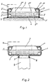
- the swivel bearing pot 1 consists of the comparatively thick-walled mounting plate 1V forming its bottom and the pot wall 1 VII, which is firmly connected therewith by the weld seam 10 and is initially again cylindrical.
- the latter thus consists of a simple tube section which can be welded onto the mounting plate 1 VI provided with screw mounting holes 11 or can also be riveted if necessary.
- the bearing balls of the rims 3 ', 3 and the swivel bearing plate 2 are inserted into the swivel bearing pot 1 in the upwardly open position shown in FIG.
- the container wall 1 VII is flanged at the upper end, that is, the flanged edge 1 "
- the flanging of the rim of the pot wall can be carried out in such a way that an optimal bearing play is created.
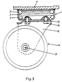
- FIG. 5 shows a swivel castor attached to a swivel bearing pot 1, the fork 12 of which carries the roller wheel 14 which can be rotated about the axis 13 and is fastened to the swivel bearing plate 2 by means of screws 16 penetrating its back 15.
Landscapes
- Engineering & Computer Science (AREA)
- General Engineering & Computer Science (AREA)
- Mechanical Engineering (AREA)
- Rolling Contact Bearings (AREA)
Applications Claiming Priority (2)
| Application Number | Priority Date | Filing Date | Title |
|---|---|---|---|
| DE3341063 | 1983-11-12 | ||
| DE19833341063 DE3341063A1 (de) | 1983-11-12 | 1983-11-12 | Verfahren zum herstellen von lenkrollen-schwenklagern und danach hergestelltes schwenklager |
Publications (2)
| Publication Number | Publication Date |
|---|---|
| EP0163671A1 EP0163671A1 (de) | 1985-12-11 |
| EP0163671B1 true EP0163671B1 (de) | 1989-08-02 |
Family
ID=6214227
Family Applications (1)
| Application Number | Title | Priority Date | Filing Date |
|---|---|---|---|
| EP84904099A Expired EP0163671B1 (de) | 1983-11-12 | 1984-11-08 | Verfahren zum herstellen von lenkrollen-schwenklagern und danach hergestelltes schwenklager |
Country Status (4)
| Country | Link |
|---|---|
| US (1) | US4620342A (enExample) |
| EP (1) | EP0163671B1 (enExample) |
| DE (1) | DE3341063A1 (enExample) |
| WO (1) | WO1985002151A1 (enExample) |
Families Citing this family (13)
| Publication number | Priority date | Publication date | Assignee | Title |
|---|---|---|---|---|
| US4887209A (en) * | 1986-11-11 | 1989-12-12 | Sharp Kabushiki Kaisha | Electronic cash register system |
| US4777697A (en) * | 1987-01-15 | 1988-10-18 | Berndt Lon G | Caster wheel mount apparatus with separate load carrying and swivel ball bearings |
| US5185695A (en) * | 1988-07-14 | 1993-02-09 | Pruchnicki Michael A | Method and system for handling discount coupons by using centrally stored manufacturer coupons in place of paper coupons |
| DE9012529U1 (de) * | 1990-09-01 | 1990-11-22 | Haco-Rollen-Vertrieb GmbH & Co KG, 5632 Wermelskirchen | Lenkrolle |
| US5390393A (en) * | 1993-01-22 | 1995-02-21 | Metro Industries, Inc. | Caster with a fouling-resistant bearing cup feature |
| USD349043S (en) | 1993-01-28 | 1994-07-26 | Metro Industries, Inc. | Caster |
| US5809612A (en) * | 1996-01-02 | 1998-09-22 | Teftec Corporation | Anti-Shimmy caster wheel Mounting |
| US5775819A (en) * | 1996-03-14 | 1998-07-07 | Virginia Industries, Inc. | Roller bearing assembly and method for making the same |
| CA2179802C (en) * | 1996-06-24 | 2000-09-12 | William Ross Shouldice | Heavy duty double-ball pinless caster, and method of manufacture thereof |
| KR200183590Y1 (ko) * | 1999-12-23 | 2000-05-15 | 조현덕 | 운반구용 캐스트 베어링 |
| GB0224644D0 (en) * | 2002-10-23 | 2002-12-04 | Urquhart Dykes & Lord | A castor |
| CA2416170A1 (en) * | 2003-01-13 | 2004-07-13 | Algood Casters Limited | Kingpin-free caster assembly |
| US7284299B2 (en) * | 2005-03-08 | 2007-10-23 | Rubbermaid Commercial Products Llp | Caster |
Family Cites Families (15)
| Publication number | Priority date | Publication date | Assignee | Title |
|---|---|---|---|---|
| US1403367A (en) * | 1920-02-24 | 1922-01-10 | Frank S Vander Bogart | Ball bearing |
| US1421647A (en) * | 1921-10-11 | 1922-07-04 | Jean F Wolfs | Caster |
| US1829862A (en) * | 1926-06-11 | 1931-11-03 | Colson Company | Caster |
| US1743255A (en) * | 1927-03-23 | 1930-01-14 | Lambert H Vervoort | Roller construction |
| US1821642A (en) * | 1929-09-16 | 1931-09-01 | Colson Company | Caster |
| GB366664A (en) * | 1930-12-19 | 1932-02-11 | Norman Albert Davies | Improvements in castors |
| CH245287A (de) * | 1944-02-24 | 1946-10-31 | Berger Karl | Einrichtung zur linearen Zeitablenkung von Kathodenstrahlen. |
| CH245267A (de) * | 1945-03-28 | 1946-10-31 | M J Purtschert & Co Ag | Um einen vertikalen Zapfen sich einstellende Laufrolle. |
| US3428378A (en) * | 1966-11-02 | 1969-02-18 | Mico Corp Ltd Di | Miniature ball bearing |
| NO136572C (no) * | 1969-03-11 | 1977-09-28 | Lyckeaborgs Bruk Ab | Lenkehjulsanordning. |
| DE7142834U (de) * | 1971-11-12 | 1972-02-17 | Haurand H Gmbh | Lagerfuß für eine Lenkrolle |
| DE2217520A1 (de) * | 1972-04-12 | 1973-11-08 | Happe & Co | Lenkrolle mit schwenklager |
| FR2252225A1 (en) * | 1973-11-28 | 1975-06-20 | Skf Ind Trading & Dev | Steerable roller wheel for furniture - has radial guide pivot projecting into boss on needle roller bearing guide |
| US4398329A (en) * | 1981-07-13 | 1983-08-16 | Virginia Industries, Inc. | Roller skate bearing |
| DE8228224U1 (de) * | 1982-10-08 | 1983-01-13 | Haco-Rollen-Vertrieb GmbH & Co KG, 5632 Wermelskirchen | Lenkrolle |
-
1983
- 1983-11-12 DE DE19833341063 patent/DE3341063A1/de active Granted
-
1984
- 1984-11-08 WO PCT/DE1984/000236 patent/WO1985002151A1/de not_active Ceased
- 1984-11-08 US US06/760,733 patent/US4620342A/en not_active Expired - Fee Related
- 1984-11-08 EP EP84904099A patent/EP0163671B1/de not_active Expired
Also Published As
| Publication number | Publication date |
|---|---|
| WO1985002151A1 (en) | 1985-05-23 |
| US4620342A (en) | 1986-11-04 |
| DE3341063A1 (de) | 1985-05-30 |
| DE3341063C2 (enExample) | 1987-09-24 |
| EP0163671A1 (de) | 1985-12-11 |
Similar Documents
| Publication | Publication Date | Title |
|---|---|---|
| EP0163671B1 (de) | Verfahren zum herstellen von lenkrollen-schwenklagern und danach hergestelltes schwenklager | |
| DE10060638B4 (de) | Radlagereinheit | |
| DE2828159A1 (de) | Einreihiges kegelrollenlager | |
| DE930992C (de) | Zwischenstueck zur loesbaren Befestigung eines Zubehoerteiles fuer Funkgeraete | |
| DE60038092T2 (de) | Rollenträger für Rad und Herstellungsverfahren | |
| DE69932849T2 (de) | Wälzlager | |
| DE4102471A1 (de) | Laufrollen | |
| DE3048922A1 (de) | Anschluss einer turasnabe an dem fahrgetriebe eines kettenfahrzeuges | |
| DE102009055754A1 (de) | Kegelrollenlager und Verfahren zur Montage des Kegelrollenlagers | |
| DE7122297U (de) | Als baueinheit ausgebildetes schwenkrad | |
| DE2512843B2 (de) | Verfahren zur Herstellung einer Tragrolle für Transportbänder oder Rollenbahnen | |
| DE2543211C2 (de) | Lenkrolle für von Hand bewegte Fahrzeuge insbesondere für Einkaufswagen | |
| DE19740897A1 (de) | Vorrichtung zum Befestigen einer Möbelrolle | |
| DE10229931A1 (de) | Laufrolle für Einkaufs- und Transportwagen | |
| DE1956836A1 (de) | Waelzlageranordnung und Verfahren zu dessen Herstellung | |
| DE3412169C1 (de) | Spannrolleneinheit | |
| DE7142834U (de) | Lagerfuß für eine Lenkrolle | |
| DE2010844A1 (de) | Lenkrollenvorrichtung | |
| DE1037871B (de) | Lenkkranz, insbesondere fuer Anhaenger- oder Gespannfahrzeuge | |
| DE2406042A1 (de) | Waelzlager | |
| DE2607629C3 (de) | Wagenheber mit Standsäule und an dieser verstellbar angeordnetem Tragarm | |
| EP0473997B1 (de) | Lenkrolle | |
| EP0682894B1 (de) | Laufrollen-Lagerung an Rollen-Ausziehführungen | |
| EP0440068A1 (de) | Lenkrolle | |
| DE2420987C2 (de) | Verfahren zur Montage einer axial wirkenden, festen Anschlaghülse für Lager von Walzen für Förderbandanlagen auf der Welle der Walze und Walze für Förderbandanlagen |
Legal Events
| Date | Code | Title | Description |
|---|---|---|---|
| PUAI | Public reference made under article 153(3) epc to a published international application that has entered the european phase |
Free format text: ORIGINAL CODE: 0009012 |
|
| 17P | Request for examination filed |
Effective date: 19850627 |
|
| AK | Designated contracting states |
Designated state(s): FR NL SE |
|
| 17Q | First examination report despatched |
Effective date: 19860903 |
|
| D17Q | First examination report despatched (deleted) | ||
| GRAA | (expected) grant |
Free format text: ORIGINAL CODE: 0009210 |
|
| AK | Designated contracting states |
Kind code of ref document: B1 Designated state(s): FR NL SE |
|
| ET | Fr: translation filed | ||
| PLBE | No opposition filed within time limit |
Free format text: ORIGINAL CODE: 0009261 |
|
| STAA | Information on the status of an ep patent application or granted ep patent |
Free format text: STATUS: NO OPPOSITION FILED WITHIN TIME LIMIT |
|
| 26N | No opposition filed | ||
| PGFP | Annual fee paid to national office [announced via postgrant information from national office to epo] |
Ref country code: SE Payment date: 19931008 Year of fee payment: 10 |
|
| PG25 | Lapsed in a contracting state [announced via postgrant information from national office to epo] |
Ref country code: SE Effective date: 19941109 |
|
| EAL | Se: european patent in force in sweden |
Ref document number: 84904099.3 |
|
| EUG | Se: european patent has lapsed |
Ref document number: 84904099.3 |
|
| PGFP | Annual fee paid to national office [announced via postgrant information from national office to epo] |
Ref country code: NL Payment date: 20000125 Year of fee payment: 16 |
|
| PGFP | Annual fee paid to national office [announced via postgrant information from national office to epo] |
Ref country code: FR Payment date: 20000131 Year of fee payment: 16 |
|
| PG25 | Lapsed in a contracting state [announced via postgrant information from national office to epo] |
Ref country code: NL Free format text: LAPSE BECAUSE OF NON-PAYMENT OF DUE FEES Effective date: 20010601 |
|
| PG25 | Lapsed in a contracting state [announced via postgrant information from national office to epo] |
Ref country code: FR Free format text: LAPSE BECAUSE OF NON-PAYMENT OF DUE FEES Effective date: 20010731 |
|
| NLV4 | Nl: lapsed or anulled due to non-payment of the annual fee |
Effective date: 20010601 |
|
| REG | Reference to a national code |
Ref country code: FR Ref legal event code: ST |
|
| APAH | Appeal reference modified |
Free format text: ORIGINAL CODE: EPIDOSCREFNO |