EP0161884A2 - Klemmeinrichtung um darin Elemente zu halten - Google Patents
Klemmeinrichtung um darin Elemente zu halten Download PDFInfo
- Publication number
- EP0161884A2 EP0161884A2 EP85303170A EP85303170A EP0161884A2 EP 0161884 A2 EP0161884 A2 EP 0161884A2 EP 85303170 A EP85303170 A EP 85303170A EP 85303170 A EP85303170 A EP 85303170A EP 0161884 A2 EP0161884 A2 EP 0161884A2
- Authority
- EP
- European Patent Office
- Prior art keywords
- socket
- base
- resilient member
- receive
- wall
- Prior art date
- Legal status (The legal status is an assumption and is not a legal conclusion. Google has not performed a legal analysis and makes no representation as to the accuracy of the status listed.)
- Granted
Links
Images


Classifications
-
- B—PERFORMING OPERATIONS; TRANSPORTING
- B42—BOOKBINDING; ALBUMS; FILES; SPECIAL PRINTED MATTER
- B42F—SHEETS TEMPORARILY ATTACHED TOGETHER; FILING APPLIANCES; FILE CARDS; INDEXING
- B42F15/00—Suspended filing appliances
- B42F15/06—Suspended filing appliances for hanging large drawings or the like
- B42F15/066—Suspended filing appliances for hanging large drawings or the like for hanging a single drawing, e.g. with self-locking means
-
- A—HUMAN NECESSITIES
- A47—FURNITURE; DOMESTIC ARTICLES OR APPLIANCES; COFFEE MILLS; SPICE MILLS; SUCTION CLEANERS IN GENERAL
- A47G—HOUSEHOLD OR TABLE EQUIPMENT
- A47G1/00—Mirrors; Picture frames or the like, e.g. provided with heating, lighting or ventilating means
- A47G1/16—Devices for hanging or supporting pictures, mirrors, or the like
- A47G1/20—Picture hooks; X-hooks
- A47G1/21—Picture hooks; X-hooks with clamping action
Definitions
- This invention relates to gripping devices for receiving and holding one or more elements or components therein.
- the device may be used in the office, workshop or home and, as such, may be utilised to hold single or multiple elements or components including tools, domestic utensils such as kitchen implements, office equipment, sheet material such as paper, card, plastics, textile material for screens or curtaining and so on or as a glazing grip for glass or plastics sheeting.
- This invention provides a device for holding an element or component therein comprising an elongate socket to receive a part of an element or component and an elongate resilient member (which may be a separate component or may be formed integrally with the socket) extending lengthwise of the socket and being mounted on one side against thereof to the other side of the socket to receive and trap said marginal part against said side of the socket.
- an elongate resilient member which may be a separate component or may be formed integrally with the socket
- the elongate resilient member permits a number of differently sized elements or components to be held in the socket at spaced locations along the socket as well as uniform thickness elements such as sheets of paper or card.
- the resilient member may comprise a base mounted on one side of the socket and an upstanding resilient leg extending from the base to bear on the other side of the socket and, more specifically the base of the resilient member may be so mounted in the socket that the leg is bowed by engagement with said side of the socket to trap said marginal part of an element agaist the one side of the socket.
- the leg may be L-shaped in cross-section, the base of the L forming the base of the resilient member and the upright of the L forming the resilient leg of the member.
- the base of the resilient member may lie against the one side of the socket and means are provided in the socket for holding the base against said one side.
- the means for holding the base of the resilient member against said one side of the socket may comprise an intermediate wall extending partway across the socket parallel to said other side to receive the base member between the wall and said one side of the socket and an upstanding abutment on said one side of the socket at the open end thereof.
- the socket may comprise a base and an upstanding pair of convergent side walls with a gap between the edges of the side walls remote from the base to receive the marginal part of the component to be gripped, the inner face of one of the side walls forming said one side of the socket and the inner face of the other side wall forming the other side of the socket.
- said one face of the socket may have a self-adhesive strip or strips extending lengthwise of the socket to adhere the socket to a further surface or may have one or more key hole slots to receive appropriate headed fixings for mounting the socket.
- a board may be provided having an elongate recess to receive and hold the socket of the gripping device.
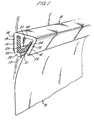
- FIG. 1 of the drawings there is shown a sheet of paper or card 10 which is suspended generally vertically along its upper edge part 11 by an elongate gripping device indicated at 12.
- the grip comprises a rigid plastics (e.g. PVC) or aluminium extruded socket indicated generally at 13 comprising a horizontally extending base wall 14 having along one edge a vertically downwardly extending side wall 15 and along the opposite edge a downwardly angled side wall 16 which converges with the side wall 15 to leave a gap indicated at 17 between the lower edges thereof to receive the upper edge 11 of a sheet of paper or card as described below.
- a rigid plastics e.g. PVC
- aluminium extruded socket indicated generally at 13 comprising a horizontally extending base wall 14 having along one edge a vertically downwardly extending side wall 15 and along the opposite edge a downwardly angled side wall 16 which converges with the side wall 15 to leave a gap indicated at 17 between the lower edges thereof to receive the upper edge 11 of a sheet of paper or card as described below.
- the outer face 18 of the side wall 15 of the socket has a double sided adhesive strip or pad 19 thereon to adhere the side wall to a face of a wall, board or other support surface on which the paper grip is to be mounted.
- the lower edge of the side wall 15 is formed with a laterally extending abutment 20 extending partway across the socket opening 17.
- the base 14 of the socket is formed with a downwardly extending intermediate partition wall 21 parallel to and spaced from the side wall 15.
- An L-shaped flexible extrusion or neoprene rubber or other resilient plastics 22 is mounted in the socket with the base 23 of the resilient extrusion trapped against the side wall 15 by the partition wall 21 and abutment 20.
- the upright 24 of the L extends across the socket and is "bowed” to bear against the inside face of the angled side wall 16 so that the leg is resiliently biased against the side wall.
- the lower edge of the side wall 16 of the socket is chamfered inwardly of the socket as indicated at 25 to form a tapering throat to receive the upper edge of a sheet of paper or card 10 fed through the opening into the socket to guide the edge of the sheet between the resilient leg 24 of the extrusion 22 and the side wall 16 of the socket.
- the sheet of paper or card forces the leg 24 of the resilient extrusion away from the side wall 16 as the sheet is pressed upwardly into the socket and the resilience in the leg traps and holds the upper edge of the sheet against the side wall 16.
- both the socket and resilient member of the paper grip are formed by extrusion and can readily be cut to any suitable length required to suit the particular use to which the grip is to be put.
- a long piece of socket may be provided to receive the whole of an edge of a sheet of paper or card, or short lengths of socket may be mounted at spaced locations to receive the edge of a sheet of paper at different locations along the edge.
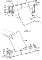
- FIG. 2 shows a virtually identical socket 12 in which the adhesive strip 19 is omitted and the socket is embodied in a moulded plastics (e.g. vacuum formed from ABS or glass reinforced plastics) backing board 26 formed with a V-shaped recess 27 to receive the base and side 15 of the socket with the opening 17 of the socket facing downwardly over the surface of the board.
- the board has a moulded rigde 28 against which the lower edge of the side wall 15 of the socket bears to hold the socket in the recess so that the socket is a "snap fit" in the recess.
- Glazing may also be provided for the board to protect any sheet of paper or card mounted on the board.
- the extruded socket 13 in the embodiment of Figure 3 is an inverted parallel sided U-shaped channel having a base 40, a rear wall 15 and a front wall 16.
- the rear wall 15 projects downwardly somewhat further than the front wall 16 and the projecting part of the rear wall is formed with an integral obliquely extending channel 30 which faces generally across the mouth of and into the socket.
- a resilient flap 31 has an integral base part 31a which seats in the channel 30 and the flap extends across the mouth of the socket and along the inner side of the front wall 16 almost to the base 14 of the socket.
- the channel 30 is so angled that the flap is held in curved or "bowed” form to bear resiliently against the inner side of the front wall to trap a component or element such as the head 11 of a sheet of paper or card 10 against the inside of the front wall to support the piece of paper or card (or other component) suspended from the socket.
- the outer side of the rear wall 15 of the socket may have a doubled sided adhesive pads 32 bonded thereto to adhere the socket to the surface of a notice board or suitable backing board.
- the rear wall 15 of the socket has a downwardly directed extension 15a to increase the depth of the wall and thereby provide a deeper base for deeper adhesive pads to provide a more stable mounting for the socket.
- the extension 15a could be extended further to form a backboard integral with the gripping device so that a sheet of paper held in the gripping device can rest against the backboard for writing on, the device and backboard together thus forming a clipboard.
- the socket 13 forms a male projection slidably engaged in a corresponding recess in a backboard or other support.
- the rear wall of the socket is provided with keyhole slots 15b (shown in dotted outline) spaced along the wall to receive spaced headed pins (not shown) projecting from a surface on which the device is to be mounted.
- the socket is built into a backing board.
- the backing board 35 has an integral recess 36 in which socket 12 is mounted, and a bevelled corner 37 is formed between the lower side of the recess and lower part of the board 35 to provide a clear entry for inserting the head of a sheet of paper in the socket.
- the socket is otherwise identical to that described with reference to Figure 3.
- the socket may be bonded into the recess or the recess may be formed so that the walls spring apart to receive the socket and the natural resilience of the backing board clamps the socket in the recess.
- socket and resilient flap may be formed as a joint extrusion of suitable plastics materials rather than as separate components as illustrated.
- the stiffness of the resilient member may be varied to suit the particular application of the gripping device.
- the embodiments illustrate a smooth surface on the resilient member, the surface could be formed with ridges, or a rough surface to enhance gripping of a component or element to be located in the device.
- the gripping devices described above are intended for use in the workshop, office or home and may be employed for holding single or multiple implements or utensils such as a set of tools, other small articles or components as well as sheet paper, card or photographic prints or negatives and the length and dimensions of the section are sized accordingly.
- a suitable length or lengths of the gripping device can also be utilised to support sheets of textile or other like material to serve as screening or curtaining.
- Figure 5 shows the gripping device of Figure 3 in use and holding a multiplicity of different elements including a sheet of paper, a ticket and key at spaced locations along the socket.
- the gripping device may also be used with the socket open upwardly instead of downwardly as illustrated in Figure 6. In this mode the device can be used on a desk or work top to hold components.
- the extruded section may also be joined or formed integral with another device such as a date/time display device or other similar device.
- the dimensions of the socket of the gripping device are varied to suit its intended purpose and in particular the opening of the socket, the length of the socket and the cross-section of the socket are varied according to the application.
- a further application of the gripping device is as a glazing bar for glass or plastics panes or sheets:
- the resilient member both holds the glass or plastics pane in the socket and prevents ingress of moisture.
- Such glazing bars could form an integral part of a glazed structure such as a greenhouse, cold frame or the like.
Landscapes
- Supports Or Holders For Household Use (AREA)
- Sheet Holders (AREA)
- Feeding Of Articles By Means Other Than Belts Or Rollers (AREA)
Priority Applications (1)
| Application Number | Priority Date | Filing Date | Title |
|---|---|---|---|
| AT85303170T ATE55948T1 (de) | 1984-05-04 | 1985-05-03 | Klemmeinrichtung um darin elemente zu halten. |
Applications Claiming Priority (4)
| Application Number | Priority Date | Filing Date | Title |
|---|---|---|---|
| GB848411545A GB8411545D0 (en) | 1984-05-04 | 1984-05-04 | Sheet grips |
| GB8411545 | 1984-05-04 | ||
| GB8501662 | 1985-01-23 | ||
| GB08501662A GB2158141B (en) | 1984-05-04 | 1985-01-23 | Gripping devices for holding elements suspended therefrom |
Publications (3)
| Publication Number | Publication Date |
|---|---|
| EP0161884A2 true EP0161884A2 (de) | 1985-11-21 |
| EP0161884A3 EP0161884A3 (en) | 1987-09-30 |
| EP0161884B1 EP0161884B1 (de) | 1990-08-29 |
Family
ID=26287702
Family Applications (1)
| Application Number | Title | Priority Date | Filing Date |
|---|---|---|---|
| EP85303170A Expired - Lifetime EP0161884B1 (de) | 1984-05-04 | 1985-05-03 | Klemmeinrichtung um darin Elemente zu halten |
Country Status (6)
| Country | Link |
|---|---|
| US (1) | US4773545A (de) |
| EP (1) | EP0161884B1 (de) |
| JP (1) | JPS6122996A (de) |
| CA (1) | CA1270367A (de) |
| DE (1) | DE3579359D1 (de) |
| ES (1) | ES286492Y (de) |
Cited By (1)
| Publication number | Priority date | Publication date | Assignee | Title |
|---|---|---|---|---|
| AT398892B (de) * | 1988-09-03 | 1995-02-27 | Tegtmeier Metallbau | Klemmvorrichtung für folien |
Families Citing this family (30)
| Publication number | Priority date | Publication date | Assignee | Title |
|---|---|---|---|---|
| US4899974A (en) * | 1989-05-18 | 1990-02-13 | Popco Inc. | Display clip structure |
| USD320521S (en) | 1989-08-14 | 1991-10-08 | August Baur | Hanger for wall quilts |
| USD326027S (en) | 1989-08-14 | 1992-05-12 | Grip-A-Strip, Inc. | Poster wall hanger assembly or the like |
| US5048698A (en) * | 1990-06-12 | 1991-09-17 | Westinghouse Electric Corp. | Office accessory mounting rail |
| DE4429480C1 (de) * | 1994-08-19 | 1995-07-06 | Tele Plast Bleyer Und Gaertner | Vorrichtung zum Halten eines Papierblattes |
| US6286800B1 (en) * | 1994-12-27 | 2001-09-11 | Tristan P. Junius | Note paper holder |
| US5738228A (en) * | 1996-05-24 | 1998-04-14 | Bittinger; Andrew H. | Object holder |
| US6439399B1 (en) * | 1999-09-22 | 2002-08-27 | Hallmark Cards, Incorporated | Molded display rack with snap-in retainer and hinged mold insert tool |
| US6158597A (en) * | 1999-11-05 | 2000-12-12 | At-A-Glance, Inc. | Hangable calendar assembly |
| US6257422B1 (en) | 1999-11-29 | 2001-07-10 | Jaime Rios | Article holder |
| US6453518B1 (en) | 2000-08-04 | 2002-09-24 | The Mead Corporation | Holder for sheet material |
| JP2004037493A (ja) * | 2002-06-28 | 2004-02-05 | Kokuyo Co Ltd | カード取付具 |
| US20040163295A1 (en) * | 2003-02-24 | 2004-08-26 | Fontana Jill N. | Apparatus to display decorative art and method thereof |
| US20050012015A1 (en) * | 2003-07-09 | 2005-01-20 | Pitcher David E. | Flexable roller arrangement |
| US20060108493A1 (en) * | 2004-11-22 | 2006-05-25 | Paris Dean S | Holder for sheet material |
| US20070113452A1 (en) * | 2005-11-23 | 2007-05-24 | Pollack Ronald M | Note holder and method of making same |
| US20070199222A1 (en) * | 2006-02-24 | 2007-08-30 | Turner William F R | Display support device |
| US20090320344A1 (en) * | 2006-04-13 | 2009-12-31 | Southern Imperial, Inc. | Price channel extrusion with sign holding grip |
| US20070240349A1 (en) * | 2006-04-13 | 2007-10-18 | Southern Imperial, Inc. | Price channel extrusion with sign holding grip |
| JP4813243B2 (ja) * | 2006-04-24 | 2011-11-09 | 株式会社キングジム | 書類用ホルダ |
| USD602090S1 (en) | 2008-06-05 | 2009-10-13 | Staples The Office Superstore, Llc | Clipboard |
| USD656546S1 (en) | 2008-06-05 | 2012-03-27 | Staples The Office Superstore, Llc | Clipboard |
| USD601631S1 (en) | 2008-06-05 | 2009-10-06 | Staples The Office Superstore, Llc | Clipboard |
| US20100001164A1 (en) * | 2008-07-02 | 2010-01-07 | Popco, Inc. | Poster clasp |
| USD680754S1 (en) | 2009-06-26 | 2013-04-30 | Stuart C. W. Wear | Poster clasp |
| TW201437109A (zh) * | 2012-12-10 | 2014-10-01 | 3M Innovative Properties Co | 具有彈性固定構件之整理盒 |
| TWI632534B (zh) * | 2016-08-26 | 2018-08-11 | 佳世達科技股份有限公司 | 顯示裝置 |
| US10492596B2 (en) * | 2017-02-06 | 2019-12-03 | Audrey Pegues | Brush organizer system |
| US10803777B1 (en) * | 2018-04-23 | 2020-10-13 | Scott C. Moody | Apparatus and methods for mounting a poster |
| AU2024226143A1 (en) * | 2023-02-25 | 2025-10-02 | Kappa Agtech, Llc | Devices and methods for growing crops with non-fibrous, non-porous and non-consumable substrate |
Family Cites Families (14)
| Publication number | Priority date | Publication date | Assignee | Title |
|---|---|---|---|---|
| US793162A (en) * | 1904-09-03 | 1905-06-27 | Godfrey P Schmidt | Holder for sample-exhibitors. |
| US2530821A (en) * | 1945-08-20 | 1950-11-21 | Howard Hunt Pen Co C | Bulletin sheet holder and support |
| US2783880A (en) * | 1953-10-08 | 1957-03-05 | Chadbourn Sales Corp | Hosiery display device |
| US2785919A (en) * | 1955-03-08 | 1957-03-19 | Bobchet Ind Inc | Holding device |
| DE1191942B (de) * | 1955-08-24 | 1965-04-29 | Paul Nievergelt | Klemmleiste zum Aufhaengen flaechenhafter Gegenstaende, wie Zeichnungen, Schriftstuecke u. dgl. |
| US2918244A (en) * | 1959-04-06 | 1959-12-22 | Bestile Mfg Company | Clip |
| US3063569A (en) * | 1960-12-19 | 1962-11-13 | Eastern Rotorcraft Corp | Friction type holder device |
| FR1466737A (fr) * | 1966-01-31 | 1967-01-20 | Elderen S Metaalfab Brabantia | Porte-serviette |
| GB1127357A (en) * | 1966-08-27 | 1968-09-18 | Andrew Textile Developments Lt | Improvements in gripping devices for sheet material |
| US4010517A (en) * | 1974-09-12 | 1977-03-08 | Kapstad Odd B | Sheet support apparatus |
| US3938667A (en) * | 1974-09-19 | 1976-02-17 | Buckland Bonnie P | Combination tie rack |
| US3946877A (en) * | 1974-11-12 | 1976-03-30 | Virgil Rene Galicia | Clip-type holder for toothbrushes or the like |
| JPS5290071A (en) * | 1976-01-16 | 1977-07-28 | Mitsubishi Electric Corp | Valve unit |
| US4194635A (en) * | 1977-11-21 | 1980-03-25 | Agfa-Gevaert | X-ray film grip |
-
1985
- 1985-05-03 US US06/730,424 patent/US4773545A/en not_active Expired - Fee Related
- 1985-05-03 CA CA000480674A patent/CA1270367A/en not_active Expired - Fee Related
- 1985-05-03 DE DE8585303170T patent/DE3579359D1/de not_active Expired - Fee Related
- 1985-05-03 ES ES1985286492U patent/ES286492Y/es not_active Expired
- 1985-05-03 EP EP85303170A patent/EP0161884B1/de not_active Expired - Lifetime
- 1985-05-04 JP JP60095873A patent/JPS6122996A/ja active Pending
Cited By (1)
| Publication number | Priority date | Publication date | Assignee | Title |
|---|---|---|---|---|
| AT398892B (de) * | 1988-09-03 | 1995-02-27 | Tegtmeier Metallbau | Klemmvorrichtung für folien |
Also Published As
| Publication number | Publication date |
|---|---|
| DE3579359D1 (de) | 1990-10-04 |
| JPS6122996A (ja) | 1986-01-31 |
| ES286492U (es) | 1986-05-01 |
| EP0161884A3 (en) | 1987-09-30 |
| EP0161884B1 (de) | 1990-08-29 |
| CA1270367A (en) | 1990-06-19 |
| ES286492Y (es) | 1987-01-16 |
| US4773545A (en) | 1988-09-27 |
Similar Documents
| Publication | Publication Date | Title |
|---|---|---|
| EP0161884A2 (de) | Klemmeinrichtung um darin Elemente zu halten | |
| ATE252861T1 (de) | Haltevorrichtung | |
| US6257422B1 (en) | Article holder | |
| US5117598A (en) | Molding strips for mounting a flexible covering onto a support surface | |
| WO1996009788A1 (en) | Self-adjusting glass shelf label holder | |
| BG103716A (en) | Fastening device for a screening structure | |
| WO1994010884A1 (en) | Wall article hanging device | |
| US4641441A (en) | Frame retaining clip | |
| GB2249125A (en) | A holder for sheet material | |
| US7121030B2 (en) | Picture framing system | |
| US4974351A (en) | Hook for clamping together two panels for making picture holders or similar objects | |
| CA1208905A (en) | Fastening clips | |
| US5927031A (en) | Stabilizer frame for corner siding and method | |
| US5109619A (en) | Picture frame retainer | |
| GB2154778A (en) | Ticket holder | |
| US5735069A (en) | Frame assembly | |
| US4811926A (en) | Panel retaining apparatus | |
| US4261123A (en) | Sections for picture frames | |
| US3063666A (en) | Picture hanger | |
| GB2158141A (en) | Gripping devices for holding elements suspended therefrom | |
| US4837954A (en) | Transparent picture frame construction | |
| US2877879A (en) | Multi-purpose structure | |
| US3798815A (en) | Retaining device for picture frames | |
| CA1286108C (en) | Universal picture support assembly | |
| US6065236A (en) | Picture framing system |
Legal Events
| Date | Code | Title | Description |
|---|---|---|---|
| PUAI | Public reference made under article 153(3) epc to a published international application that has entered the european phase |
Free format text: ORIGINAL CODE: 0009012 |
|
| AK | Designated contracting states |
Designated state(s): AT BE CH DE FR GB IT LI LU NL SE |
|
| PUAL | Search report despatched |
Free format text: ORIGINAL CODE: 0009013 |
|
| AK | Designated contracting states |
Kind code of ref document: A3 Designated state(s): AT BE CH DE FR GB IT LI LU NL SE |
|
| 17P | Request for examination filed |
Effective date: 19880330 |
|
| 17Q | First examination report despatched |
Effective date: 19890524 |
|
| GRAA | (expected) grant |
Free format text: ORIGINAL CODE: 0009210 |
|
| AK | Designated contracting states |
Kind code of ref document: B1 Designated state(s): AT BE CH DE FR GB IT LI LU NL SE |
|
| PG25 | Lapsed in a contracting state [announced via postgrant information from national office to epo] |
Ref country code: SE Free format text: THE PATENT HAS BEEN ANNULLED BY A DECISION OF A NATIONAL AUTHORITY Effective date: 19900829 Ref country code: LI Effective date: 19900829 Ref country code: CH Effective date: 19900829 Ref country code: AT Effective date: 19900829 |
|
| REF | Corresponds to: |
Ref document number: 55948 Country of ref document: AT Date of ref document: 19900915 Kind code of ref document: T |
|
| ITF | It: translation for a ep patent filed | ||
| REF | Corresponds to: |
Ref document number: 3579359 Country of ref document: DE Date of ref document: 19901004 |
|
| ET | Fr: translation filed | ||
| REG | Reference to a national code |
Ref country code: CH Ref legal event code: PL |
|
| PG25 | Lapsed in a contracting state [announced via postgrant information from national office to epo] |
Ref country code: LU Free format text: LAPSE BECAUSE OF NON-PAYMENT OF DUE FEES Effective date: 19910531 |
|
| PLBE | No opposition filed within time limit |
Free format text: ORIGINAL CODE: 0009261 |
|
| 26N | No opposition filed | ||
| PGFP | Annual fee paid to national office [announced via postgrant information from national office to epo] |
Ref country code: BE Payment date: 19920507 Year of fee payment: 8 |
|
| PGFP | Annual fee paid to national office [announced via postgrant information from national office to epo] |
Ref country code: FR Payment date: 19920515 Year of fee payment: 8 |
|
| ITTA | It: last paid annual fee | ||
| PGFP | Annual fee paid to national office [announced via postgrant information from national office to epo] |
Ref country code: NL Payment date: 19920531 Year of fee payment: 8 |
|
| PGFP | Annual fee paid to national office [announced via postgrant information from national office to epo] |
Ref country code: DE Payment date: 19920722 Year of fee payment: 8 |
|
| PG25 | Lapsed in a contracting state [announced via postgrant information from national office to epo] |
Ref country code: BE Effective date: 19930531 |
|
| BERE | Be: lapsed |
Owner name: INOVENTORS LTD Effective date: 19930531 |
|
| PG25 | Lapsed in a contracting state [announced via postgrant information from national office to epo] |
Ref country code: NL Effective date: 19931201 |
|
| NLV4 | Nl: lapsed or anulled due to non-payment of the annual fee | ||
| PG25 | Lapsed in a contracting state [announced via postgrant information from national office to epo] |
Ref country code: FR Effective date: 19940131 |
|
| PG25 | Lapsed in a contracting state [announced via postgrant information from national office to epo] |
Ref country code: DE Effective date: 19940201 |
|
| REG | Reference to a national code |
Ref country code: FR Ref legal event code: ST |
|
| REG | Reference to a national code |
Ref country code: GB Ref legal event code: IF02 |
|
| PGFP | Annual fee paid to national office [announced via postgrant information from national office to epo] |
Ref country code: GB Payment date: 20030502 Year of fee payment: 19 |
|
| PG25 | Lapsed in a contracting state [announced via postgrant information from national office to epo] |
Ref country code: GB Free format text: LAPSE BECAUSE OF NON-PAYMENT OF DUE FEES Effective date: 20040503 |
|
| GBPC | Gb: european patent ceased through non-payment of renewal fee |
Effective date: 20040503 |