EP0161861B1 - Procédé et dispositif pour le recuit continu de rubans d'acier laminés à froid - Google Patents
Procédé et dispositif pour le recuit continu de rubans d'acier laminés à froid Download PDFInfo
- Publication number
- EP0161861B1 EP0161861B1 EP85303046A EP85303046A EP0161861B1 EP 0161861 B1 EP0161861 B1 EP 0161861B1 EP 85303046 A EP85303046 A EP 85303046A EP 85303046 A EP85303046 A EP 85303046A EP 0161861 B1 EP0161861 B1 EP 0161861B1
- Authority
- EP
- European Patent Office
- Prior art keywords
- high temperature
- zone
- region
- heating
- strip
- Prior art date
- Legal status (The legal status is an assumption and is not a legal conclusion. Google has not performed a legal analysis and makes no representation as to the accuracy of the status listed.)
- Expired
Links
Images


Classifications
-
- C—CHEMISTRY; METALLURGY
- C21—METALLURGY OF IRON
- C21D—MODIFYING THE PHYSICAL STRUCTURE OF FERROUS METALS; GENERAL DEVICES FOR HEAT TREATMENT OF FERROUS OR NON-FERROUS METALS OR ALLOYS; MAKING METAL MALLEABLE, e.g. BY DECARBURISATION OR TEMPERING
- C21D9/00—Heat treatment, e.g. annealing, hardening, quenching or tempering, adapted for particular articles; Furnaces therefor
- C21D9/52—Heat treatment, e.g. annealing, hardening, quenching or tempering, adapted for particular articles; Furnaces therefor for wires; for strips ; for rods of unlimited length
- C21D9/54—Furnaces for treating strips or wire
- C21D9/56—Continuous furnaces for strip or wire
Definitions
- This invention relates to a continuous annealing method and a continuous annealing apparatus for cold rolled steel strips, and more particularly to a method and an apparatus for continuously annealing steel strips in a manner effectively preventing meandering and heat buckling of the strips during heat-treatment.
- continuous annealing furnaces for cold rolled steel strips are of the vertical type for cost reasons and in view of the available space for the furnace.
- a number of hearth rolls 1 are arranged in the upper and lower portions of the furnace 2.
- a steel strip S is trained around these upper and lower hearth rolls alternately upward and downward in a serpentine path during which the strip S is subjected to the predetermined heat-treatment required to obtain the desired material characteristics.
- crown or tapered rolls l' or 1" have usually been used as hearth rolls, which rolls include tapered ends as shown in Figures 2a and 2b of the accompanying drawings, which cause centering forces to urge the steel strips towards the maximum diameter portions of the rolls at their centre and thereby prevent meandering of the strips.
- the centering force tends to exceed a certain level and causes buckling of the strips in their width direction resulting in defects in the steel products called "heat buckling".
- Hearth rolls capable of changing their crowning or tapered amounts have been proposed to solve the above problems as disclosed in Japanese Laid-open Utility Model Application No. 55-172,359, Japanese Laid-open Patent Application No. 57-177,930 and Japanese Laid-open Patent Application No. 58-105,464.
- Such systems, thereof, are very expensive and also have a low response time.
- Steel strips having a carbon content of less than 0.1% are generally used for deep drawing.
- extremely low-carbon steels having a carbon content of the order of less than 0.005% have been used for materials for deep drawing.
- These cold rolled steel plates for deep drawing are to be annealed at temperatures higher than 800°C and are prone to heat buckling. Such a tendency is more acute in low-carbon steels as the carbon content becomes extremely low.
- FIG. 3 of the accompanying drawings schematically illustrates a hitherto used continuous annealing furnace suitable for continuous heat-treating blank materials for tin plates.
- This furnace includes a heating region 3, a soaking region 4, a slow cooling region 5 and a rapid cooling region 6, through which a steel strip S passes progressively-so as to be subjected to predetermined heat-treatment.
- Figures 4a and 4b of the accompanying drawing illustrates the frequencies at which meandering and heat buckling of steel strips annealed in the continuous annealing furnace shown in Figure 3 occur in relationship to the crowning amounts of the hearth rolls in the upstream and downstream halves of the heating region, the soaking region, and the slow and quick cooling regions.
- heat buckling tends to occur in the high temperature zones such as the downstream half of the heating region, the soaking region and the slow cooling region, while the meandering of the steel strips is restrained in these high temperature zones.
- FIG. 5 of the accompanying drawings schematically illustrates a hitherto used continuous annealing line including a continuous annealing furnace for steel strips to be deep drawn.
- a steel strip S is wound off at pay-off reels 7 and 7' and is subjected to pretreatment in a device located at the entry side, such as a welder or cleaning device, and thereafter is fed through a looper at the entry side and into the continuous annealing furnace 10.
- the steel strip S is subjected to predetermined heat-treatments while progressively passing through a preheating region 11, a heating region 12, a soaking region 13, a primary cooling region 14, a secondary cooling region 15, an overaging treating region 16 and a third cooling region 17, and is then fed through a looper 18 at the exit side and into a treating device 19 such as a shearer for after-treatment. Thereafter, the steel strip is wound up on tension reels 20 and 20'.
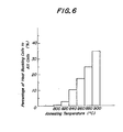
- Figure 6 of the accompanying drawings shows the rates or percentages of occurrence of heat buckling of steel strips to be deep drawn when subjected to heat-treatment in the continuous annealing furnace shown in Figure 5.
- the abscissa shows the heating temperatures of the strips and the ordinate shows the number of coils which exhibited heat buckling as a percentage of the number of all the treated coils.
- heat buckling does not occur at steel strip temperatures of lower than 780°C, but rapidly increases as the temperature becomes higher than 780°C.
- Figure 7 of the accompanying drawings illustrates heat buckling in the case of extremely low-carbon blank strips (0.2-0.3 mm thickness) for tin plates in the same manner as Figure 6.
- a method of continuously annealing a cold rolled steel strip which comprises successively conveying the strip through a heating zone, a high temperature zone and a cooling zone, wherein the strip follows a serpentine path upwardly and downwardly in the heating and cooling zones and follows a path in a single direction in the high temperature zone.
- an apparatus for continuously annealing a cold rolled steel strip which apparatus comprises a heating zone, a high temperature zone and a cooling zone through each of which the strip successively passes wherein the heating and cooling zones include hearth rolls to guide the strip alternately upwardly and downwardly along a serpentine path and wherein the high temperature zone is devoid of hearth rolls to guide the strip alternately upwardly and downwardly so that the path of the strip through the high temperature zone lies in a single direction.
- the steel strip In the high temperature zone, the steel strip is fed in a substantially horizontal or vertical direction, while in the remaining zones, the steel strip is fed alternately upwards and downwards along a serpentine path with the aid of a number of hearth rolls.
- the steel strip is heated in a low temperature heating region provided in the heating zone adjacent to and upstream of the high temperature zone, and is further heated and soaked in the high temperature heating zone.
- the high temperature zone also includes a primary cooling region where some cooling of the strip occurs and thereafter the steel s-zrip is further cooled in the cooling zone which is provided adjacent to and downstream of the high temperature zone and constitutes a secondary cooling region.
- the temperatures of the steel strip immediately before entering and immediately after leaving the high temperature zone are preferably controlled so that heat buckling does not occur.
- the temperatures should be kept lower than 780°C.
- the high temperature zone is in the form of a single furnace through which the steel strip passes only once in a single direction. It is in the high temperature zone where steel strips are prone to heat buckling and this is avoided in accordance with the present invention by guiding the strips in a single direction through this zone.
- the high temperature zone single furnace may be a horizontal or a vertical furnace.
- the high temperature zone single furnace forms therein a high temperature heating and soaking region for heating and soaking the steel strip at high temperature and a primary cooling region adjacent to and downstream of the soaking region for primarily cooling the steel strip.
- the high temperature single furnace is a horizontal furnace preferably located above a low temperature heating vertical furnace and a preheating vertical furnace or above a low temperature heating vertical furnace, a preheating vertical furnace, a secondary cooling vertical furnace, an overaging treating vertical furnace and a third cooling vertical furnace.
- This annealing apparatus comprises a heating zone including a preheating region 21 and a low temperature heating region 22 and a high temperature zone comprising a high temperature heating and soaking region 23.
- a primary cooling region 24 horizontally contiguous to the high temperature heating and soaking region 23 forms a part of the high temperature zone.
- the horizontal zone including regions 23 and 24 is formed by a single furnace located above the vertical furnaces constituting the preheating region 21 and the low temperature heating region 22.
- the annealing apparatus further comprises a cooling zone in the form of a secondary cooling region 25, an overageing treating region 26 and a third cooling region 27, each respectively consisting of vertical furnaces.
- the high temperature zone comprising heating and soaking regions 23 and the primary cooling region 24 are arranged in the horizontal single furnace which includes no hearth rolls.
- the steel strip can pass through these regions only once in a single direction.
- no hearth rolls are present in the high temperature zone to cause heat buckling of the steel strips.
- each zone other than the high temperature zone i.e. other than the heating and soaking regions 23 and the primary cooling region 24
- the steel strip is driven by hearth rolls alternately upwards and downwards ulong a serpentine path.
- a steel strip S is subjected to heat-treatment according to heat pattern A as shown in Figure 9 to obtain its predetermined material characteristics.
- the steel strip S is heated to a certain temperature in the heating zone comprising the preheating region 21 and the low temperature heating region 22, it is introduced into the high temperature heating and soaking regions 23 of the horizontal furnace arranged above the preheating and low temperature heating regions 21 and 22 so as to be subjected to a predetermined heat-treatment.
- the steel strip S is fed into the primary cooling region 24 so as to permit its temperature to fall to a predetermined temperature.
- the steel strip is then introduced into the cooling zone comprising the secondary cooling region 25, the overaging treating region 26, and the third cooling region 27 in the vertical furnaces to give the desired material characteristics to the strip.
- the temperature of the steel strip immediately before entering the high temperature heating and soaking region 23 and immediately after leaving the primary cooling region 24 is lower than 780°C in view of the results shown in Figure 6 in order to prevent heat buckling.
- Radiant tube type burners are preferably used for heating the low temperature heating region 22 and the high temperature heating and soaking region 23.
- the preheating region 21 is preferably heated directly by exhaust gases from the region 22 and 23 or by air which has been heat-exchanged with the exhaust gases from the regions 22 and 23.
- the primary, secondary and third cooling regions 24, 25 and 27 are preferably cooled by gas-jet cooling systems using a non-oxidizing atmosphere gas, or by a roll cooling system using cooling rolls contacting the steel strips or by a combination of roll cooling and gas-jet cooling systems.
- the overaging treatment region 26 is preferably heated by radiant heating using electric heaters or radiant tubes.
- Figure 10 illustrates another embodiment of continuous annealing apparatus according to the invention which is preferred for annealing cold rolled steel strips for deep drawing.
- annealing steel strips for deep drawing either of the apparatus shown in Figures 8 and 10 may be selected according to the heating speeds or the temperature of the steel strips in the proximity of the entrance to the horizontal furnace.
- FIG 11 illustrates a further preferred embodiment of continuous annealing apparatus according to the invention for cold rolled low-carbon steel strips of extremely low-carbon content for deep drawing.
- This apparatus is similar to that shown in Figure 10 with the exception that the cooling zone consists only of a vertical furnace on the downstream side forming secondary cooling zone 25'.
- steel strip S passes successively through preheating region 21, low temperature heating region 22 and high temperature heating and soaking regions 23 and is then rapidly cooled in primary cooling region 24 and the secondary cooling region 25' according to heat pattern B shown in Figure 9 so as to give the desired material characteristics to the strip.
- the temperatures of the steel strips immediately before entering and immediately after leaving the horizontal furnace forming the high temperature zone (regions 23 and 24) are lower than 780°C.
- Figure 12 illustrates an embodiment of continuous annealing apparatus according to the invention suitable for very thin blank steel strips for tin plates, which are of extremely low-carbon content and have thicknesses of less than 0.2 mm.
- the apparatus is substantially similar to that shown in Figure 11 with the exception that the primary cooling region 24 is a slow cooling region and the cooling zone consists of secondary cooling region 25 which is contiguous thereto and which is a rapid cooling region.
- steel strip S is subjected to a heat-treatment according to, for example, heat pattern C shown in Figure 9.
- the temperatures of the steel strip immediately, before entering and immediately after leaving the horizontal furnace forming the regions 23 and 24 are lower than 780°C to prevent heat buckling.
- the steel strips are fed into, and removed from the horizontal furnace constituting the high temperature zone at temperatures at which heat buckling does not occur.
- temperatures at which heat buckling does not occur cannot, however, be indiscriminately determined because they vary greatly dependent upon the material and thicknesses of the strips and other factors. In this case, it is necessary to previously know the temperatures at which heat buckling would occur having regard to the materials and thicknesses of the steel strips.
- the high temperature zones are provided by the horizontal furnace and the low temperature zones before and after thereof are provided by vertical furnaces in order to prevent heat buckling and meandering of the steel strips during continuous annealing. If the rolls at the inlet and outlet of the horizontal furnace are in the form of steering rolls, the meandering of the steel strips can be more effectively prevented.
- support rolls or floaters for the strip may be suitably used.
- Figure 13 shows a further embodiment of the invention.
- the continuous annealing apparatus is similar to that shown in Figure 8 with the exception that the high temperature heating and soaking regioh 23 and the primary cooling region 24 are arranged in series in a single vertical furnace to permit the steel strip to pass through these regions only once in a single direction without moving along a serpentine path.
- steel strip S is subjected to heat-treatment according to the heat pattern A as shown in Figure 9 in the same manner as in the apparatus shown in Figure 8.
- the steel strip S passes through this apparatus to give desired material characteristics to the strip.
- heating means and cooling means may be used such as are explained in connection with the apparatus shown in Figure 8.
- Figure 14 illustrates a further embodiment of continuous annealing apparatus which is preferred for cold rolled low-carbon steel strips of extremely low-carbon content for deep drawing.
- This apparatus is similar to that shown in Figure 13 with the exception that the cooling zone downstream of the high temperature zone consists only of secondary cooling region 25'.
- steel strip S passes successively through a preheating region 21, a low temperature heating region 22, a high temperature heating and soaking region 23, a primary cooling region 24 and the secondary cooling region 25' so as to be subjected to the heat-treatment according to the heat pattern B shown in Figure 9 to give the desired material characteristics to the strips.
- Figure 15 shows a continuous annealing apparatus according to the invention suitable for very thin blank steel strips for tin plates, which are of extremely low-carbon content and have thicknesses less than 0.2 mm.
- This apparatus is substantially similar to that shown in Figure 14 with the exception that the cooling zone downstream of the high temperature zone consists of a rapid cooling region 25 in a vertical furnace.
- steel strip S is subjected to heat-treatment according to, for example, the heat pattern C shown in Figure 9.
- heat buckling and meandering can be effectively prevented by arranging the high temperature zone in a horizontal furnace or a vertical furnace where contact between the strips and rolls is avoided as far as possible and by arranging the low temperature heating and cooling zones in vertical furnaces.
- Other effects are as follows.
- This invention eliminates such defects by eliminating hearth rolls in the high temperature zone.
Landscapes
- Chemical & Material Sciences (AREA)
- Engineering & Computer Science (AREA)
- Physics & Mathematics (AREA)
- Thermal Sciences (AREA)
- Crystallography & Structural Chemistry (AREA)
- Mechanical Engineering (AREA)
- Materials Engineering (AREA)
- Metallurgy (AREA)
- Organic Chemistry (AREA)
- Heat Treatment Of Strip Materials And Filament Materials (AREA)
Claims (19)
Applications Claiming Priority (4)
| Application Number | Priority Date | Filing Date | Title |
|---|---|---|---|
| JP8993184A JPS60234924A (ja) | 1984-05-04 | 1984-05-04 | 冷延鋼帯の連続焼鈍法および連続焼鈍設備 |
| JP89931/84 | 1984-05-04 | ||
| JP89930/84 | 1984-05-04 | ||
| JP59089930A JPS60234923A (ja) | 1984-05-04 | 1984-05-04 | 冷延鋼帯の連続焼鈍法および連続焼鈍設備 |
Publications (3)
| Publication Number | Publication Date |
|---|---|
| EP0161861A2 EP0161861A2 (fr) | 1985-11-21 |
| EP0161861A3 EP0161861A3 (en) | 1986-02-19 |
| EP0161861B1 true EP0161861B1 (fr) | 1989-01-11 |
Family
ID=26431319
Family Applications (1)
| Application Number | Title | Priority Date | Filing Date |
|---|---|---|---|
| EP85303046A Expired EP0161861B1 (fr) | 1984-05-04 | 1985-04-30 | Procédé et dispositif pour le recuit continu de rubans d'acier laminés à froid |
Country Status (5)
| Country | Link |
|---|---|
| US (1) | US4595357A (fr) |
| EP (1) | EP0161861B1 (fr) |
| CA (1) | CA1245136A (fr) |
| DE (1) | DE3567480D1 (fr) |
| ES (2) | ES8700697A1 (fr) |
Families Citing this family (4)
| Publication number | Priority date | Publication date | Assignee | Title |
|---|---|---|---|---|
| US4743196A (en) * | 1985-06-10 | 1988-05-10 | Chugai Ro Co., Ltd. | Continuous annealing furnace for a strip |
| US4752217A (en) * | 1987-08-28 | 1988-06-21 | Essex Group, Inc. | Wire coating oven including wire cooling apparatus |
| FR2656553B1 (fr) * | 1990-01-03 | 1994-12-30 | Stein Heurtey | Installation de traitement thermique avant laminage de brames minces produites par coulee continue. |
| CN103981361B (zh) * | 2014-06-03 | 2015-12-16 | 武汉科技大学 | 一种合金化炉均热段温度控制系统 |
Family Cites Families (9)
| Publication number | Priority date | Publication date | Assignee | Title |
|---|---|---|---|---|
| US2706625A (en) * | 1952-04-25 | 1955-04-19 | United States Steel Corp | Apparatus for continuously centering a moving strip |
| US3181977A (en) * | 1963-03-04 | 1965-05-04 | British Iron Steel Research | Heat treatment of elongate metal material |
| US3622140A (en) * | 1970-01-30 | 1971-11-23 | Nat Steel Corp | Continuous heat treating line |
| IT1044419B (it) * | 1974-08-20 | 1980-03-20 | Nippon Steel Corp | Apparecchio per la ricottura di un nastro di acciaio in un processo in linea continuo |
| US4242154A (en) * | 1979-10-03 | 1980-12-30 | Kaiser Steel Corporation | Preheat and cleaning system |
| JPS6028887B2 (ja) * | 1980-04-11 | 1985-07-08 | 新日本製鐵株式会社 | 連続冷延焼鈍設備 |
| JPS56152932A (en) * | 1980-04-28 | 1981-11-26 | Nippon Steel Corp | Continuous annealing furnace for metal strip |
| JPS57177930A (en) * | 1981-04-28 | 1982-11-01 | Nippon Steel Corp | Strip passing-through method of continuous annealing furnace |
| US4364728A (en) * | 1981-05-19 | 1982-12-21 | The Electric Furnace Company | Continuous strip preheat furnace and method of operation |
-
1985
- 1985-04-30 DE DE8585303046T patent/DE3567480D1/de not_active Expired
- 1985-04-30 ES ES542786A patent/ES8700697A1/es not_active Expired
- 1985-04-30 EP EP85303046A patent/EP0161861B1/fr not_active Expired
- 1985-05-03 US US06/730,282 patent/US4595357A/en not_active Expired - Fee Related
- 1985-05-03 CA CA000480691A patent/CA1245136A/fr not_active Expired
-
1986
- 1986-02-06 ES ES551714A patent/ES8701234A1/es not_active Expired
Also Published As
| Publication number | Publication date |
|---|---|
| EP0161861A3 (en) | 1986-02-19 |
| DE3567480D1 (en) | 1989-02-16 |
| ES8700697A1 (es) | 1986-10-16 |
| US4595357A (en) | 1986-06-17 |
| CA1245136A (fr) | 1988-11-22 |
| ES8701234A1 (es) | 1986-11-16 |
| ES551714A0 (es) | 1986-11-16 |
| ES542786A0 (es) | 1986-10-16 |
| EP0161861A2 (fr) | 1985-11-21 |
Similar Documents
| Publication | Publication Date | Title |
|---|---|---|
| EP0181830B1 (fr) | Procédé et dispositif pour chauffer un ruban métallique dans un four de recuit continu | |
| KR100221789B1 (ko) | 냉연 강판의 연속 소둔 방법 및 설비 | |
| US4878961A (en) | Method and system for controlling tension to be exerted on metal strip in continuous annealing furnace | |
| US2666003A (en) | Treating strip | |
| EP0161861B1 (fr) | Procédé et dispositif pour le recuit continu de rubans d'acier laminés à froid | |
| EP0110652B1 (fr) | Appareil et procédé de laminage et traitement d'acier en barres | |
| CA1153202A (fr) | Methode de regulation des temperatures de traitement de tissus | |
| US2673080A (en) | Strip heating | |
| US4397449A (en) | Apparatus for cooling hot-rolled wire rods | |
| US2199472A (en) | Method and apparatus for annealing strip | |
| KR900006693B1 (ko) | 냉간 압연된 강철 스트립의 연속소둔방법 및 장치 | |
| EP0803583B2 (fr) | Procédé de refroidissement primaire pour le recuit en continu de bandes d'acier | |
| EP0230780A1 (fr) | Procédé pour le refroidissement d'une bande d'acier | |
| EP0202023A2 (fr) | Appareil pour supporter une bande métallique en mouvement | |
| JP3168753B2 (ja) | 金属帯連続処理ラインの直火還元加熱設備における通板方法 | |
| JPS60234924A (ja) | 冷延鋼帯の連続焼鈍法および連続焼鈍設備 | |
| JP3362443B2 (ja) | 連続焼鈍ライン操業方法 | |
| JPH0813042A (ja) | 連続焼鈍炉の板温制御方法 | |
| JPH0261009A (ja) | 鋼帯の連続焼鈍炉 | |
| JPS5976830A (ja) | 連続熱処理炉の鋼帯ヒ−トバツクル防止方法 | |
| JPH0261010A (ja) | 鋼帯の連続焼鈍炉 | |
| JPH08127819A (ja) | 方向性電磁鋼板の平坦化焼鈍方法と装置 | |
| JPS6343450B2 (fr) | ||
| JPH0584501A (ja) | H形鋼の圧延方法 | |
| JPS60103133A (ja) | 金属ストリツプの連続熱処理方法およびその装置 |
Legal Events
| Date | Code | Title | Description |
|---|---|---|---|
| PUAI | Public reference made under article 153(3) epc to a published international application that has entered the european phase |
Free format text: ORIGINAL CODE: 0009012 |
|
| AK | Designated contracting states |
Designated state(s): BE DE FR GB NL |
|
| PUAL | Search report despatched |
Free format text: ORIGINAL CODE: 0009013 |
|
| AK | Designated contracting states |
Designated state(s): BE DE FR GB NL |
|
| 17P | Request for examination filed |
Effective date: 19860630 |
|
| 17Q | First examination report despatched |
Effective date: 19870623 |
|
| GRAA | (expected) grant |
Free format text: ORIGINAL CODE: 0009210 |
|
| AK | Designated contracting states |
Kind code of ref document: B1 Designated state(s): BE DE FR GB NL |
|
| REF | Corresponds to: |
Ref document number: 3567480 Country of ref document: DE Date of ref document: 19890216 |
|
| ET | Fr: translation filed | ||
| PLBE | No opposition filed within time limit |
Free format text: ORIGINAL CODE: 0009261 |
|
| STAA | Information on the status of an ep patent application or granted ep patent |
Free format text: STATUS: NO OPPOSITION FILED WITHIN TIME LIMIT |
|
| 26N | No opposition filed | ||
| PGFP | Annual fee paid to national office [announced via postgrant information from national office to epo] |
Ref country code: FR Payment date: 19950411 Year of fee payment: 11 |
|
| PGFP | Annual fee paid to national office [announced via postgrant information from national office to epo] |
Ref country code: GB Payment date: 19950419 Year of fee payment: 11 |
|
| PGFP | Annual fee paid to national office [announced via postgrant information from national office to epo] |
Ref country code: DE Payment date: 19950421 Year of fee payment: 11 |
|
| PGFP | Annual fee paid to national office [announced via postgrant information from national office to epo] |
Ref country code: NL Payment date: 19950430 Year of fee payment: 11 |
|
| PGFP | Annual fee paid to national office [announced via postgrant information from national office to epo] |
Ref country code: BE Payment date: 19950613 Year of fee payment: 11 |
|
| PG25 | Lapsed in a contracting state [announced via postgrant information from national office to epo] |
Ref country code: GB Effective date: 19960430 Ref country code: BE Effective date: 19960430 |
|
| BERE | Be: lapsed |
Owner name: KAWASAKI STEEL CORP. Effective date: 19960430 |
|
| PG25 | Lapsed in a contracting state [announced via postgrant information from national office to epo] |
Ref country code: NL Effective date: 19961101 |
|
| GBPC | Gb: european patent ceased through non-payment of renewal fee |
Effective date: 19960430 |
|
| PG25 | Lapsed in a contracting state [announced via postgrant information from national office to epo] |
Ref country code: FR Effective date: 19961227 |
|
| PG25 | Lapsed in a contracting state [announced via postgrant information from national office to epo] |
Ref country code: DE Effective date: 19970101 |
|
| NLV4 | Nl: lapsed or anulled due to non-payment of the annual fee |
Effective date: 19961101 |
|
| REG | Reference to a national code |
Ref country code: FR Ref legal event code: ST |