EP0161168A1 - Kurbelstangenvorrichtung der Art eines kreuzförmig gelenkten Vierecks, insbesondere für Scheibenwischer - Google Patents
Kurbelstangenvorrichtung der Art eines kreuzförmig gelenkten Vierecks, insbesondere für Scheibenwischer Download PDFInfo
- Publication number
- EP0161168A1 EP0161168A1 EP85400714A EP85400714A EP0161168A1 EP 0161168 A1 EP0161168 A1 EP 0161168A1 EP 85400714 A EP85400714 A EP 85400714A EP 85400714 A EP85400714 A EP 85400714A EP 0161168 A1 EP0161168 A1 EP 0161168A1
- Authority
- EP
- European Patent Office
- Prior art keywords
- rod
- lever
- connecting rods
- connecting rod
- elementary
- Prior art date
- Legal status (The legal status is an assumption and is not a legal conclusion. Google has not performed a legal analysis and makes no representation as to the accuracy of the status listed.)
- Granted
Links
Images

Classifications
-
- B—PERFORMING OPERATIONS; TRANSPORTING
- B60—VEHICLES IN GENERAL
- B60S—SERVICING, CLEANING, REPAIRING, SUPPORTING, LIFTING, OR MANOEUVRING OF VEHICLES, NOT OTHERWISE PROVIDED FOR
- B60S1/00—Cleaning of vehicles
- B60S1/02—Cleaning windscreens, windows or optical devices
- B60S1/04—Wipers or the like, e.g. scrapers
- B60S1/06—Wipers or the like, e.g. scrapers characterised by the drive
- B60S1/16—Means for transmitting drive
- B60S1/18—Means for transmitting drive mechanically
- B60S1/24—Means for transmitting drive mechanically by rotary cranks
- B60S1/245—Means for transmitting drive mechanically by rotary cranks with particular rod arrangements between the motor driven axle and the wiper arm axle
Definitions
- the invention relates to a connecting rod assembly, of the quadrilateral type articulated in a cross, making it possible, in particular, to transform a substantially rectilinear reciprocating movement of a rod into a reciprocating rotary movement of a shaft, in particular for windscreen wipers , comprising two connecting rods which cross, articulated, at one of their ends, on the rod, and at their other end on a part, forming a lever, integral in rotation with the shaft.
- Such a linkage device also known under the name of Tschebyscheff cross linkage makes it possible to obtain advantageous results, in particular in the case of wipers.
- the German Federal Patent DE-B-1 164 858 provides for the use of a linkage of this type to ensure a crossed sweeping, without overlapping, of two wiper blades.
- Such connecting rods also makes it possible to carry out a sort of amplification of the scanning angle; in fact, with such a device it is possible to reach high scanning angles while reducing the risks of bracing or random movement which would appear with a simple crankshaft device not comprising the crossed connecting rods.
- the object of the invention is, above all, to provide a crankshaft device of the type defined above which meets better than hitherto the various requirements of the practice and which, in particular, is of a lighter and more economical construction while ensuring satisfactory operation.
- a connecting rod assembly for the quadrilateral type articulated in a cross, for transforming a substantially rectilinear reciprocating movement of a rod, into a reciprocating rotary movement of a shaft, in particular for wiper, comprising two connecting rods which intersect, articulated, at one of their ends, on the rod, and at their other end on a part, forming a lever, integral in rotation with the shaft, is characterized in that at least one of the connecting rods is produced, in the form of a stirrup, in two elements substantially symmetrical with respect to the mean plane of this connecting rod and spaced from one another in a direction perpendicular to this mean plane, and that the other connecting rod passes between the two elements of the first connecting rod, the mean plane of the second connecting rod being confused with that of the first.
- the above-mentioned part, forming a lever, in the region of its articulation with each of the connecting rods, advantageously comprises two flanges spaced apart from each other, on either side of the mean plane of the lever, these flanges defining between them a space. suitable for receiving the ends of each of the connecting rods intended to be articulated on the lever, said ends being sandwiched between the flanges of the lever, and the mean plane of this lever and of said space being coincident with that of the connecting rods.
- the rod at least in its region intended to be articulated on the ends of said connecting rods, has two branches spaced from one another, on either side of the mean plane of the rod, these branches defining between them a space suitable for receiving the end of each of the connecting rods intended to be articulated on the rod, the mean plane of this space being coincident with that of the connecting rods and that of the rod.
- the second connecting rod can also be produced in two elements, in particular contiguous.
- each of the connecting rods can be produced using parts cut from sheet metal, or the like, these parts being provided with holes for the passage of the hinge pins respectively on the lever and on the rod.
- each connecting rod is advantageously identical, in particular in an arc.
- Each elementary part of a connecting rod preferably comprises, around the hole for the passage of the axis, a collar, in particular stamped, projecting in a direction perpendicular to the plane of the elementary part.
- the projection of the collar is at least equal to the thickness of the elementary part and the first connecting rod is produced by arranging the two elementary parts so that the collars come to bear against one another and keep apart these two elementary parts by determining, between them, a sufficient space for the passage of the second connecting rod which is produced by applying the two elementary parts one against the other so that the collars are turned in opposite directions.
- the lever-forming part can be produced in two elementary parts cut from sheet metal, an edge of each elementary part being offset transversely so as to constitute the abovementioned flange.
- Elastic washers are placed between the connecting rods and the walls of the lever or the legs of the rod to eliminate any lateral play at the joints. These elastic washers may have curved parts to be hung on the lever or on the rod, in particular in windows provided for this purpose, or at the edge.
- the articulation axes can be surrounded by plastic or similar sleeves intended to eliminate any radial clearance between the axis and the bore receiving this axis.
- FIGS. 1 and 2 one can see a connecting rod device D of the quadrilateral type articulated, in a cross, to transform a substantially rectilinear reciprocating movement of a rod 1 into a reciprocating rotary movement, a shaft 2, around its geometric axis A.
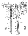
- the reciprocating rectilinear movement of the rod 1 takes place in a direction substantially constant parallel to the mean longitudinal direction L ( Figure 2) of the rod.
- This rectilinear reciprocating movement can be communicated to the rod 1 by any suitable system, in particular a conventional crank rod system driven by a motor-turning in a determined direction.
- the shaft 2 is intended to drive a wiper and comprises a frustoconical part 3 provided with grooves, suitable for cooperating with a corresponding frustoconical part of a wiper assembly head not shown.
- the device D comprises two connecting rods 4, 5 which intersect, articulated, at one of their ends, on the rod 1 and, at their other end, on a part forming a lever 6 integral in rotation with the shaft 2.
- the connecting rod 4 is produced, in the form of a stirrup, in two parallel elements 4a, 4b, symmetrical with respect to the mean plane P (FIG. 1) of the connecting rod and spaced from each other by a distance from (FIG. 1) in a direction perpendicular to this mean plane P.
- the other connecting rod 5 passes between the two elements 4a, 4b of the first connecting rod 4, the mean plane of the second connecting rod 5 being coincident with the mean plane P of the first connecting rod 4.
- the second connecting rod 5 is also produced in two elements 5a, 5h, contiguous as visible in FIG. 1 and in FIG. 4.
- Each of the elements of the connecting rods 4 and 5 is produced in the form of an elementary piece cut from sheet metal, or the like, these parts being provided with holes such as 7 for the passage of hinge pins respectively on the lever 6 and on the rod 1.
- each connecting rod As visible in FIGS. 2 and 3, the elementary parts 4a, 4b and 5a, 5h for the production of each connecting rod are identical and have a shape in an arc of a circle or in crescent, these parts being flat parts.
- the two flat parts 5a and 5b bear against one another by one of their faces.
- Each elementary part 4a, 4b or 5a, 5b of a bielie comprises, around the through hole 7 for an axis, a collar 8, in particular stamped, projecting in a direction perpendicular to the plane of the elementary part considered.
- the projection h (FIG. 5) of the collar relative to the surface of the elementary part (for example 4a) is at least equal to the thickness e of this part.
- the connecting rod 5 can be introduced, between the elements 4a, 4b, of the connecting rod 4 at the time of assembly of these elements; the connecting rod 5 thus put in place cannot escape since at its two ends the superposition of the collars 8 forms a protuberance of transverse dimension g which cannot pass between the elements 4a, 4h.
- the lever 6, in the region of its articulation with each of the connecting rods 4 and 5, comprises two flanges 9, 10 (FIG. 1) spaced from one another in the direction perpendicular to the mean plane of the lever 6, which mean plane coincides with the mean plane P.
- the flanges 9 and 10 define between them a space 11 suitable for receiving the ends of each of the connecting rods 4 and 5, intended to be articulated on the lever, as visible in FIGS. 2 and 3.
- the ends of the connecting rods, provided with holes 7 for the joints, are therefore sandwiched between the flanges 9, 10 of the lever 6.
- This lever is advantageously made of two elementary parts 6a, 6b, substantially in the shape of an isosceles triangle ( Figures 2 and 3) cut from sheet metal; the edge of each elementary part 6a, 6b, corresponding to the base of the isosceles triangle, is offset transversely, so as to constitute the aforesaid flange 9, 10.
- These flanges 9 and 10 are parallel to the mean plane P.
- the elementary parts 6a, 6b are in abutment against each other by the rest of their surface; a transition zone formed by a fraction of an inclined plane such as 12 ( Figures 1 and 2) provides the connection between each flange 9, 10 and the rest of the elementary part 6a, 6b.
- the part 6 may comprise, at its top remote from the flanges 9, 10, a hole serving as passage for a screw or the like for blocking the rotation of the lever 6 on the shaft 2.
- the rod 1, in its region 13 intended to be articulated on one end of said connecting rods 4, 5 has branches 1a, 1b (Figure 1) spaced symmetrically from each other relative to the mean plane of the rod 1, this mean plane being coincident with plane P.
- the branches 1a, 1b define, between them, a space 14 suitable for receiving the end of each of the connecting rods 4 and 5 intended to be articulated on the rod 1.
- the branches 1a, 1b are pierced with facing holes, intended to receive articulation axes 15, 16 (FIGS. 2 and 5) for the ends of the connecting rods 4 and 5.
- the distance between the centers of the holes receiving the axes 15 and 16 has been designated by q in FIG. 2.
- the legs 1a, 1h are fixed, on the rod 1 proper, at an extension such as 17, offset towards the medium plane P and held on the rod 1 by screws, rivets or the like 18. Holes facing each other are also provided towards the ends of the flanges 9 and 10, to receive hinge pins 19 and 20 ( Figures 2 and 4) for the other ends of the connecting rods 4 and 5.
- the hinge pin 19 of the link 4, on the lever 6, is hole in the concavity of the other link 5; it is the same for the articulation axis 20 of the link 5 which is in. the concavity of the link 4.
- Each axis such as 15 or 20 has, on one side, a flat head 15a or 20a of larger diameter which serves as an axial stop, for a direction of movement; at its other end, the shaft is stopped, in the opposite direction, using a washer such as 21 held axially by a split elastic ring 22 anchored in a peripheral groove provided on said axis.
- Elastic washers such as 23 ( Figures 4 and 6) are disposed between the connecting rods 4 and 5, at their collar, and the walls of the flanges 9 and 10 of the lever 6 to remove any lateral play at the joints.
- These elastic washers may include curved portions 23a, in particular diametrically opposite (FIG. 6) adapted to be hung on the lever 6, at the edge thereof and in windows 24 (FIGS. 2 and 3) provided for this purpose.
- Other elastic washers 25 (FIG. 5) without hook, can be provided between the internal walls of the branches 1a, 1h and the connecting rods 4 and 5 at the level of the collars 8, also to eliminate any lateral play at the level of the joints using the axes 15 and 16.
- Sleeves 26 ( Figures 4 and 5) of plastic or the like, are mounted around the axes 15, 16 and 19, 20 to eliminate any radial clearance between said axes and the bore determined by the collars 8 of the elementary parts constituting the connecting rods 4 and 5.
- FIG. 2 represents the extreme position of the rod 1 to the left, and the extreme angular position of the lever 6 and of the corresponding axis 2.
- Figure 3 shows the extreme position of the rod 1 to the right and the corresponding angular position of the lever 6 of the axis 2 which have rotated by an angle C of approximately 100 * relative to the position of FIG. 2.
- the arrangement of the device according to the invention makes it possible to reduce all the traction or compression forces in the same plane P so that the bending moments on the joints are eliminated. This results in a particularly smooth operation of this crankshaft device, as well as better resistance to wear.
- the mass of the elementary parts used can be reduced because these parts are subjected to reduced mechanical stresses. These parts can be produced by cutting relatively thin sheet metal.
Landscapes
- Engineering & Computer Science (AREA)
- Mechanical Engineering (AREA)
- Transmission Devices (AREA)
Applications Claiming Priority (2)
| Application Number | Priority Date | Filing Date | Title |
|---|---|---|---|
| FR8405993 | 1984-04-16 | ||
| FR8405993A FR2562975B1 (fr) | 1984-04-16 | 1984-04-16 | Dispositif d'embiellage, du type quadrilatere articule en croix, notamment pour essuie-glace |
Publications (2)
| Publication Number | Publication Date |
|---|---|
| EP0161168A1 true EP0161168A1 (de) | 1985-11-13 |
| EP0161168B1 EP0161168B1 (de) | 1987-08-12 |
Family
ID=9303197
Family Applications (1)
| Application Number | Title | Priority Date | Filing Date |
|---|---|---|---|
| EP85400714A Expired EP0161168B1 (de) | 1984-04-16 | 1985-04-10 | Kurbelstangenvorrichtung der Art eines kreuzförmig gelenkten Vierecks, insbesondere für Scheibenwischer |
Country Status (5)
| Country | Link |
|---|---|
| EP (1) | EP0161168B1 (de) |
| JP (1) | JPS61143248A (de) |
| DE (1) | DE3560430D1 (de) |
| ES (1) | ES8609633A1 (de) |
| FR (1) | FR2562975B1 (de) |
Cited By (7)
| Publication number | Priority date | Publication date | Assignee | Title |
|---|---|---|---|---|
| GB2191389A (en) * | 1986-06-10 | 1987-12-16 | Optare Limited | Windscreen wiper mechanism |
| FR2642713A1 (fr) * | 1989-02-08 | 1990-08-10 | Daimler Benz Ag | Dispositif d'entrainement pour un essuie-glace, en particulier de vehicules automobiles |
| US5860186A (en) * | 1995-01-17 | 1999-01-19 | Itt Manufacturing Enterprises Inc. | Lift-controlled windscreen wiper device |
| US6422102B1 (en) * | 1999-03-22 | 2002-07-23 | Robert Bosch Gmbh | Wiper drive mechanism with a reversible gear motor |
| EP1084919A3 (de) * | 1999-09-13 | 2003-06-25 | Mitsuba Corporation Co., Ltd. | Wischervorrichtung |
| EP1293404A3 (de) * | 2001-08-02 | 2004-02-11 | Robert Bosch Gmbh | Wischerarm sowie Scheibenwischvorrichtung, insbesondere für ein Kraftfahrzeug |
| WO2006063793A1 (de) * | 2004-12-18 | 2006-06-22 | Valeo Wischersysteme Gmbh | Scheibenwischanlage für fahrzeuge, insbesondere für kraftfahrzeuge |
Families Citing this family (3)
| Publication number | Priority date | Publication date | Assignee | Title |
|---|---|---|---|---|
| JPS63227447A (ja) * | 1987-03-17 | 1988-09-21 | Jidosha Denki Kogyo Co Ltd | クロスリンク式ワイパリンク装置 |
| DE19639593B4 (de) * | 1996-09-26 | 2010-08-19 | Robert Bosch Gmbh | Wischervorrichtung |
| JP2012034911A (ja) * | 2010-08-09 | 2012-02-23 | Aeon Delight Co Ltd | V字型モップ |
Citations (1)
| Publication number | Priority date | Publication date | Assignee | Title |
|---|---|---|---|---|
| GB843903A (en) * | 1957-12-13 | 1960-08-10 | Gen Motors Corp | Improvements in or relating to windscreen wiper actuator mechanisms |
Family Cites Families (1)
| Publication number | Priority date | Publication date | Assignee | Title |
|---|---|---|---|---|
| DE1164858B (de) * | 1958-06-14 | 1964-03-05 | Bosch Gmbh Robert | Zwillingsscheibenwischer fuer Kraftfahrzeuge |
-
1984
- 1984-04-16 FR FR8405993A patent/FR2562975B1/fr not_active Expired
-
1985
- 1985-04-10 EP EP85400714A patent/EP0161168B1/de not_active Expired
- 1985-04-10 DE DE8585400714T patent/DE3560430D1/de not_active Expired
- 1985-04-16 JP JP60079446A patent/JPS61143248A/ja active Pending
- 1985-04-16 ES ES542303A patent/ES8609633A1/es not_active Expired
Patent Citations (1)
| Publication number | Priority date | Publication date | Assignee | Title |
|---|---|---|---|---|
| GB843903A (en) * | 1957-12-13 | 1960-08-10 | Gen Motors Corp | Improvements in or relating to windscreen wiper actuator mechanisms |
Cited By (8)
| Publication number | Priority date | Publication date | Assignee | Title |
|---|---|---|---|---|
| GB2191389A (en) * | 1986-06-10 | 1987-12-16 | Optare Limited | Windscreen wiper mechanism |
| GB2191389B (en) * | 1986-06-10 | 1989-12-13 | Optare Limited | Windscreen wiper mechanism |
| FR2642713A1 (fr) * | 1989-02-08 | 1990-08-10 | Daimler Benz Ag | Dispositif d'entrainement pour un essuie-glace, en particulier de vehicules automobiles |
| US5860186A (en) * | 1995-01-17 | 1999-01-19 | Itt Manufacturing Enterprises Inc. | Lift-controlled windscreen wiper device |
| US6422102B1 (en) * | 1999-03-22 | 2002-07-23 | Robert Bosch Gmbh | Wiper drive mechanism with a reversible gear motor |
| EP1084919A3 (de) * | 1999-09-13 | 2003-06-25 | Mitsuba Corporation Co., Ltd. | Wischervorrichtung |
| EP1293404A3 (de) * | 2001-08-02 | 2004-02-11 | Robert Bosch Gmbh | Wischerarm sowie Scheibenwischvorrichtung, insbesondere für ein Kraftfahrzeug |
| WO2006063793A1 (de) * | 2004-12-18 | 2006-06-22 | Valeo Wischersysteme Gmbh | Scheibenwischanlage für fahrzeuge, insbesondere für kraftfahrzeuge |
Also Published As
| Publication number | Publication date |
|---|---|
| ES542303A0 (es) | 1986-08-01 |
| FR2562975A1 (fr) | 1985-10-18 |
| DE3560430D1 (en) | 1987-09-17 |
| FR2562975B1 (fr) | 1986-08-01 |
| JPS61143248A (ja) | 1986-06-30 |
| EP0161168B1 (de) | 1987-08-12 |
| ES8609633A1 (es) | 1986-08-01 |
Similar Documents
| Publication | Publication Date | Title |
|---|---|---|
| EP0161168B1 (de) | Kurbelstangenvorrichtung der Art eines kreuzförmig gelenkten Vierecks, insbesondere für Scheibenwischer | |
| WO1997021586A1 (fr) | Axe de blocage rapide destine a etre utilise sur un cycle | |
| EP2007995B1 (de) | Gepresste gelenkgabel für kraftfahrzeuglenksäulenkardangelenk | |
| EP0718187B1 (de) | Lagerungsvorrichtung mit bidirektionalem Schwingungsdämpfer für einen Hubschrauberrotor | |
| EP1305176A1 (de) | Elastisches gelenk für eine aufhängung eines kraftfahrzeugs | |
| FR2567221A1 (fr) | Dispositif d'accouplement pour une tige de forage d'une machine de forage par percussion | |
| EP0694455B1 (de) | Trägerplatte eines Scheibenwischermechanismus mit Mitteln zum Befestigen eines Stützlagers | |
| FR2615465A1 (fr) | Assemblage de balai d'essuie-glace et procede pour sa formation | |
| EP1870602B1 (de) | Montageteil zur Verbindung von zwei Elementen miteinander, entsprechende Montagevorrichtung und Anwendung im Automobilbereich | |
| EP0788950B1 (de) | Kraftfahrzeug-Scheibenwischervorrichtung mit Scheibenwischer-Indexierungsmittelnunter Berücksichtigung der Antriebswelle | |
| FR2616715A1 (fr) | Dispositif de suspension de deux roues opposees d'un vehicule et vehicule automobile equipe de ce dispositif | |
| FR2606472A1 (fr) | Dispositif d'articulation entre deux pieces, notamment entre deux elements de mannequin | |
| CH349457A (fr) | Procédé pour l'obtention d'un ensemble mécanique et ensemble mécanique obtenu au moyen de ce procédé | |
| FR3018756B1 (fr) | Dispositif d'entrainement de dispositif d'essuie-glace | |
| FR2567059A3 (fr) | Serre-joint a piece de butee rapportee | |
| FR2761318A1 (fr) | Systeme d'essuyage comportant une traverse qui supporte un ensemble motoreducteur | |
| EP3604051B1 (de) | Einheit zum verbinden eines antriebsarms eines scheibenwischers mit einer motorwelle eines fahrzeugs | |
| FR2768978A1 (fr) | Dispositif d'entrainement pour un systeme d'essuie-glace de vehicule automobile comportant des moyens perfectionnes de fixation d'une rotule | |
| FR2499486A1 (fr) | Raclette d'essuie-glace pour vehicule automobile | |
| FR3066976B1 (fr) | Organe de blocage d'une timonerie dans une position de transport, sous-ensemble de timonerie et timonerie presentant un tel organe de blocage, et procede de mise en place de cet organe de blocage sur une timonerie | |
| EP1663741A1 (de) | Verformbare kurbel für scheibenwischermechanismus mit einem länglichen, vierseitigen loch | |
| FR3066512A1 (fr) | Dispositif d’assemblage de deux pieces de construction de forme allongee | |
| FR2813930A1 (fr) | Ensemble a plateau de pression pour un embrayage a friction | |
| EP0051013A1 (de) | Befestigungselement mit kontrollierbarer Lösbarkeit und Werkzeugausrüstung zu dessen Herstellung | |
| FR2984825A1 (fr) | Dispositif d'actionnement d'essuie-glace en forme de quadrilatere articule |
Legal Events
| Date | Code | Title | Description |
|---|---|---|---|
| PUAI | Public reference made under article 153(3) epc to a published international application that has entered the european phase |
Free format text: ORIGINAL CODE: 0009012 |
|
| 17P | Request for examination filed |
Effective date: 19850411 |
|
| AK | Designated contracting states |
Designated state(s): DE IT |
|
| 17Q | First examination report despatched |
Effective date: 19870127 |
|
| RAP1 | Party data changed (applicant data changed or rights of an application transferred) |
Owner name: EQUIPEMENTS AUTOMOBILES MARCHAL |
|
| GRAA | (expected) grant |
Free format text: ORIGINAL CODE: 0009210 |
|
| AK | Designated contracting states |
Kind code of ref document: B1 Designated state(s): DE IT |
|
| ITF | It: translation for a ep patent filed |
Owner name: JACOBACCI & PERANI S.P.A. |
|
| REF | Corresponds to: |
Ref document number: 3560430 Country of ref document: DE Date of ref document: 19870917 |
|
| PLBE | No opposition filed within time limit |
Free format text: ORIGINAL CODE: 0009261 |
|
| STAA | Information on the status of an ep patent application or granted ep patent |
Free format text: STATUS: NO OPPOSITION FILED WITHIN TIME LIMIT |
|
| 26N | No opposition filed | ||
| PG25 | Lapsed in a contracting state [announced via postgrant information from national office to epo] |
Ref country code: DE Effective date: 19890103 |