EP1870602B1 - Montageteil zur Verbindung von zwei Elementen miteinander, entsprechende Montagevorrichtung und Anwendung im Automobilbereich - Google Patents
Montageteil zur Verbindung von zwei Elementen miteinander, entsprechende Montagevorrichtung und Anwendung im Automobilbereich Download PDFInfo
- Publication number
- EP1870602B1 EP1870602B1 EP07290775A EP07290775A EP1870602B1 EP 1870602 B1 EP1870602 B1 EP 1870602B1 EP 07290775 A EP07290775 A EP 07290775A EP 07290775 A EP07290775 A EP 07290775A EP 1870602 B1 EP1870602 B1 EP 1870602B1
- Authority
- EP
- European Patent Office
- Prior art keywords
- assembly
- piece
- head
- arm
- assembly position
- Prior art date
- Legal status (The legal status is an assumption and is not a legal conclusion. Google has not performed a legal analysis and makes no representation as to the accuracy of the status listed.)
- Active
Links
- 238000006073 displacement reaction Methods 0.000 claims 1
- 239000011324 bead Substances 0.000 description 8
- 230000014759 maintenance of location Effects 0.000 description 2
- 238000007747 plating Methods 0.000 description 2
- 230000007704 transition Effects 0.000 description 2
- 238000010276 construction Methods 0.000 description 1
- 230000008878 coupling Effects 0.000 description 1
- 238000010168 coupling process Methods 0.000 description 1
- 238000005859 coupling reaction Methods 0.000 description 1
Images


Classifications
-
- B—PERFORMING OPERATIONS; TRANSPORTING
- B60—VEHICLES IN GENERAL
- B60R—VEHICLES, VEHICLE FITTINGS, OR VEHICLE PARTS, NOT OTHERWISE PROVIDED FOR
- B60R11/00—Arrangements for holding or mounting articles, not otherwise provided for
-
- F—MECHANICAL ENGINEERING; LIGHTING; HEATING; WEAPONS; BLASTING
- F16—ENGINEERING ELEMENTS AND UNITS; GENERAL MEASURES FOR PRODUCING AND MAINTAINING EFFECTIVE FUNCTIONING OF MACHINES OR INSTALLATIONS; THERMAL INSULATION IN GENERAL
- F16B—DEVICES FOR FASTENING OR SECURING CONSTRUCTIONAL ELEMENTS OR MACHINE PARTS TOGETHER, e.g. NAILS, BOLTS, CIRCLIPS, CLAMPS, CLIPS OR WEDGES; JOINTS OR JOINTING
- F16B21/00—Means for preventing relative axial movement of a pin, spigot, shaft or the like and a member surrounding it; Stud-and-socket releasable fastenings
- F16B21/02—Releasable fastening devices locking by rotation
-
- F—MECHANICAL ENGINEERING; LIGHTING; HEATING; WEAPONS; BLASTING
- F16—ENGINEERING ELEMENTS AND UNITS; GENERAL MEASURES FOR PRODUCING AND MAINTAINING EFFECTIVE FUNCTIONING OF MACHINES OR INSTALLATIONS; THERMAL INSULATION IN GENERAL
- F16B—DEVICES FOR FASTENING OR SECURING CONSTRUCTIONAL ELEMENTS OR MACHINE PARTS TOGETHER, e.g. NAILS, BOLTS, CIRCLIPS, CLAMPS, CLIPS OR WEDGES; JOINTS OR JOINTING
- F16B5/00—Joining sheets or plates, e.g. panels, to one another or to strips or bars parallel to them
- F16B5/06—Joining sheets or plates, e.g. panels, to one another or to strips or bars parallel to them by means of clamps or clips
- F16B5/0607—Joining sheets or plates, e.g. panels, to one another or to strips or bars parallel to them by means of clamps or clips joining sheets or plates to each other
- F16B5/0621—Joining sheets or plates, e.g. panels, to one another or to strips or bars parallel to them by means of clamps or clips joining sheets or plates to each other in parallel relationship
- F16B5/0635—Joining sheets or plates, e.g. panels, to one another or to strips or bars parallel to them by means of clamps or clips joining sheets or plates to each other in parallel relationship fastened over the edges of the sheets or plates
-
- B—PERFORMING OPERATIONS; TRANSPORTING
- B60—VEHICLES IN GENERAL
- B60R—VEHICLES, VEHICLE FITTINGS, OR VEHICLE PARTS, NOT OTHERWISE PROVIDED FOR
- B60R13/00—Elements for body-finishing, identifying, or decorating; Arrangements or adaptations for advertising purposes
- B60R13/08—Insulating elements, e.g. for sound insulation
- B60R13/0838—Insulating elements, e.g. for sound insulation for engine compartments
Definitions
- the invention mainly relates to an assembly part of a first element on a second element.
- the invention also relates to an assembly device comprising such a part.
- the invention finds particular application to ensure the assembly of a cache type style screen motor of a motor vehicle.
- the engine of a motor vehicle generates noise and vibrations that can be dampened by the presence of a type cache screen attached to the engine.
- the publication FR 2 857 065 discloses an interlocking coupling device for connecting a cache style screen to a motor.
- This device comprises a stud connected to the cover style in which engages a pin secured to the engine block.
- Such a device has the major disadvantage of using several pieces of complex shape and construction that generate the presence of multiple means of connection between the pin, the pad and the motor block.
- the present invention has the main object to overcome the aforementioned drawbacks by providing a simpler configuration of assembly part for an efficiency at least equal.
- the assembly part of the invention which is defined by the technical features of the independent claim 1, is essentially characterized in that it comprises rotary contact bearing means on the first element and means for assembling the first element to the second element which are activatable by rotation of this assembly part mounted on the first element and passing from at least one pre-assembly position to an assembly position.
- the assembly part comprises first locking means on the first element in the pre-assembly position and second unlocking means on the first element in the assembly position.
- the assembly part comprises a body surmounted by a rotating contact bearing head on the upper face of the first element when said body is housed through an orifice of this first element, and it comprises an arm which extends integrally from the body of the assembly part and which comprises means for fixed retention of the second element against the first element in the assembly position.
- the arm of the assembly piece can extend from a lower portion of the body, so that when said body is housed through the orifice of the first element, the arm extends under the lower face. of the first element, and in that the free end of the arm comprises at least one rib, preferably two parallel ribs, ensuring the plating of the second element against the first element in the assembly position.
- the lower face of the circular support head comprises at least one bead which is adapted to be indexed in at least two conjugate grooves formed on the upper face of the first part to, respectively, adopt the position of pre-assembly and the assembly position
- the body comprises at least one deformable detent tab axially facing the bead of the circular head so that in the pre-assembly and assembly positions, the latching lug comes s' snap under the first piece, which results in this first piece engages between the leg snap and the circular head of the assembly part.
- the lower face of the circular support head comprises two beads extending radially around the body being diametrically opposed and the upper face of the first element comprises a pair of grooves for the pre-assembly and a pair of grooves for assembly. , these four grooves being two diametrically opposed pairs and each spaced at an angle of 90 ° so that the transition from the pre-assembly position to the assembly position is performed by rotating a quarter turn of the head bearing of the assembly part in plane on the first element with respect to the first substantially perpendicular plane.
- the upper face of the bearing head comprises a central groove for accommodating an object of conjugated form, for example a coin, to manually exert the rotational force required to move from the pre-assembly position to the position assembly.
- an object of conjugated form for example a coin
- the invention also relates to a device for assembling a first element to a second element comprising the assembly part defined above and comprising means facilitating the assembly of the first element to the second element by loosening the forces exerted by the workpiece. assembling on the first element during an intermediate release position and increasing the fixing forces of the assembly part on the first element to the transition from the intermediate position of release to the pre-assembly or assembly position.
- the device of the invention comprises at least one hollow zone formed on the upper face of the first element while extending around the orifice formed in this element and between two adjacent grooves, and this hollow zone comprises two ramps which go up each near the groove adjacent, so that the passage of the assembly part of an intermediate release position in which the bead of the bearing head is in the hollow zone to one or the other premounted indexed positions and assembly, lead to an axial upward movement of the assembly part relative to the first element, and thus the exercise of a clamping force of the second element on the first element when the assembly part reaches the assembly position.
- the invention relates to the application of the assembly part and the assembly device defined above, to the assembly of a type cache screen to a motor vehicle engine.
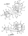
- the assembly part 1 of the invention comprises a body 2 which extends along a longitudinal axis XX ', which is surmounted by a circular flat head 3 and which integrally extends an arm 4.
- the arm 4 has a first portion 6 which extends along a longitudinal axis YY 'perpendicular to the longitudinal axis XX' of the body 5 from the lower end 5 of the body 2 to a second portion 7 which extends in the longitudinal extension of the first part 6 being slightly inclined towards the head 3, these first 6 and second 7 parts having a rectangular cross section.
- the second part 7 ends, on the opposite side to the first part 6, by an assembly end 8 which has two parallel ribs of rectangular cross section 9,10 extending perpendicularly to the longitudinal axis YY 'of the arm 4 and a portion 11 projecting from the arm 4 in the extension of the two ribs 9, 10 and whose upper face 12 is inclined in the direction opposite to the head 3.
- the body 2 is of generally cylindrical shape having two flat faces 13,14 diametrically opposite being aligned with the longitudinal axis YY 'of the arm 4 and which each extend along the longitudinal axis XX' of the body 2 from the face 14 of the flat head 3 to a partially arcuate planar face 15,16 approximately located at the same level as the upper face 17 of the first portion 6 of the arm 4 and from which extends perpendicularly a respective latching lug 18 19.
- Each latching lug 18, 19 runs along the corresponding plane face 13, 14 at a distance from the latter and has a first portion 20, 21 with a rectangular cross-section and a second portion 22, 23 radially outwardly inclined with a upper planar bearing surface 24,25 opposite the lower face 14 of the head 3 of the assembly part 1.
- the lower face 14 of the circular flat head 3 has two diametrically opposed beads 26, 27, each extending radially from the body 2 to the periphery 30 of the head 3 while being disposed longitudinally on the surfaces of the face.
- planar support 24,25 of the latching lugs 18,19 so that the first element can engage between the head 3 and the latching lug 18,19 as will be explained later.
- the upper face 31 of the head 3 has a groove 32 in which can be partially inserted a circular piece, for example a coin, in order to be able to turn the assembly piece about the axis XX 'when is mounted on the screen type cache style.
- a circular piece for example a coin
- the type cache type screen 35 is substantially planar and comprises a circular through hole 36 of diameter substantially equal to the diameter of the body 2 of the assembly part.
- the upper face 37 of the screen 35 has an annular rim 38 all around the orifice 36 which has four indexing grooves 39, 40, 41, 42 organized in pairs, or a pair for the pre-assembly 3941 and a pair of grooves for the assembly 4042, for each of which the two corresponding grooves 39,41; 40,42 are diametrically opposed.
- the four grooves 39, 40, 41, 42 are spaced 90 ° from each other with respect to the axis ZZ 'of the circular orifice 36 and extend radially on the annular edge 38 over the entire width of this edge 38 from its inner periphery 43.
- edge 38 also comprises two diametrically opposed arcuate hollow zones 44, 45 which extend around the orifice 36 between two adjacent grooves 39, 40, 41, 42 and which each have at their two respective ends 46, 47 , 48.49 a ramp 50.51; 52,53 ending near the corresponding groove 39,40,41,42.
- the assembly part 1 is introduced into the orifice 36 of the screen 35 by translation movement downwards along the arrow A of its arm 4 through this orifice 36.
- the assembly part 1 is tilted according to the arrow B of the figure 6 and is placed in pre-assembly position P represented on the figure 7 passing through an intermediate release position such as that shown on the figure 8 for which the latching lugs 18, 19 have passed through the orifice 36 of the screen 35, the two beads 26, 27 of the head of the assembly part 3 are positioned in each of the two hollow zones 44, 45 of the screen 35 which results in the concomitant release of the latching lugs 18, 19 under this screen 35.
- the assembly part 1 can be transported fixed to the screen without risk of loss of this assembly part 1.
- the assembly part 1 passes from the pre-assembly position of the figure 7 at the assembly position of the figure 9 by rotating a quarter of a turn of this assembly piece around the axes ZZ 'and XX' according to the arrow D of the figure 8 and 9 this rotation can be performed using a coin introduced into the groove 32 made on the upper face 31 of the head 3 of the assembly part 1.
- the gadroons 26,27 are found vis-a-vis with the hollow zones 44,45. In this way during clipping, the clips 18, 19 have enough space to relax properly under the surface of the cover 56.
- the rotation in the trigonometric direction of the quarter turn 3 of a few degrees comes into play. contact the gadroons 26,27 with the inclined surfaces of the hollow areas 50,53. By continuing the rotation the clips 18,19 come to rest under the surface of the cover 56 and put under stress quarter turn 3.
- the flutes 26,27 engage in the grooves 39,41 which mark the position of pre-assembly quarter turn 3.
- a new rotation of 45 ° engages the gadroons 26,27 in the grooves 42,40 which mark the final assembly position on vehicle.
- the particular configuration of the assembly part 1 allows the system to be held stably in the pre-assembly position, during the entire transport to the final assembly.
- the 44,45 hollow zones are essential for the proper hooking of the quarter turn 3, in order to obtain a correct clipping during assembly. Without this hollow zone, the clips 18, 19 can not relax under the surface of the cover 56.
Claims (9)
- Teil zum Zusammenbauen eines ersten Elements mit einem zweiten Element, umfassend Drehkontaktstützmittel (3, 14) auf dem ersten Element (35) und Mittel (4, 9, 10) zum Zusammenbauen des ersten Elements (35) mit dem zweiten Element (55), die durch Drehung dieses Zusammenbauteils (1), das an dem ersten Element (35) angebracht ist, und durch Übergang von mindestens einer Vormontageposition auf eine Zusammenbauposition, aktivierbar sind, dadurch gekennzeichnet, dass es erste Verriegelungsmittel (18, 19, 26, 27, 3941) auf dem ersten Element (35) in der Vormontageposition und zweite Verriegelungsmittel (18, 19, 26, 27, 4042) auf dem ersten Element (35) in der Zusammenbauposition umfasst.
- Zusammenbauteil nach Anspruch 1, dadurch gekennzeichnet, dass es einen Körper (2) umfasst, den ein Kopf (3) überragt, der sich mit Drehkontakt auf der oberen Seite (37) des ersten Elements (35) abstützt, wenn der Körper (2) durch eine Öffnung (36) dieses ersten Elements (35) hindurch aufgenommen wird, und dass es einen Arm (4) umfasst, der sich fest verbunden von dem Körper (2) des Zusammenbauteils (1) aus erstreckt und der Mittel (9, 10) zum Festhalten des zweiten Elements (55) an dem ersten Element (35) in der Zusammenbauposition umfasst.
- Zusammenbauteil nach Anspruch 2, dadurch gekennzeichnet, dass der Arm (4) sich von einem unteren Abschnitt (5) des Körpers (2) aus erstreckt, so dass wenn der Körper (2) durch die Öffnung (36) des ersten Elements (35) hindurch aufgenommen wird, der Arm (4) sich unter der unteren Seite (56) des ersten Elements (35) erstreckt, und dass das freie Ende (11) des Arms (4) mindestens eine Rippe (9, 10), bevorzugt zwei parallele Rippen (9, 10) umfasst, die das Andrücken des zweiten Elements (55) an das erste Element (35) in der Zusammenbauposition sicherstellt bzw. sicherstellen.
- Zusammenbauteil nach Anspruch 3, dadurch gekennzeichnet, dass die untere Seite (14) des kreisförmigen Stützkopfes (3) mindestens eine Wulst (26, 27) umfasst, die dazu geeignet ist, sich in mindestens zwei zugeordneten Rillen (39, 41; 41,42), die auf der oberen Seite (37) des ersten Teils (35) ausgebildet sind, zu positionieren, um jeweils die Vormontageposition und die Zusammenbauposition einzunehmen, und dass der Körper (2) mindestens eine verformbare Einrastlasche (18, 19) axial gegenüber der Wulst (26, 27) des kreisförmigen Kopfes (3) umfasst, so dass die Einrastlasche (18, 19) in den Vormontage- und Zusammenbaupositionen unter dem ersten Teil (35) einrastet, woraus sich ergibt, dass dieses erste Teil (35) zwischen der Einrastlasche (18, 19) und dem kreisförmigen Kopf (3) des Zusammenbauteils (1) eingreift.
- Zusammenbauteil nach Anspruch 4, dadurch gekennzeichnet, dass die untere Seite (14) des kreisförmigen Stützkopfes (3) zwei Wülste (26, 27) umfasst, die sich radial um den Körper (2) herum erstrecken, wobei sie sich diametral gegenüberstehen, und dass die obere Seite (37) des ersten Elements (35) ein Rillenpaar für die Vormontage (3941) und ein Rillenpaar für den Zusammenbau (4042) umfasst, wobei diese vier Rillen (39, 40, 41, 42) sich paarweise diametral gegenüberstehen und jeweils um einen Winkel von 90° beabstandet sind, so dass der Übergang von der Vormontageposition auf die Zusammenbauposition durch eine Viertelumdrehung des Stützkopfes (3) des Zusammenbauteils (1) flach auf dem ersten Element im Verhältnis zu der ersten Ebene im Wesentlichen rechtwinklig erfolgt.
- Zusammenbauteil nach einem der Ansprüche 2 bis 5, dadurch gekennzeichnet, dass die obere Seite (31) des Stützkopfes (3) eine mittlere Rille (32) umfasst, die es ermöglicht, einen passend geformten Gegenstand aufzunehmen, z.B. ein Geldstück, um manuell die Drehkraft auszuüben, die notwendig ist, um von der Vormontageposition auf die Zusammenbauposition überzugehen.
- Vorrichtung zum Zusammenbauen eines ersten Elements mit einem zweiten Element, die das Zusammenbauteil nach einem der Ansprüche 1 bis 6 umfasst und dadurch gekennzeichnet ist, dass sie Mittel umfasst, die den Zusammenbau (44, 45; 50, 51, 52, 53) des ersten Elements (35) mit dem zweiten Element (55) durch Entspannung der Kräfte, die von dem Zusammenbauteil auf das erste Element während einer Entspannungszwischenposition ausgeübt werden, und durch Erhöhung der Kräfte zum Befestigen des Zusammenbauteils (1) an dem ersten Element (35) beim Übergang von der Entspannungszwischenposition auf die Vormontage- oder Zusammenbauposition erleichtern.
- Vorrichtung nach Anspruch 7, umfassend die Zusammenbauvorrichtung nach einem der Ansprüche 5 bis 7, dadurch gekennzeichnet, dass sie mindestens einen Hohlbereich (44, 45) umfasst, der auf der oberen Seite (37) des ersten Elements (35) ausgebildet ist, wobei er sich um die Öffnung (36) herum, die in diesem Element (35) gebildet ist, und zwischen zwei nebeneinanderliegenden Rillen (39, 40; 41, 42) erstreckt, und dass dieser Hohlbereich (44, 45) zwei Rampen (50, 51; 52, 53) umfasst, die jeweils bis in die Nähe der angrenzenden Rille (39, 40, 41, 42) ansteigen, so dass der Übergang des Zusammenbauteils (1) von einer Entspannungszwischenposition, in der die Wulst des Stützkopfes (26, 27) sich in dem Hohlbereich (44, 45) befindet, auf die eine oder andere der indexierten Vormontage- und Zusammenbaupositionen zu einer Axialverlagerung des Zusammenbauteils (1) mit Bezug auf das erste Element (35) nach oben und somit zur Ausübung einer Klemmkraft des zweiten Elements (55) auf das erste Element (35), wenn das Zusammenbauteil (1) die Zusammenbauposition erreicht, führt.
- Anwendung des erfindungsgemäßen Zusammenbauteils nach Anspruch 1 bis 6 und der Zusammenbauvorrichtung nach Anspruch 7 und 8 auf den Zusammenbau einer Abdeckung nach Art einer Stilblende an einem Kraftfahrzeugmotor.
Applications Claiming Priority (1)
| Application Number | Priority Date | Filing Date | Title |
|---|---|---|---|
| FR0652607A FR2902846B1 (fr) | 2006-06-22 | 2006-06-22 | Piece d'assemblage de deux elements entre eux, dispositif d'assemblage associe et application au domaine de l'automobile. |
Publications (2)
| Publication Number | Publication Date |
|---|---|
| EP1870602A1 EP1870602A1 (de) | 2007-12-26 |
| EP1870602B1 true EP1870602B1 (de) | 2010-04-14 |
Family
ID=37708310
Family Applications (1)
| Application Number | Title | Priority Date | Filing Date |
|---|---|---|---|
| EP07290775A Active EP1870602B1 (de) | 2006-06-22 | 2007-06-21 | Montageteil zur Verbindung von zwei Elementen miteinander, entsprechende Montagevorrichtung und Anwendung im Automobilbereich |
Country Status (5)
| Country | Link |
|---|---|
| EP (1) | EP1870602B1 (de) |
| AT (1) | ATE464483T1 (de) |
| DE (1) | DE602007005872D1 (de) |
| ES (1) | ES2344368T3 (de) |
| FR (1) | FR2902846B1 (de) |
Families Citing this family (5)
| Publication number | Priority date | Publication date | Assignee | Title |
|---|---|---|---|---|
| CA2635620C (en) | 2008-06-23 | 2014-02-11 | Scott Godfrey | Lamp retaining system for traffic signals |
| US7794122B2 (en) | 2008-06-23 | 2010-09-14 | Scott Godfrey | Lamp retaining system for traffic signals |
| ES2844923T3 (es) | 2017-07-07 | 2021-07-23 | Antolin Grupo Ing Sa | Conjunto de cierre de cuarto de vuelta, panel de vehículo de polipropileno expandido y una placa de hoja metálica de vehículo |
| DE102020125523A1 (de) | 2020-09-30 | 2022-03-31 | Bjb Gmbh & Co. Kg | Befestigungselement für Leuchtmittel-Platinen |
| DE202020105933U1 (de) * | 2020-10-16 | 2020-11-17 | Samson Aktiengesellschaft | Deckel mit Verschluss |
Family Cites Families (3)
| Publication number | Priority date | Publication date | Assignee | Title |
|---|---|---|---|---|
| DE2328412C3 (de) * | 1973-06-04 | 1975-11-27 | Springfix-Befestigungstechnik Gmbh, 7335 Salach | Befestigungselement |
| CA2270085A1 (en) * | 1999-04-23 | 2000-10-23 | Constantinos J. Joannou | Latch fastener mechanism for thin sheet materials |
| US6267543B1 (en) * | 1999-10-13 | 2001-07-31 | Avaya Technology Corp. | Latch with spring |
-
2006
- 2006-06-22 FR FR0652607A patent/FR2902846B1/fr not_active Expired - Fee Related
-
2007
- 2007-06-21 DE DE602007005872T patent/DE602007005872D1/de active Active
- 2007-06-21 AT AT07290775T patent/ATE464483T1/de not_active IP Right Cessation
- 2007-06-21 ES ES07290775T patent/ES2344368T3/es active Active
- 2007-06-21 EP EP07290775A patent/EP1870602B1/de active Active
Also Published As
| Publication number | Publication date |
|---|---|
| ATE464483T1 (de) | 2010-04-15 |
| DE602007005872D1 (de) | 2010-05-27 |
| ES2344368T3 (es) | 2010-08-25 |
| EP1870602A1 (de) | 2007-12-26 |
| FR2902846A1 (fr) | 2007-12-28 |
| FR2902846B1 (fr) | 2009-11-20 |
Similar Documents
| Publication | Publication Date | Title |
|---|---|---|
| EP1012483B1 (de) | Anordnung zum befestigen eines rohrförmigen elements auf einem teil der struktur einer kraftfahrzeugkarosserie | |
| EP0024976B1 (de) | Vorrichtung zum Regeln der relativen Neigung zweier Teile, insbesondere der zwei Teile eines Fahrzeugsitzes | |
| FR2712226A1 (fr) | Dispositif de tension pour une chaîne de sciage passant sur un guide de sciage dans une scie à chaîne motorisée. | |
| FR2915537A1 (fr) | Dispositif de serrage | |
| EP1870602B1 (de) | Montageteil zur Verbindung von zwei Elementen miteinander, entsprechende Montagevorrichtung und Anwendung im Automobilbereich | |
| WO2004028236A2 (fr) | Dispositif de fixation de lames a un arbre rotatif et machine agricole equipee d’un tel dispositif | |
| EP2890906B1 (de) | Buchse zur befestigung eines bolzens an einem träger und entsprechende anordnung | |
| EP0196966B1 (de) | Kupplungsausrücker, insbesondere für ein Kraftfahrzeug | |
| EP0788950B1 (de) | Kraftfahrzeug-Scheibenwischervorrichtung mit Scheibenwischer-Indexierungsmittelnunter Berücksichtigung der Antriebswelle | |
| EP2678212A1 (de) | Vorrichtung zur befestigung eines reserverades eines fahrzeuges | |
| EP1471269A2 (de) | Vorrichtung zur Verriegelung einer Mutter auf einem Gewinde zur Verbindung eines Werkstücks durch Festschrauben der Mutter an ein anderes mit diesem Gewinde solidarischem Werkstück | |
| EP0936128B1 (de) | Lenksystem, Lenkrad und Lenkradsäule für ein solches System | |
| FR2581717A1 (fr) | Raccord pour l'assemblage angulaire d'organes tubulaires | |
| WO2021047812A1 (fr) | Maneton, boîte à rotule et système de tringlerie d'actionnement d'essuie-glaces correspondant et son procédé d'assemblage | |
| EP0936127B1 (de) | Fahrzeuglenkrad | |
| FR2868031A1 (fr) | Entretoise a montage sans soudures pour berceau de support de train avant ou arriere d'un vehicule automobile | |
| EP2022921B1 (de) | Befestigungsvorrichtung für einen Mitnehmer einer Fensterscheibe bestehend aus Schraubenmuttern und Schrauben | |
| EP2745887B1 (de) | Fixierung für Schuhwerk auf einem Sportgerät | |
| EP3392086B1 (de) | Ringförmige festzurranordnung auf einer haltestruktur, wie eine einfassung oder einem boden, insbesondere zum beladen eines transportfahrzeugs | |
| FR2771694A1 (fr) | Essuie-glace de vehicule automobile comportant des moyens de liaison directe entre un balai et un bras d'essuie-glace | |
| EP0903272B1 (de) | Kraftfahrzeugscheibenwischer mit verbesserter Vorrichtung für die Gelenkverbindung zwischen einem Wischblatt und einem Wischarm | |
| EP0589798A1 (de) | Scheibenwischerarm mit geformtem Gelenkteil, insbesondere für Kraftfahrzeuge | |
| FR2724893A1 (fr) | Platine-support pour un dispositif d'essuie-glace de vehicule automobile | |
| FR2930232A1 (fr) | Ensemble pour cycle, fourche et cadre correspondants. | |
| FR2579704A1 (fr) | Butee de debrayage a plaque d'appui en u et agrafes d'un seul tenant avec celle-ci, notamment pour vehicule automobile |
Legal Events
| Date | Code | Title | Description |
|---|---|---|---|
| PUAI | Public reference made under article 153(3) epc to a published international application that has entered the european phase |
Free format text: ORIGINAL CODE: 0009012 |
|
| AK | Designated contracting states |
Kind code of ref document: A1 Designated state(s): AT BE BG CH CY CZ DE DK EE ES FI FR GB GR HU IE IS IT LI LT LU LV MC MT NL PL PT RO SE SI SK TR |
|
| AX | Request for extension of the european patent |
Extension state: AL BA HR MK YU |
|
| 17P | Request for examination filed |
Effective date: 20080526 |
|
| 17Q | First examination report despatched |
Effective date: 20080709 |
|
| AKX | Designation fees paid |
Designated state(s): AT BE BG CH CY CZ DE DK EE ES FI FR GB GR HU IE IS IT LI LT LU LV MC MT NL PL PT RO SE SI SK TR |
|
| GRAP | Despatch of communication of intention to grant a patent |
Free format text: ORIGINAL CODE: EPIDOSNIGR1 |
|
| GRAS | Grant fee paid |
Free format text: ORIGINAL CODE: EPIDOSNIGR3 |
|
| GRAA | (expected) grant |
Free format text: ORIGINAL CODE: 0009210 |
|
| AK | Designated contracting states |
Kind code of ref document: B1 Designated state(s): AT BE BG CH CY CZ DE DK EE ES FI FR GB GR HU IE IS IT LI LT LU LV MC MT NL PL PT RO SE SI SK TR |
|
| REG | Reference to a national code |
Ref country code: GB Ref legal event code: FG4D Free format text: NOT ENGLISH |
|
| REG | Reference to a national code |
Ref country code: CH Ref legal event code: EP |
|
| REG | Reference to a national code |
Ref country code: IE Ref legal event code: FG4D Free format text: LANGUAGE OF EP DOCUMENT: FRENCH |
|
| REF | Corresponds to: |
Ref document number: 602007005872 Country of ref document: DE Date of ref document: 20100527 Kind code of ref document: P |
|
| REG | Reference to a national code |
Ref country code: NL Ref legal event code: VDEP Effective date: 20100414 |
|
| REG | Reference to a national code |
Ref country code: ES Ref legal event code: FG2A Ref document number: 2344368 Country of ref document: ES Kind code of ref document: T3 |
|
| LTIE | Lt: invalidation of european patent or patent extension |
Effective date: 20100414 |
|
| PG25 | Lapsed in a contracting state [announced via postgrant information from national office to epo] |
Ref country code: NL Free format text: LAPSE BECAUSE OF FAILURE TO SUBMIT A TRANSLATION OF THE DESCRIPTION OR TO PAY THE FEE WITHIN THE PRESCRIBED TIME-LIMIT Effective date: 20100414 Ref country code: SE Free format text: LAPSE BECAUSE OF FAILURE TO SUBMIT A TRANSLATION OF THE DESCRIPTION OR TO PAY THE FEE WITHIN THE PRESCRIBED TIME-LIMIT Effective date: 20100414 Ref country code: LT Free format text: LAPSE BECAUSE OF FAILURE TO SUBMIT A TRANSLATION OF THE DESCRIPTION OR TO PAY THE FEE WITHIN THE PRESCRIBED TIME-LIMIT Effective date: 20100414 |
|
| REG | Reference to a national code |
Ref country code: IE Ref legal event code: FD4D |
|
| PG25 | Lapsed in a contracting state [announced via postgrant information from national office to epo] |
Ref country code: SI Free format text: LAPSE BECAUSE OF FAILURE TO SUBMIT A TRANSLATION OF THE DESCRIPTION OR TO PAY THE FEE WITHIN THE PRESCRIBED TIME-LIMIT Effective date: 20100414 Ref country code: IS Free format text: LAPSE BECAUSE OF FAILURE TO SUBMIT A TRANSLATION OF THE DESCRIPTION OR TO PAY THE FEE WITHIN THE PRESCRIBED TIME-LIMIT Effective date: 20100814 Ref country code: LV Free format text: LAPSE BECAUSE OF FAILURE TO SUBMIT A TRANSLATION OF THE DESCRIPTION OR TO PAY THE FEE WITHIN THE PRESCRIBED TIME-LIMIT Effective date: 20100414 Ref country code: FI Free format text: LAPSE BECAUSE OF FAILURE TO SUBMIT A TRANSLATION OF THE DESCRIPTION OR TO PAY THE FEE WITHIN THE PRESCRIBED TIME-LIMIT Effective date: 20100414 Ref country code: AT Free format text: LAPSE BECAUSE OF FAILURE TO SUBMIT A TRANSLATION OF THE DESCRIPTION OR TO PAY THE FEE WITHIN THE PRESCRIBED TIME-LIMIT Effective date: 20100414 |
|
| BERE | Be: lapsed |
Owner name: FABI AUTOMOBILE Effective date: 20100630 Owner name: PEUGEOT CITROEN AUTOMOBILES S.A. Effective date: 20100630 |
|
| PG25 | Lapsed in a contracting state [announced via postgrant information from national office to epo] |
Ref country code: PL Free format text: LAPSE BECAUSE OF FAILURE TO SUBMIT A TRANSLATION OF THE DESCRIPTION OR TO PAY THE FEE WITHIN THE PRESCRIBED TIME-LIMIT Effective date: 20100414 Ref country code: CY Free format text: LAPSE BECAUSE OF FAILURE TO SUBMIT A TRANSLATION OF THE DESCRIPTION OR TO PAY THE FEE WITHIN THE PRESCRIBED TIME-LIMIT Effective date: 20100519 |
|
| PG25 | Lapsed in a contracting state [announced via postgrant information from national office to epo] |
Ref country code: EE Free format text: LAPSE BECAUSE OF FAILURE TO SUBMIT A TRANSLATION OF THE DESCRIPTION OR TO PAY THE FEE WITHIN THE PRESCRIBED TIME-LIMIT Effective date: 20100414 Ref country code: DK Free format text: LAPSE BECAUSE OF FAILURE TO SUBMIT A TRANSLATION OF THE DESCRIPTION OR TO PAY THE FEE WITHIN THE PRESCRIBED TIME-LIMIT Effective date: 20100414 Ref country code: MC Free format text: LAPSE BECAUSE OF NON-PAYMENT OF DUE FEES Effective date: 20100630 Ref country code: PT Free format text: LAPSE BECAUSE OF FAILURE TO SUBMIT A TRANSLATION OF THE DESCRIPTION OR TO PAY THE FEE WITHIN THE PRESCRIBED TIME-LIMIT Effective date: 20100816 Ref country code: IE Free format text: LAPSE BECAUSE OF FAILURE TO SUBMIT A TRANSLATION OF THE DESCRIPTION OR TO PAY THE FEE WITHIN THE PRESCRIBED TIME-LIMIT Effective date: 20100414 |
|
| PLBE | No opposition filed within time limit |
Free format text: ORIGINAL CODE: 0009261 |
|
| STAA | Information on the status of an ep patent application or granted ep patent |
Free format text: STATUS: NO OPPOSITION FILED WITHIN TIME LIMIT |
|
| PG25 | Lapsed in a contracting state [announced via postgrant information from national office to epo] |
Ref country code: RO Free format text: LAPSE BECAUSE OF FAILURE TO SUBMIT A TRANSLATION OF THE DESCRIPTION OR TO PAY THE FEE WITHIN THE PRESCRIBED TIME-LIMIT Effective date: 20100414 Ref country code: CZ Free format text: LAPSE BECAUSE OF FAILURE TO SUBMIT A TRANSLATION OF THE DESCRIPTION OR TO PAY THE FEE WITHIN THE PRESCRIBED TIME-LIMIT Effective date: 20100414 Ref country code: SK Free format text: LAPSE BECAUSE OF FAILURE TO SUBMIT A TRANSLATION OF THE DESCRIPTION OR TO PAY THE FEE WITHIN THE PRESCRIBED TIME-LIMIT Effective date: 20100414 |
|
| 26N | No opposition filed |
Effective date: 20110117 |
|
| PG25 | Lapsed in a contracting state [announced via postgrant information from national office to epo] |
Ref country code: GR Free format text: LAPSE BECAUSE OF FAILURE TO SUBMIT A TRANSLATION OF THE DESCRIPTION OR TO PAY THE FEE WITHIN THE PRESCRIBED TIME-LIMIT Effective date: 20100715 Ref country code: MT Free format text: LAPSE BECAUSE OF FAILURE TO SUBMIT A TRANSLATION OF THE DESCRIPTION OR TO PAY THE FEE WITHIN THE PRESCRIBED TIME-LIMIT Effective date: 20100414 |
|
| PG25 | Lapsed in a contracting state [announced via postgrant information from national office to epo] |
Ref country code: BE Free format text: LAPSE BECAUSE OF NON-PAYMENT OF DUE FEES Effective date: 20100630 |
|
| REG | Reference to a national code |
Ref country code: CH Ref legal event code: PL |
|
| PG25 | Lapsed in a contracting state [announced via postgrant information from national office to epo] |
Ref country code: LI Free format text: LAPSE BECAUSE OF NON-PAYMENT OF DUE FEES Effective date: 20110630 Ref country code: CH Free format text: LAPSE BECAUSE OF NON-PAYMENT OF DUE FEES Effective date: 20110630 |
|
| PG25 | Lapsed in a contracting state [announced via postgrant information from national office to epo] |
Ref country code: HU Free format text: LAPSE BECAUSE OF FAILURE TO SUBMIT A TRANSLATION OF THE DESCRIPTION OR TO PAY THE FEE WITHIN THE PRESCRIBED TIME-LIMIT Effective date: 20101015 Ref country code: BG Free format text: LAPSE BECAUSE OF FAILURE TO SUBMIT A TRANSLATION OF THE DESCRIPTION OR TO PAY THE FEE WITHIN THE PRESCRIBED TIME-LIMIT Effective date: 20100414 Ref country code: LU Free format text: LAPSE BECAUSE OF NON-PAYMENT OF DUE FEES Effective date: 20100621 |
|
| PG25 | Lapsed in a contracting state [announced via postgrant information from national office to epo] |
Ref country code: TR Free format text: LAPSE BECAUSE OF FAILURE TO SUBMIT A TRANSLATION OF THE DESCRIPTION OR TO PAY THE FEE WITHIN THE PRESCRIBED TIME-LIMIT Effective date: 20100414 |
|
| PGFP | Annual fee paid to national office [announced via postgrant information from national office to epo] |
Ref country code: IT Payment date: 20120629 Year of fee payment: 6 Ref country code: ES Payment date: 20120717 Year of fee payment: 6 |
|
| PG25 | Lapsed in a contracting state [announced via postgrant information from national office to epo] |
Ref country code: BG Free format text: LAPSE BECAUSE OF FAILURE TO SUBMIT A TRANSLATION OF THE DESCRIPTION OR TO PAY THE FEE WITHIN THE PRESCRIBED TIME-LIMIT Effective date: 20100714 |
|
| PG25 | Lapsed in a contracting state [announced via postgrant information from national office to epo] |
Ref country code: IT Free format text: LAPSE BECAUSE OF NON-PAYMENT OF DUE FEES Effective date: 20130621 |
|
| REG | Reference to a national code |
Ref country code: ES Ref legal event code: FD2A Effective date: 20140707 |
|
| PG25 | Lapsed in a contracting state [announced via postgrant information from national office to epo] |
Ref country code: ES Free format text: LAPSE BECAUSE OF NON-PAYMENT OF DUE FEES Effective date: 20130622 |
|
| REG | Reference to a national code |
Ref country code: FR Ref legal event code: PLFP Year of fee payment: 10 |
|
| REG | Reference to a national code |
Ref country code: FR Ref legal event code: PLFP Year of fee payment: 11 |
|
| REG | Reference to a national code |
Ref country code: FR Ref legal event code: PLFP Year of fee payment: 12 |
|
| REG | Reference to a national code |
Ref country code: FR Ref legal event code: CA Effective date: 20180312 Ref country code: FR Ref legal event code: CD Owner name: PEUGEOT CITROEN AUTOMOBILES SA, FR Effective date: 20180312 Ref country code: FR Ref legal event code: CD Owner name: FABI AUTOMOBILE, FR Effective date: 20180312 |
|
| PGFP | Annual fee paid to national office [announced via postgrant information from national office to epo] |
Ref country code: DE Payment date: 20210519 Year of fee payment: 15 |
|
| PGFP | Annual fee paid to national office [announced via postgrant information from national office to epo] |
Ref country code: GB Payment date: 20210519 Year of fee payment: 15 |
|
| PGFP | Annual fee paid to national office [announced via postgrant information from national office to epo] |
Ref country code: FR Payment date: 20220519 Year of fee payment: 16 |
|
| REG | Reference to a national code |
Ref country code: DE Ref legal event code: R119 Ref document number: 602007005872 Country of ref document: DE |
|
| GBPC | Gb: european patent ceased through non-payment of renewal fee |
Effective date: 20220621 |
|
| PG25 | Lapsed in a contracting state [announced via postgrant information from national office to epo] |
Ref country code: GB Free format text: LAPSE BECAUSE OF NON-PAYMENT OF DUE FEES Effective date: 20220621 Ref country code: DE Free format text: LAPSE BECAUSE OF NON-PAYMENT OF DUE FEES Effective date: 20230103 |