EP0160983A2 - Méthode et appareil pour fabriquer des fermetures à glissière munies de butées d'extrémité séparables - Google Patents
Méthode et appareil pour fabriquer des fermetures à glissière munies de butées d'extrémité séparables Download PDFInfo
- Publication number
- EP0160983A2 EP0160983A2 EP85105638A EP85105638A EP0160983A2 EP 0160983 A2 EP0160983 A2 EP 0160983A2 EP 85105638 A EP85105638 A EP 85105638A EP 85105638 A EP85105638 A EP 85105638A EP 0160983 A2 EP0160983 A2 EP 0160983A2
- Authority
- EP
- European Patent Office
- Prior art keywords
- stringers
- injection molding
- molding station
- space portion
- end stop
- Prior art date
- Legal status (The legal status is an assumption and is not a legal conclusion. Google has not performed a legal analysis and makes no representation as to the accuracy of the status listed.)
- Granted
Links
- 238000004519 manufacturing process Methods 0.000 title claims abstract description 10
- 238000000034 method Methods 0.000 title abstract description 11
- 238000001746 injection moulding Methods 0.000 claims abstract description 56
- 230000000717 retained effect Effects 0.000 claims abstract description 5
- 238000005452 bending Methods 0.000 claims abstract 4
- 238000000465 moulding Methods 0.000 claims description 2
- 238000012840 feeding operation Methods 0.000 description 3
- 230000001105 regulatory effect Effects 0.000 description 3
- 230000000694 effects Effects 0.000 description 2
- 239000011347 resin Substances 0.000 description 2
- 229920005989 resin Polymers 0.000 description 2
- 238000011144 upstream manufacturing Methods 0.000 description 2
- 238000006073 displacement reaction Methods 0.000 description 1
- 230000003014 reinforcing effect Effects 0.000 description 1
- 230000002441 reversible effect Effects 0.000 description 1
- 239000000725 suspension Substances 0.000 description 1
Images


Classifications
-
- A—HUMAN NECESSITIES
- A44—HABERDASHERY; JEWELLERY
- A44B—BUTTONS, PINS, BUCKLES, SLIDE FASTENERS, OR THE LIKE
- A44B19/00—Slide fasteners
- A44B19/24—Details
- A44B19/38—Means at the end of stringer by which the slider can be freed from one stringer, e.g. stringers can be completely separated from each other
-
- A—HUMAN NECESSITIES
- A44—HABERDASHERY; JEWELLERY
- A44B—BUTTONS, PINS, BUCKLES, SLIDE FASTENERS, OR THE LIKE
- A44B19/00—Slide fasteners
- A44B19/42—Making by processes not fully provided for in one other class, e.g. B21D53/50, B21F45/18, B22D17/16, B29D5/00
- A44B19/60—Applying end stops upon stringer tapes
-
- Y—GENERAL TAGGING OF NEW TECHNOLOGICAL DEVELOPMENTS; GENERAL TAGGING OF CROSS-SECTIONAL TECHNOLOGIES SPANNING OVER SEVERAL SECTIONS OF THE IPC; TECHNICAL SUBJECTS COVERED BY FORMER USPC CROSS-REFERENCE ART COLLECTIONS [XRACs] AND DIGESTS
- Y10—TECHNICAL SUBJECTS COVERED BY FORMER USPC
- Y10S—TECHNICAL SUBJECTS COVERED BY FORMER USPC CROSS-REFERENCE ART COLLECTIONS [XRACs] AND DIGESTS
- Y10S425/00—Plastic article or earthenware shaping or treating: apparatus
- Y10S425/814—Zipper
-
- Y—GENERAL TAGGING OF NEW TECHNOLOGICAL DEVELOPMENTS; GENERAL TAGGING OF CROSS-SECTIONAL TECHNOLOGIES SPANNING OVER SEVERAL SECTIONS OF THE IPC; TECHNICAL SUBJECTS COVERED BY FORMER USPC CROSS-REFERENCE ART COLLECTIONS [XRACs] AND DIGESTS
- Y10—TECHNICAL SUBJECTS COVERED BY FORMER USPC
- Y10T—TECHNICAL SUBJECTS COVERED BY FORMER US CLASSIFICATION
- Y10T29/00—Metal working
- Y10T29/51—Plural diverse manufacturing apparatus including means for metal shaping or assembling
- Y10T29/5101—Slide fastener or slide fastener element
-
- Y—GENERAL TAGGING OF NEW TECHNOLOGICAL DEVELOPMENTS; GENERAL TAGGING OF CROSS-SECTIONAL TECHNOLOGIES SPANNING OVER SEVERAL SECTIONS OF THE IPC; TECHNICAL SUBJECTS COVERED BY FORMER USPC CROSS-REFERENCE ART COLLECTIONS [XRACs] AND DIGESTS
- Y10—TECHNICAL SUBJECTS COVERED BY FORMER USPC
- Y10T—TECHNICAL SUBJECTS COVERED BY FORMER US CLASSIFICATION
- Y10T29/00—Metal working
- Y10T29/51—Plural diverse manufacturing apparatus including means for metal shaping or assembling
- Y10T29/5116—Plural diverse manufacturing apparatus including means for metal shaping or assembling forging and bending, cutting or punching
- Y10T29/5117—Fastener [zipper]
-
- Y—GENERAL TAGGING OF NEW TECHNOLOGICAL DEVELOPMENTS; GENERAL TAGGING OF CROSS-SECTIONAL TECHNOLOGIES SPANNING OVER SEVERAL SECTIONS OF THE IPC; TECHNICAL SUBJECTS COVERED BY FORMER USPC CROSS-REFERENCE ART COLLECTIONS [XRACs] AND DIGESTS
- Y10—TECHNICAL SUBJECTS COVERED BY FORMER USPC
- Y10T—TECHNICAL SUBJECTS COVERED BY FORMER US CLASSIFICATION
- Y10T29/00—Metal working
- Y10T29/53—Means to assemble or disassemble
- Y10T29/53291—Slide fastener
- Y10T29/53296—Means to assemble stop onto stringer
Definitions
- the present invention relates to a method of and an apparatus for manufacturing a slide fastener with a separable end stop of the type in which stringers of continuous length which have space portions disposed at regular intervals in their longitudinal directions are intermittently conveyed and, during a suspension of the conveying operation, upper stops and pins which constitute a separable end stop are formed at each of the space portions by injection molding.
- a method and an apparatus of this kind have heretofore been known in which a pair of engaged fastener stringers are separated while being conveyed, and each of the space portions of the stringers separated is stopped at an injection molding station where upper stops and pins which constitute a separable end stop, that is, a removable pin and a box pin, are simultaneously formed by injection molding at the opposite ends of the space portion.
- Such a method and apparatus have been disclosed in, for example, the specifications of Japanese Patent Laid-Open No. 90345/ 1977 (Laid-Open Date: July 29, 1977) and German Patent Laid-Open No. 2,709,479 (Laid-Open Date: September 22, 1977).
- the arrangement is such that a portion of each of the stringer tapes at a space portion is independently bent at an injection molding station, thereby drawing the stringer tapes toward the center of the injection molding station, and in the course of this operation, end fastener elements at each end of the space portion are respectively engaged with stoppers which are made immovable in relation to the injection molding station, thereby effecting positioning of the stringers.
- the present invention makes it possible to regulate the position of each of the end fastener elements at each end of the space portion irrespective of variations in the degree of elongation of the stringer tapes. Accordingly, the upper stops and the pins are injection-molded in a state wherein the relative positions between the upper stops and the pins and the above-described fastener elements are accurately regulated. Further, since the stringer tapes are drawn toward the center of the injection molding station in such a manner that the fastener elements at the opposite ends of each space portion come close to each other, it is advantageously possible to reduce the length and size of respective runners of the dies used for injection molding.
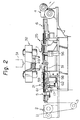
- a pair of stringers 1 are fed from a roll-shaped supply source (not shown) through a pair of guide rollers 2 and a tension roller 3 (see Fig. 2) in a state wherein the stringers 1 are combined together by the engagement between their respective fastener element trains 14.
- the stringers 1 are intermittently advanced by two rollers which in combination constitute a conveyor device 4.
- the fastener manufacturing apparatus has a stringer separating device 5 on the upstream side and a stringer re-combining device 6 on the downstream side.
- the apparatus further has an injection molding station 7 located between the devices 5 and 6.
- the stringer separating device 5 has a wedge member 9 which is disposed in such a manner that the pair of stringers 1, as they are advanced, are split into two by the wedge member 9.
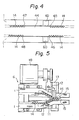
- the stringer re-combining device 6 has an inner guide member 11 and outer guide members 12 (see Fig. 5).
- the inner guide member 11 has a tapered distal end, while the outer guide members 12 are disposed in such a manner that they guide the fastener element trains 14 along the tapered distal end of the inner guide member 11.
- the arrangement is such that, as the respective fastener element trains 14 of the stringers 1 are passed through the area between these guide members, the fastener element trains 14 are re-engaged with each other.
- the terminating end of one of the outer guide members 12 is constituted by a movable guide member 13 which is pressed by the action of a spring (not shown) toward the fastener element trains 14 in such a manner that they are re-engaged with each other.
- the movable guide member 13 is movable upwardly as viewed in Fig. 5 by being pushed by upper stops 15 which are molded in a step, such as that which will be explained later, whereby the movable guide member 13 permits passage of the upper stops 15.
- the stringer separating device 5 is movable in the moving direction of the stringers 1 by the action of an air cylinder 17 (see Fig. 2).
- the stringer re-combining device 6 is similarly movable in the direction parallel with the moving direction of the stringers 1 by the action of an air cylinder 18 (see Fig. 1).
- a stringer guide device 21 is provided between the stringer separating device 5 and the injection molding station 7.
- the device 21, as shown in Fig. 3, has a guide plate 23 which is formed with fastener element guide passages 22, and a stringer holder 24 which covers the respective upper surfaces of the fastener element trains 14 within the guide passages 22.
- the guide plate 23 and the stringer holder 24 are vertically movable as one unit in such a manner that the unit is capable of selectively taking an upper conveying position and a lower injection molding position.
- a stringer guide device 25 (see Fig. 1) is similarly provided between the injection molding station 7 and the stringer re-combining device 6.
- the guide device 25 has guide plates 27 which are respectively formed with fastener element guide passages 26, and stringer holders 28.
- the guide plates 27 and the stringer holders 28 perform the same actions as those of the corresponding members which constitute the guide device 21.
- the members which constitute the guide device 25 are, however, laterally separated for the purpose of accommodating a runner removing device, described later, in the space defined therebetween.
- the injection molding station 7 includes a lower die 31 and an upper die 32 (see Fig. 2).
- the lower die 31 has cavities 36, 37, 39 and a runner 40 which communicates with these cavities.
- the cavities 36, 37 are provided for respectively forming pins 34, 35 (see Fig. 7) which constitute a separable end stop, while the cavities 39 are provided for respectively forming upper stops 15 (see Fig. 7).
- the lower die 31 further has fastener element guide passages 41 which respectively communicate with their associated cavities.
- the guide passages 41 are located at the same height as that of the guide passages 22 and 26 at the time when the guide plates 23 and 27 are at the injection molding position, that is, the lower position.
- the cavities 36, 37, 39 have stoppers 42, 43 which are respectively formed close to their outer ends.
- the stoppers 42, 43 effect positioning of the stringers 1 in such a manner that, when a portion of each of the tapes which respectively constitute the stringers 1 is bent at a space portion 44 (see Fig. 4) as described later, the stoppers 42, 43 respectively engage with end fastener elements 45, 46, 47, 48 at opposite ends of the space portion 44 such as to prevent these elements from moving toward the center of the injection molding station 7 and thereby effecting positioning of the stringers 1.
- These stoppers may be arranged in any desired form, provided that they are immovable relative to the injection molding station 7 in terms of the moving direction of the stringers 1.
- the upper die 32 is also provided with cavities and a runner for forming the pins and the upper stops in such a manner that the cavities and the runner respectively correspond to those of the lower die 31.
- the upper die 32 further has a sprue 49 which is formed such as to communicate with its runner.
- the sprue 49 is communicable with a nozzle 51 of an injection molding machine.
- the lower die 31 is further provided with recesses 52 in its center in such a manner that arms 53, 54 can be lowered into the'respective recesses 52.
- the arms 53, 54 are respectively connected to air cylinders 55, 56 in such a manner that the arms 53, 54 are vertically movable by the actions of the associated air cylinders,..$5, 56.
- the guide device 21 is provided at a portion thereof with a space sensor 58 which constitutes a part of a stringer positioning device.
- the space sensor 58 has a sensor lever 59, a spring 61 and a microswitch 62.
- the sensor lever 59 has sensor end portions 50 (see Fig. 3) which respectively project into the fastener element guide passages 22 respectively formed in the guide plate 23.
- the spring 61 is disposed such as to bias the sensor lever 59 in the direction in which its sensor end portions 50 respectively project into the guide passages 22.
- the microswitch 62 detects displacement of the sensor lever 59 which occurs when it is disengaged from the fastener element trains 14.
- the pair of interengaged fastener stringers 1 which have been fed through the pair of guide rollers 2 and the tension roller 3 are separated from each other by the wedge member 9 and are then fed to the injection molding station 7 while their respective fastener element trains 14 are being guided by the corresponding fastener element guide passages 22 in the stringer guide device 21.
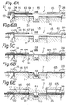
- the space portion 44, in which there are no fastener elements 14 reaches the position of the sensor end portions 50 of the sensor lever 59 constituting a part of the space sensor 58, the sensor lever 59 pivots in such a manner as to cause the microswitch 62 to generate a space sensing signal (see Fig. 6A).
- This signal actuates a timer device or distance measuring device of desired type (not shown) in such a manner that the conveyor device 4 is suspended after a predetermined period of time has elapsed from the time when the space portion 44 has been sensed, or after the stringers 1 have been moved over a predetermined distance.
- the space portion 44 is positioned in the center of the injection molding station 7 (see Fig. 6B).
- the stringer holders 24, 28 lower together with the associated guide plates 23, 27 until the respective fastener element guide passages 22, 26 become equal in height to the corresponding fastener element guide passages 41 of the lower die 41.
- the stringer holders 24, 28 are respectively provided with extended portions 64, 65 which press the corresponding fastener element trains 14 against the associated fastener element passages 22, 27 (see Fig. 6C).
- Each of the rollers constituting the conveyor device 4 is arranged such as to become reversible when it is released from the driving force applied thereto. Accordingly, under this state, the portion of each of the stringers 1 which is on the downstream side of the injection molding station 7 is able to return to the injection molding station 7.
- each of the stringers 1 on the upstream side of the injection molding station 7 is able to move toward the injection molding station 7 by the upward movement of the tension roller 3. Then, the air cylinders 17, 18 are actuated such as to move the stringer separating and re-combining devices 5, 6, respectively, toward the injection molding station 7, whereby it is possible for the stringers 1 to be drawn toward the injection molding station 7.
- the air cylinders 55, 56 are actuated such as to lower the arms 53, 54, respectively, thus causing a portion of each of the stringers 1 to be bent independently.
- the stringers 1 are drawn toward the center of the injection molding station 7 until the end fastener elements 45, 46, 47, 48 at the opposite ends of each space portion 44 are respectively retained by the associated stoppers 42, 43 of the lower die 31 (see Fig. 6D).
- each of the air cylinders 55, 56 is set to be large enough to ensure that the movement of the stringers 1 is not terminated before the fastener elements 45, 46, 47, 48 are properly retained by the associated stoppers 42, 43, thereby allowing a proper degree of push- down force to act on the arms 53, 54 even after the above-described fastener elements have been retained by the associated stoppers.
- the upper die 32 is lowered in such a manner that the upper and lower dies 32, 31 are clamped together (see Fig. 6E), thereby injection-molding pins 34, 35, which constitute a separable end stop, on pieces 60 of reinforcing tape which have previously been attached on the respective stringers 1 by a known method.
- upper stops 38 are injection-molded on the respective stringers 1 on the other side of the space portion 44.
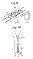
- the arrangement may be such that the degree of adhering strength between a runner 67 produced as a result of molding, the pins 34, 35 and the upper stops 38 is selected beforehand so that, when the stringers 1 which have been drawn toward the injection molding station 7 are stretched at the time of restarting the feeding operation of the conveyor device 4, the runner 67 comes off the upper stops 38 while maintaining its adherence to the pins 34, 35.
- the arrangement may be such that the runner 67 comes off the upper stops 38 while its adherence to the pins 34, 35 is maintained when the stringers 1 which have been drawn toward the injection molding station 7 are stretched by effectively varying the timing at iich the upper die 32 and the guide devices 21, 25 start tc. return to their previous positions (see Fig. 7).
- the runner 67 may be removed by any desired method.
- runner cutting edges 68 are provided in such a manner that they are selectively plunged into the area between the stringers 1 on the downstream side of the injection molding station 7 by the action of an air cylinder 69.
- the stringers 1 are fed to the stringer re-combining device 6 where they are re-engaged with each other.
- the stringers 1 re-combined together as described above are fed out from the conveyor device 44 and are then equipped with a slider 71 as shown in Fig. 10 by a known method.
- the re-combined stringers 1 are then cut at the space portion 4 and equipped with a box 72 which is secured to one (a box pin) of the pins 34, 35, thus becoming a complete slide fastener with a separable end stop.
Landscapes
- Slide Fasteners (AREA)
- Moulds For Moulding Plastics Or The Like (AREA)
- Injection Moulding Of Plastics Or The Like (AREA)
Applications Claiming Priority (2)
| Application Number | Priority Date | Filing Date | Title |
|---|---|---|---|
| JP93278/84 | 1984-05-10 | ||
| JP59093278A JPS60236602A (ja) | 1984-05-10 | 1984-05-10 | 開離嵌挿装置付スライドファスナの製造装置 |
Publications (3)
| Publication Number | Publication Date |
|---|---|
| EP0160983A2 true EP0160983A2 (fr) | 1985-11-13 |
| EP0160983A3 EP0160983A3 (en) | 1988-09-14 |
| EP0160983B1 EP0160983B1 (fr) | 1990-11-07 |
Family
ID=14077967
Family Applications (1)
| Application Number | Title | Priority Date | Filing Date |
|---|---|---|---|
| EP85105638A Expired - Lifetime EP0160983B1 (fr) | 1984-05-10 | 1985-05-08 | Méthode et appareil pour fabriquer des fermetures à glissière munies de butées d'extrémité séparables |
Country Status (13)
| Country | Link |
|---|---|
| US (1) | US4627807A (fr) |
| EP (1) | EP0160983B1 (fr) |
| JP (1) | JPS60236602A (fr) |
| KR (1) | KR860001941B1 (fr) |
| AU (1) | AU566083B2 (fr) |
| BR (1) | BR8502315A (fr) |
| CA (1) | CA1234280A (fr) |
| DE (1) | DE3580389D1 (fr) |
| ES (1) | ES8605192A1 (fr) |
| GB (1) | GB2158875B (fr) |
| HK (1) | HK51889A (fr) |
| MY (1) | MY100679A (fr) |
| SG (1) | SG25089G (fr) |
Cited By (3)
| Publication number | Priority date | Publication date | Assignee | Title |
|---|---|---|---|---|
| EP0612487A1 (fr) * | 1993-02-26 | 1994-08-31 | Ykk Corporation | Méthode pour mouler une butée d'éxtrémité séparable sur une fermeture à glissière du type masquée |
| EP0649611A1 (fr) * | 1993-10-20 | 1995-04-26 | Ykk Corporation | Procédé pour mouler des arrêts en bout sur une chaîne de fermeture à glissière et dispositif de séparation de chaîne utilisé à cette fin |
| CN101773318B (zh) * | 2010-01-14 | 2012-01-25 | 施天程 | 一种合金拉链链齿的制作方法 |
Families Citing this family (8)
| Publication number | Priority date | Publication date | Assignee | Title |
|---|---|---|---|---|
| JPS60180514U (ja) * | 1984-05-10 | 1985-11-30 | ワイケイケイ株式会社 | フアスナストリンガの組合せ装置 |
| MY101685A (en) * | 1986-10-28 | 1991-12-31 | Yoshida Kogyo Kk | Apparatus for manufacturing slide fasteners |
| JPS63125203A (ja) * | 1986-11-14 | 1988-05-28 | ワイケイケイ株式会社 | スライドフアスナ−製造装置 |
| DE3880134D1 (de) * | 1988-07-15 | 1993-05-13 | Opti Patent Forschung Fab | Verfahren und vorrichtung zur herstellung von reissverschluessen. |
| KR100414993B1 (ko) * | 1996-01-22 | 2004-08-25 | 삼도물산 주식회사 | 슬라이드파스너의상지구와하지구를동시에성형하는장치 |
| CA2364508A1 (fr) * | 1999-03-09 | 2000-09-14 | Thomas Skorch | Procede et dispositif facilitant la depose d'entrees d'un moule |
| CN104703771B (zh) * | 2014-01-14 | 2017-04-12 | Ykk株式会社 | 止挡构件成形装置 |
| CN104968233B (zh) * | 2014-03-25 | 2017-09-15 | Ykk株式会社 | 反开式拉链的制造方法及制造装置 |
Citations (7)
| Publication number | Priority date | Publication date | Assignee | Title |
|---|---|---|---|---|
| GB713108A (en) * | 1950-12-14 | 1954-08-04 | Ri Ri Werk A G | Improved method and means for making slide fasteners |
| US2849753A (en) * | 1953-08-13 | 1958-09-02 | Ri Ri Werke A G | Apparatus for the manufacture of sliding clasp fasteners |
| FR2338667A1 (fr) * | 1976-01-22 | 1977-08-19 | Interbrev Sa | Procede de fabrication de fermetures a glissiere separables et dispositif pour la mise en oeuvre du procede |
| FR2344243A1 (fr) * | 1976-03-18 | 1977-10-14 | Horlacher Hans | Procede et dispositif pour fabriquer des fermetures a glissiere |
| FR2401758A1 (fr) * | 1977-09-15 | 1979-03-30 | Horlacher Hans | Dispositif de positionnement des galons de fermetures a glissiere dans un moule de fabrication de telles fermetures |
| GB2088469A (en) * | 1980-11-27 | 1982-06-09 | Yoshida Kogyo Kk | Attaching top and bottom stops to a slide fastener chain |
| EP0089002A2 (fr) * | 1982-03-17 | 1983-09-21 | Yoshida Kogyo K.K. | Méthode et appareil pour fixer automatiquement des butées d'extrémité supérieures sur une chaîne de fermeture à glissière munie d'intervalles dépourvus d'éléments d'accouplement et sur laquelle sont montés des curseurs |
Family Cites Families (10)
| Publication number | Priority date | Publication date | Assignee | Title |
|---|---|---|---|---|
| US3097395A (en) * | 1963-07-16 | Tadao yoshida | ||
| US2543111A (en) * | 1947-05-14 | 1951-02-27 | Conmar Prod Corp | Apparatus for molding plastic slide fasteners |
| US2705814A (en) * | 1950-12-14 | 1955-04-12 | Ri Ri Werk A G | Manufacture of slide fasteners |
| US2686338A (en) * | 1952-03-08 | 1954-08-17 | Louis H Morin | Machine for producing reinforced plastic scoop stringers |
| ATA712170A (de) * | 1970-08-05 | 1975-10-15 | Anderegg Hans | Tragbandvorschubeinrichtung an spritzgussmaschinen zur herstellung von reissverschlussen |
| FI52535C (fi) * | 1975-03-05 | 1977-10-10 | Stenhaell Oy Turo | Vetoketjun valmistusmenetelmä ja -laite |
| US4034445A (en) * | 1975-07-28 | 1977-07-12 | Textron, Inc. | Molded top stop and apparatus and method of manufacture |
| JPS6027608Y2 (ja) * | 1978-07-04 | 1985-08-21 | ワイケイケイ株式会社 | 連続スライドフアスナ−チエ−ン射出成形用金型 |
| JPS5651326A (en) * | 1979-10-01 | 1981-05-08 | Yoshida Kogyo Kk <Ykk> | Method and apparatus for manufacturing slide fastener with synthetic resin zipper |
| JPS5991906A (ja) * | 1982-11-19 | 1984-05-26 | ワイケイケイ株式会社 | 合成樹脂製務歯を有するスライドフアスナ−チエンの製造装置 |
-
1984
- 1984-05-10 JP JP59093278A patent/JPS60236602A/ja active Granted
-
1985
- 1985-04-05 US US06/720,419 patent/US4627807A/en not_active Expired - Fee Related
- 1985-04-09 CA CA000478532A patent/CA1234280A/fr not_active Expired
- 1985-04-12 AU AU41079/85A patent/AU566083B2/en not_active Ceased
- 1985-04-29 ES ES542656A patent/ES8605192A1/es not_active Expired
- 1985-05-08 KR KR1019850003120A patent/KR860001941B1/ko not_active IP Right Cessation
- 1985-05-08 EP EP85105638A patent/EP0160983B1/fr not_active Expired - Lifetime
- 1985-05-08 DE DE8585105638T patent/DE3580389D1/de not_active Expired - Lifetime
- 1985-05-08 GB GB08511635A patent/GB2158875B/en not_active Expired
- 1985-05-10 BR BR8502315A patent/BR8502315A/pt not_active IP Right Cessation
-
1987
- 1987-08-07 MY MYPI87001237A patent/MY100679A/en unknown
-
1989
- 1989-04-13 SG SG250/89A patent/SG25089G/en unknown
- 1989-06-29 HK HK518/89A patent/HK51889A/xx not_active IP Right Cessation
Patent Citations (7)
| Publication number | Priority date | Publication date | Assignee | Title |
|---|---|---|---|---|
| GB713108A (en) * | 1950-12-14 | 1954-08-04 | Ri Ri Werk A G | Improved method and means for making slide fasteners |
| US2849753A (en) * | 1953-08-13 | 1958-09-02 | Ri Ri Werke A G | Apparatus for the manufacture of sliding clasp fasteners |
| FR2338667A1 (fr) * | 1976-01-22 | 1977-08-19 | Interbrev Sa | Procede de fabrication de fermetures a glissiere separables et dispositif pour la mise en oeuvre du procede |
| FR2344243A1 (fr) * | 1976-03-18 | 1977-10-14 | Horlacher Hans | Procede et dispositif pour fabriquer des fermetures a glissiere |
| FR2401758A1 (fr) * | 1977-09-15 | 1979-03-30 | Horlacher Hans | Dispositif de positionnement des galons de fermetures a glissiere dans un moule de fabrication de telles fermetures |
| GB2088469A (en) * | 1980-11-27 | 1982-06-09 | Yoshida Kogyo Kk | Attaching top and bottom stops to a slide fastener chain |
| EP0089002A2 (fr) * | 1982-03-17 | 1983-09-21 | Yoshida Kogyo K.K. | Méthode et appareil pour fixer automatiquement des butées d'extrémité supérieures sur une chaîne de fermeture à glissière munie d'intervalles dépourvus d'éléments d'accouplement et sur laquelle sont montés des curseurs |
Cited By (5)
| Publication number | Priority date | Publication date | Assignee | Title |
|---|---|---|---|---|
| EP0612487A1 (fr) * | 1993-02-26 | 1994-08-31 | Ykk Corporation | Méthode pour mouler une butée d'éxtrémité séparable sur une fermeture à glissière du type masquée |
| US5470516A (en) * | 1993-02-26 | 1995-11-28 | Yoshida Kogyo K.K. | Method of molding a separable bottom stop assembly on a concealed slide fastener |
| EP0649611A1 (fr) * | 1993-10-20 | 1995-04-26 | Ykk Corporation | Procédé pour mouler des arrêts en bout sur une chaîne de fermeture à glissière et dispositif de séparation de chaîne utilisé à cette fin |
| US5536460A (en) * | 1993-10-20 | 1996-07-16 | Ykk Corporation | Method of forming end stops molded on a slide fastener chain and a chain splitting apparatus used therein |
| CN101773318B (zh) * | 2010-01-14 | 2012-01-25 | 施天程 | 一种合金拉链链齿的制作方法 |
Also Published As
| Publication number | Publication date |
|---|---|
| GB8511635D0 (en) | 1985-06-12 |
| SG25089G (en) | 1989-07-14 |
| KR850008611A (ko) | 1985-12-21 |
| ES8605192A1 (es) | 1986-04-01 |
| CA1234280A (fr) | 1988-03-22 |
| DE3580389D1 (de) | 1990-12-13 |
| EP0160983A3 (en) | 1988-09-14 |
| HK51889A (en) | 1989-07-07 |
| BR8502315A (pt) | 1986-01-21 |
| GB2158875B (en) | 1987-11-18 |
| EP0160983B1 (fr) | 1990-11-07 |
| US4627807A (en) | 1986-12-09 |
| ES542656A0 (es) | 1986-04-01 |
| KR860001941B1 (ko) | 1986-11-01 |
| JPS60236602A (ja) | 1985-11-25 |
| AU4107985A (en) | 1985-11-14 |
| MY100679A (en) | 1991-01-17 |
| JPH0128564B2 (fr) | 1989-06-05 |
| AU566083B2 (en) | 1987-10-08 |
| GB2158875A (en) | 1985-11-20 |
Similar Documents
| Publication | Publication Date | Title |
|---|---|---|
| KR970000802B1 (ko) | 분리형 하단 정지부재를 갖는 지퍼체인의 제조방법 및 장치 | |
| US4627807A (en) | Apparatus for manufacturing slide fastener with separable end stop | |
| KR840002315B1 (ko) | 슬라이드 파스너 체인의 개리감삽구 부착부분에 대한 보강대 부착방법 및 장치 | |
| EP0099064B1 (fr) | Procédé et appareil pour fixer une butée d'arrêt inférieure séparable à une paire de rubans d'une fermeture à glissière | |
| EP0396373B1 (fr) | Méthode et appareil pour fixer des butées d'extrémité supérieures sur une chaîne de fermetures à glissière | |
| JP3423479B2 (ja) | スライドファスナーチェーンのスペース部におけるファスナーエレメント除去方法及びその装置 | |
| EP0145016A2 (fr) | Appareil pour former par fusion les butées d'extrémité inférieures d'une chaîne de fermetures à glissière | |
| EP0160932B1 (fr) | Appareil pour accoupler des rubans de bandes de fermeture à glissière | |
| EP0068317B1 (fr) | Procédé et dispositif pour la fixation de matériau de renforcement sur bandes de fermetures éclair | |
| KR960014741B1 (ko) | 슬라이드 파스너 체인 위에 몰드된 단부 정지구들을 형성하는 방법과 그에 사용된 체인 분할 장치 | |
| EP0099065B1 (fr) | Dispositif de fabrication de fermetures à glissière séparables | |
| JP4046726B2 (ja) | インサート成形装置、インサート成形用端子材およびインサート成形方法 | |
| KR820000019B1 (ko) | 슬라이드 파스너의 제조방법 | |
| JPH0226657Y2 (fr) | ||
| JPS61171317A (ja) | 2重成形方法 | |
| JPH0360653B2 (fr) | ||
| TH7106B (th) | วิธีการและเครื่องสำหรับการผลิตลูกโซ่ซิปแบบเลื่อนพร้อมด้วยชิ้นส่วนตัวหยุดส่วนปลายด้านล่างที่สามารถแยกออกได้ | |
| TH20984A (th) | วิธีการและเครื่องสำหรับการผลิตลูกโซ่ซิปแบบเลื่อนพร้อมด้วยชิ้นส่วนตัวหยุดส่วนปลายด้านล่างที่สามารถแยกออกได้ | |
| JPH01118424A (ja) | 部品集合体の製造装置 |
Legal Events
| Date | Code | Title | Description |
|---|---|---|---|
| PUAI | Public reference made under article 153(3) epc to a published international application that has entered the european phase |
Free format text: ORIGINAL CODE: 0009012 |
|
| AK | Designated contracting states |
Designated state(s): BE DE FR IT NL |
|
| PUAL | Search report despatched |
Free format text: ORIGINAL CODE: 0009013 |
|
| AK | Designated contracting states |
Kind code of ref document: A3 Designated state(s): BE DE FR IT NL |
|
| 17P | Request for examination filed |
Effective date: 19881202 |
|
| 17Q | First examination report despatched |
Effective date: 19900109 |
|
| GRAA | (expected) grant |
Free format text: ORIGINAL CODE: 0009210 |
|
| AK | Designated contracting states |
Kind code of ref document: B1 Designated state(s): BE DE FR IT NL |
|
| ITF | It: translation for a ep patent filed | ||
| ET | Fr: translation filed | ||
| REF | Corresponds to: |
Ref document number: 3580389 Country of ref document: DE Date of ref document: 19901213 |
|
| PLBE | No opposition filed within time limit |
Free format text: ORIGINAL CODE: 0009261 |
|
| STAA | Information on the status of an ep patent application or granted ep patent |
Free format text: STATUS: NO OPPOSITION FILED WITHIN TIME LIMIT |
|
| 26N | No opposition filed | ||
| ITTA | It: last paid annual fee | ||
| PGFP | Annual fee paid to national office [announced via postgrant information from national office to epo] |
Ref country code: BE Payment date: 19940222 Year of fee payment: 10 |
|
| PGFP | Annual fee paid to national office [announced via postgrant information from national office to epo] |
Ref country code: FR Payment date: 19940420 Year of fee payment: 10 |
|
| PGFP | Annual fee paid to national office [announced via postgrant information from national office to epo] |
Ref country code: NL Payment date: 19940531 Year of fee payment: 10 |
|
| ITPR | It: changes in ownership of a european patent |
Owner name: CAMBIO RAGIONE SOCIALE;YKK CORPORATION |
|
| REG | Reference to a national code |
Ref country code: FR Ref legal event code: CD |
|
| PG25 | Lapsed in a contracting state [announced via postgrant information from national office to epo] |
Ref country code: BE Effective date: 19950531 |
|
| BERE | Be: lapsed |
Owner name: YKK CORP. Effective date: 19950531 |
|
| PG25 | Lapsed in a contracting state [announced via postgrant information from national office to epo] |
Ref country code: NL Effective date: 19951201 |
|
| NLV4 | Nl: lapsed or anulled due to non-payment of the annual fee |
Effective date: 19951201 |
|
| PG25 | Lapsed in a contracting state [announced via postgrant information from national office to epo] |
Ref country code: FR Effective date: 19960229 |
|
| REG | Reference to a national code |
Ref country code: FR Ref legal event code: ST |
|
| REG | Reference to a national code |
Ref country code: FR Ref legal event code: ST |
|
| PGFP | Annual fee paid to national office [announced via postgrant information from national office to epo] |
Ref country code: DE Payment date: 20040520 Year of fee payment: 20 |