EP0160707B1 - Dispositif de déplacement rotatif pas à pas piézo-électrique - Google Patents
Dispositif de déplacement rotatif pas à pas piézo-électrique Download PDFInfo
- Publication number
- EP0160707B1 EP0160707B1 EP84104926A EP84104926A EP0160707B1 EP 0160707 B1 EP0160707 B1 EP 0160707B1 EP 84104926 A EP84104926 A EP 84104926A EP 84104926 A EP84104926 A EP 84104926A EP 0160707 B1 EP0160707 B1 EP 0160707B1
- Authority
- EP
- European Patent Office
- Prior art keywords
- rotator
- piezoelectric
- shoe
- clamping
- pair
- Prior art date
- Legal status (The legal status is an assumption and is not a legal conclusion. Google has not performed a legal analysis and makes no representation as to the accuracy of the status listed.)
- Expired
Links
- 238000003462 Bender reaction Methods 0.000 claims description 9
- 241001125879 Gobio Species 0.000 claims description 6
- 239000002184 metal Substances 0.000 claims description 4
- 230000000284 resting effect Effects 0.000 claims description 2
- 238000006073 displacement reaction Methods 0.000 description 10
- 238000005452 bending Methods 0.000 description 5
- 238000010586 diagram Methods 0.000 description 4
- 238000004519 manufacturing process Methods 0.000 description 4
- 230000008602 contraction Effects 0.000 description 2
- 230000005641 tunneling Effects 0.000 description 2
- 238000011109 contamination Methods 0.000 description 1
- 239000000428 dust Substances 0.000 description 1
- 230000005684 electric field Effects 0.000 description 1
- 230000007613 environmental effect Effects 0.000 description 1
- 238000007689 inspection Methods 0.000 description 1
- 238000011835 investigation Methods 0.000 description 1
- 238000000034 method Methods 0.000 description 1
Images

Classifications
-
- B—PERFORMING OPERATIONS; TRANSPORTING
- B82—NANOTECHNOLOGY
- B82Y—SPECIFIC USES OR APPLICATIONS OF NANOSTRUCTURES; MEASUREMENT OR ANALYSIS OF NANOSTRUCTURES; MANUFACTURE OR TREATMENT OF NANOSTRUCTURES
- B82Y15/00—Nanotechnology for interacting, sensing or actuating, e.g. quantum dots as markers in protein assays or molecular motors
-
- H—ELECTRICITY
- H02—GENERATION; CONVERSION OR DISTRIBUTION OF ELECTRIC POWER
- H02N—ELECTRIC MACHINES NOT OTHERWISE PROVIDED FOR
- H02N2/00—Electric machines in general using piezoelectric effect, electrostriction or magnetostriction
- H02N2/10—Electric machines in general using piezoelectric effect, electrostriction or magnetostriction producing rotary motion, e.g. rotary motors
- H02N2/101—Electric machines in general using piezoelectric effect, electrostriction or magnetostriction producing rotary motion, e.g. rotary motors using intermittent driving, e.g. step motors
Definitions
- the present invention relates to piezoelectric stepping rotators permitting circular displacements with seconds of arc precision, for use in surface science and micro-manufacturing applications.
- the positioners used in these applications must be vacuum- compatible and be able to resist baking up to about 500 K. Also, to be able to resolve features down to the atomic level, the positioners used must be free of vibrations to a.very high degree, i.e. they have to be mechanically decoupled from the outside world. These requirements can be met by positioners working with piezoelectric elements which are controlled through electrical potentials applied to their electrodes.
- piezoelectric positioners which permit longitudinal translation of an object, such as the one shown in IBM Technical Disclosure Bulletin, Vol. 22, No. 7, p. 2897 where a H-shaped piezoelectric member can move in a trough-like channel by alternatively clamping pairs of legs against the channel walls and contracting pairs of legs against the channel walls and contracting and expanding its center portion.
- a H-shaped piezoelectric member can move in a trough-like channel by alternatively clamping pairs of legs against the channel walls and contracting pairs of legs against the channel walls and contracting and expanding its center portion.
- the straight channel permits only linear motion.
- piezoelectric positioners which avoid the channel in favor of greater flexibility of movement. They use a table-like configuration, as shown in IBM Technical Disclosure Bulletin, Vol, 23, No. 7B, p. 3369, where the table rests on eight piezoelectric legs, four of which are connected to an inner section of the table, the others to its outer section, the sections being linked by piezoelectric elements. By controlled lifting and lowering the said groups of legs and through appropriate extension and contraction of the linking elements, the table can be moved in orthogonal directions.
- a piezoelectric stepping rotator comprising a stator and a rotor is known with clamping means controllable to be effective between stator and rotor, wherein at least one piezoelectric bender (a unimorph) is provided with one end pivotally supported and with its other end carrying a clamping element, viz. an electromagnet.
- Still another type of stepping motor is disclosed in IBM Technical Disclosure Bulletin, Vol. 16, No. 6, p. 1899.
- the periphery of a capstan is engaged radially by a piezoelectrically driven rod which in turn is movable tangentially by a piezoelectric transducer.
- This motor permits the capstan to perform small rotary steps, suitable for a tape drive as shown, but in no way accurate or reproducible in the sense of scientific or manufacturing applications.
- an object of the present invention to propose a piezoelectric rotator which meets the environmental requirements outlined above (viz. ultra-high vacuum, temperature resistance, vibration-free) and which permits position-independent displacements along a circular path, even in the form of continuous rotation, with a resolution (accuracy) in the order of nanometers.
- a piezoelectric stepping rotator comprising a stator and a rotor and clamping means controllable to be effective between stator and rotor, at least one first piezoelectric bender with one end pivotally supported and at its other end carrying a clampable shoe, and at least one pair of second piezoelectric benders each connected to at least one clamping member and controllable to arrest said clampable shoe when said first piezoelectric bender has assumed its bent state, and to release said clampable shoe after said first bender has stretched.
- said first piezoelectric bender is with one end mounted to a pivotable shaft and carries at its other end a block fitted with a piezoelectric clamping member in the form of a rod or tube controllable to be brought into and out of engagement with housing halves in a bearing of which said shaft is supported.
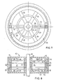
- Fig. 1 shows a first embodiment of the rotator mounted on a base plate 1.
- a block 3 Pivotally mounted between gudgeons 2 is a block 3 which supports a piezoelectric bender, commonly called bimorph 4, with its electrodes supplied with a potential such that when actuated bimorph 4 will lift its righthand end (in Fig. 1) out of the plane of the paper.
- Block 3 is equipped with an adjustable screw 5 which serves to counterbalance the masses of bimorph 4, of the clamping shoe 6 attached to the free end of bimorph 4, as well as of the "payload" 7 carried by clamping shoe 6.
- Payload 7 can, for example, be an object which has to be moved for inspection, or treatment, or a tool or electrode, such as the tip of a Scanning Tunneling Microscope.
- Gudgeons 2 are supported in angles 8 and 9 resting on base plate 1.
- Fig. 2 shows a side view of this arrangement.
- a pair of bimorphs 10 and 11 rests in supports 12 and 13, respectively, which are fixed on base plate 1.
- Bimorphs 10 and 11 extend all along the length of bimorph 4 including clamping shoe 6 and block 3. (Bimorphs 10 and 11 may also be realized by two shorter bimorphs each.)
- Bimorphs 10 and 11 at their ends carry clamping members 14, 15 and 16, 17, respectively. With no potential applied to the electrodes of bimorphs 10 and 11, clamping members 14 and 16 will rest against block 3 and clamping members 15 and 17 will rest against clamping shoe 6.
- Fig. 1 shows the state where a potential has been applied to the righthand halves of bimorphs 10 and 11 causing clamping members 15 and 17 to clear clamping shoe 6. With a potential applied, bimorph 4 will bend upwardly (Fig. 3) raising payload 7 along a circular path above its home position.
- the amount of bending excercised by the various bimorphs strictly depends on the amplitude of the potential applied. It is, accordingly possible to lift payload 7 through fractions of a second of arc in one step of the procedure just described, which can, of course be repeated until the desired deflection has been reached.
- the bender can, of course, be caused to perform larger steps by applying greater amplitudes.
- a bender 25 mm long, for example, can move about 1 um/V, corresponding to approximately 10 seconds of arc per volt, in the arrangement of Figs. 1 through 5.
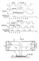
- Fig. 6 is a timing diagram illustrating in a schematic fashion the sequence of steps occuring during the operation of the embodiment of Figs. 1 through 5.
- potentials U 1 and U 2 at the electrodes of bimorphs 10 and 11 are zero so that block 3 and shoe 6 are being clamped.
- clamping members 15 and 17 open, permitting bimorph 4 to bend when U 3 is applied at time t 2 .
- Payload 7 thus performs a first rotary step between times t 2 and t 3 .
- U 1 is switched off so that payload 7 is arrested in its attained position.
- payload 7 can be caused to return to its original position by versing the potential U 3 at bimorph 4 and applying potentials U 1 and U 3 at bimorphs 10 and 11 in the opposite sequence.
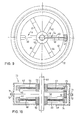
- FIGs. 7 and 8 depict a piezoelectric rotator designed for unlimited rotation.
- This embodiment can be thought of as being derived from the one shown in Figs. 1 through 5 with gudgeons 2 replaced by a shaft 18, and clamping member 14 through 17 replaced by two pairs of clamping rings 19, 20 and 21, 22.
- bimorph 24 Fixed to a hub 23 rigidly attached to shaft 18 is bimorph 24 the free end of which carries a clamping shoe 25.
- the rings 21 and 22 are arranged idling on shaft 18, each carrying a plurality (for example: six) spoke-like bimorphs 26 through 31 and 32 through 37, respectively.
- Bimorphs 26 through 31 extend between rings 19 and 21, whereas bimorphs 32 through 37 extend between rings 20 and 22.
- Each of the bimorphs 26 through 37 is mounted at its center to a circular rib 38, 39 forming an integral part with the lower and upper halves'40 and 41, respectively, of a housing 42.
- Ribs 38 and 39 are analogues to supports 12 and 13 of the embodiment shown in Figs. 1 through 5.
- the electrodes of bimorphs 26 through 37 are split at the location of attachment to ribs 38 and 39 so that the two halves in each bimorph can be activated individually.
- Control of the bimorphs in this and the other embodiments described below is performed by suitable electronic circuitry not subject of this invention, and supply of the control potentials can be made via conventional sliding contact rings known in the art but not shown in the drawings.
- Rings 19 and 20 are held clear of shoe 25, whereas rings 21 and 22 clamp hub 23 between them.
- Application of a potential to the electrodes of bimorph 24 results in a bending of the latter which causes a slight circular displacement of shoe 25 with respect to rings 19 and 20.
- a potential is now applied to the partitioned electrodes of bimorphs 24 through 37 causing rings 19 and 20 to clamp shoe 25 between them and to release hub 23 from between rings 21 and 22. So far, no rotation of shaft 18 has occurred, but as the potential at bimorph 24 is switched off, the bimorph will stretch to a straight shape and at the same time rotating shaft 18 through one step with respect to housing 42. The cycle may now be repeated.
- bimophs 25 through 37 may be loosely supported in grooves 43 through 46 machined into rings 19 through 22 to avoid breaking.
- appropriate provision should be made to prevent mutual circular displacement between bimorphs and clamping rings.
- the rotator of Figs. 7 and-8 in operation generates a mutual rotary displacement between shaft 18 and housing 42.
- the man skilled in the art will understand that the torque may be obtained at the shaft or at the housing.
- FIGs. 9 and 10 A similar but simplified embodiment of a rotator for unlimited rotation is shown in Figs. 9 and 10.
- bimorph 50 Fixed to shaft 49 is bimorph 50 the free end of which carries a clamping shoe 51. Hubs 52 and 53 are arranged idling on shaft 49, each hub carrying a plurality (for example: six) spoke-like bimorphs 54 through 59 (only 54 and 57 are shown) and 60 through 65, respectively. Bimorphs 54 through 59 are fixed to a ring 66 whereas bimorphs 60 through 65 are connected to a ring 67.
- Hubs 52 and 53 are interconnected by means of two halves 68 and 69 of a casing 70 which are sealed to each other at their flanges 71,72 (Fig. 8).
- grooves 73 and 74 are provided on the inside of rings 66 and 67 to allow bimorphs 54 through 65 to change their length and slightly deflect without breaking.
- Figs. 9 and 10 show only a single piezoelectric bender or bimorph 50 for generating the torque for this positioner, obviously, a plurality of bimorphs with clamping shoes may be used in a concentric arrangement to increase the torque.
- the timing diagram of Fig. 11 shows that at time to clamping shoe 51 is arrested by rings 66 and 67.
- the potential U 4 applied to the electrodes of bimorph 50 causes the latter to bend and shaft 49 to rotate between t 1 and t 2 .
- U 5 is applied to bimorphs 54 through 65 removing rings 66 and 67 from shoe 51. Now potentials U 4 and U 5 are switched off so that bimorph 50 is allowed to stretch and rings 66 and 67 to clamp. At this point the cycle might be started afresh.
- Fig. 12 shows still another embodiment of the rotator in accordance with the invention in which the clamping of the bimorphs generating the rotation is done in a way different from that shown in Figs. 8 and 10.
- the rotor consisting of a shaft 75 and bimorphs 76, 77 is contained within housing halves 78 and 79 which may be screwed at their flanges 80 and 81.
- Bimorphs 76 and 77 carry blocks 82 and 83 at their free ends, the blocks being provided with piezoelectric rods or tubes 84 and 85, respectively.
- the length of rods 84, 85 is such that they normally rest with both ends against housing halves 78, 79 thus arresting blocks 82, 83 against displacement.
- a very simple arrangement for arresting shafts 18, 49, 75 is shown in connection with the rotator of Fig. 12. Attached to one end of shaft 75 is a metal disk 86 which is coated with a dielectric layer 87. Disk 86 is maintained at a minute distance above a metal plate 88. Application of a potential between disk 86 and plate 88 causes an electrical field and, hence, electrostatic forces which attract and fix disk 86 against rotation. The effectiveness of this arrangement can be increased considerably, and the tolerances softened through choosing a very thin, flexible sheet metal for disk 86. It will pose no problem for those skilled in the art to control this locking mechanism in coordination with the actuation of the various piezoelectric elements involved.
- Figs. 8, 10 and 12 can easily be made to rotate in both directions by just reversing the polarity of the potential applied to bimorphs 21; 45, 46 and by appropriately reversing the said locking mechanism.
Claims (11)
Priority Applications (5)
| Application Number | Priority Date | Filing Date | Title |
|---|---|---|---|
| EP84104926A EP0160707B1 (fr) | 1984-05-03 | 1984-05-03 | Dispositif de déplacement rotatif pas à pas piézo-électrique |
| DE8484104926T DE3474380D1 (en) | 1984-05-03 | 1984-05-03 | Piezoelectric stepping rotator |
| US06/655,271 US4600854A (en) | 1984-03-05 | 1984-09-28 | Piezoelectric stepping rotator |
| JP60005145A JPS60234477A (ja) | 1984-05-03 | 1985-01-17 | 圧電回転装置 |
| JP2037530A JPH0744857B2 (ja) | 1984-05-03 | 1990-02-20 | 圧電回転装置 |
Applications Claiming Priority (1)
| Application Number | Priority Date | Filing Date | Title |
|---|---|---|---|
| EP84104926A EP0160707B1 (fr) | 1984-05-03 | 1984-05-03 | Dispositif de déplacement rotatif pas à pas piézo-électrique |
Publications (2)
| Publication Number | Publication Date |
|---|---|
| EP0160707A1 EP0160707A1 (fr) | 1985-11-13 |
| EP0160707B1 true EP0160707B1 (fr) | 1988-09-28 |
Family
ID=8191914
Family Applications (1)
| Application Number | Title | Priority Date | Filing Date |
|---|---|---|---|
| EP84104926A Expired EP0160707B1 (fr) | 1984-03-05 | 1984-05-03 | Dispositif de déplacement rotatif pas à pas piézo-électrique |
Country Status (4)
| Country | Link |
|---|---|
| US (1) | US4600854A (fr) |
| EP (1) | EP0160707B1 (fr) |
| JP (2) | JPS60234477A (fr) |
| DE (1) | DE3474380D1 (fr) |
Cited By (1)
| Publication number | Priority date | Publication date | Assignee | Title |
|---|---|---|---|---|
| DE102008013782A1 (de) * | 2008-03-12 | 2009-06-25 | Robert Bosch Gmbh | Piezoelektrischer Biegewandler |
Families Citing this family (16)
| Publication number | Priority date | Publication date | Assignee | Title |
|---|---|---|---|---|
| JPS6162370A (ja) * | 1984-08-31 | 1986-03-31 | Tokyo Juki Ind Co Ltd | ピエゾモ−タ |
| US4734610A (en) * | 1986-03-25 | 1988-03-29 | Canon Kabushiki Kaisha | Vibration wave motor |
| US4890027A (en) * | 1988-11-21 | 1989-12-26 | Hughes Aircraft Company | Dynamic motor controller |
| US5247222A (en) * | 1991-11-04 | 1993-09-21 | Engle Craig D | Constrained shear mode modulator |
| US5631824A (en) * | 1994-05-26 | 1997-05-20 | Polytechnic University | Feedback control apparatus and method thereof for compensating for changes in structural frequencies |
| US5604413A (en) * | 1994-09-07 | 1997-02-18 | Polytechnic University | Apparatus for improving operational performance of a machine or device |
| US6154000A (en) * | 1994-09-07 | 2000-11-28 | Omnitek Research & Development, Inc. | Apparatus for providing a controlled deflection and/or actuator apparatus |
| JPH0947927A (ja) * | 1995-08-07 | 1997-02-18 | Toyota Motor Corp | 回転アクチュエータ及びそれを使用したネジ締め機 |
| US5945772A (en) * | 1998-05-29 | 1999-08-31 | Motorla, Inc. | Damped resonant piezoelectric alerting device |
| SE0004733D0 (sv) * | 2000-12-20 | 2000-12-20 | Piezomotor Uppsala Ab | Double bimorph electromechanical element |
| US6590208B2 (en) * | 2001-01-19 | 2003-07-08 | Veeco Instruments Inc. | Balanced momentum probe holder |
| GB0113350D0 (en) * | 2001-06-01 | 2001-07-25 | Pbt Ip Ltd | A rotary actuator mechanism |
| US7161580B2 (en) * | 2002-04-25 | 2007-01-09 | Immersion Corporation | Haptic feedback using rotary harmonic moving mass |
| US7369115B2 (en) * | 2002-04-25 | 2008-05-06 | Immersion Corporation | Haptic devices having multiple operational modes including at least one resonant mode |
| CN1913329B (zh) * | 2006-07-20 | 2010-11-10 | 清华大学 | 压电双晶片驱动的精密转动机构及其装置 |
| US8777179B2 (en) * | 2008-11-24 | 2014-07-15 | Hess Innovation Gmbh | Drive mechanism for the movement of an object along an axis of motion and micro-valve |
Family Cites Families (9)
| Publication number | Priority date | Publication date | Assignee | Title |
|---|---|---|---|---|
| GB1071648A (en) * | 1964-11-06 | 1967-06-07 | Standard Telephones Cables Ltd | Position control device |
| US3684904A (en) * | 1969-04-24 | 1972-08-15 | Gennady Vasilievich Galutva | Device for precision displacement of a solid body |
| JPS5112497B1 (fr) * | 1971-04-21 | 1976-04-20 | ||
| JPS5315060A (en) * | 1976-07-28 | 1978-02-10 | Hitachi Ltd | Inching device |
| SU604057A1 (ru) * | 1976-12-01 | 1978-04-25 | Предприятие П/Я Р-6324 | Пьезоэлектрический двигатель угловых перемещений |
| JPS5548832A (en) * | 1978-10-04 | 1980-04-08 | Matsushita Electric Ind Co Ltd | Magnetic recording and reproducing unit of rotary head type |
| DE3168777D1 (en) * | 1981-08-10 | 1985-03-21 | Ibm | Electric travelling support |
| US4435667A (en) * | 1982-04-28 | 1984-03-06 | Peizo Electric Products, Inc. | Spiral piezoelectric rotary actuator |
| JPS5976184A (ja) * | 1982-10-22 | 1984-05-01 | Hitachi Ltd | アクチユエ−タ |
-
1984
- 1984-05-03 DE DE8484104926T patent/DE3474380D1/de not_active Expired
- 1984-05-03 EP EP84104926A patent/EP0160707B1/fr not_active Expired
- 1984-09-28 US US06/655,271 patent/US4600854A/en not_active Expired - Lifetime
-
1985
- 1985-01-17 JP JP60005145A patent/JPS60234477A/ja active Granted
-
1990
- 1990-02-20 JP JP2037530A patent/JPH0744857B2/ja not_active Expired - Fee Related
Cited By (1)
| Publication number | Priority date | Publication date | Assignee | Title |
|---|---|---|---|---|
| DE102008013782A1 (de) * | 2008-03-12 | 2009-06-25 | Robert Bosch Gmbh | Piezoelektrischer Biegewandler |
Also Published As
| Publication number | Publication date |
|---|---|
| JPH0353874B2 (fr) | 1991-08-16 |
| DE3474380D1 (en) | 1988-11-03 |
| JPH0744857B2 (ja) | 1995-05-15 |
| EP0160707A1 (fr) | 1985-11-13 |
| JPH02262876A (ja) | 1990-10-25 |
| JPS60234477A (ja) | 1985-11-21 |
| US4600854A (en) | 1986-07-15 |
Similar Documents
| Publication | Publication Date | Title |
|---|---|---|
| EP0160707B1 (fr) | Dispositif de déplacement rotatif pas à pas piézo-électrique | |
| WO1988005605A1 (fr) | Micropositionneur piezoelectrique a axes multiples | |
| US4578607A (en) | Piezoelectric precise rotation mechanism for slightly rotating an object | |
| JPS63244205A (ja) | 位置決め装置 | |
| JPS61159349A (ja) | 微小変位移動装置 | |
| JP2000009867A (ja) | ステージ移動装置 | |
| JPS63274894A (ja) | 送り装置 | |
| US7309946B2 (en) | Motion actuator | |
| JPS5999977A (ja) | リニアモ−タ | |
| KR100609884B1 (ko) | 3 자유도 미소변위 구동장치 | |
| JPH01187402A (ja) | 走査トンネル顕微鏡 | |
| JPS6044838B2 (ja) | 回転微動機構 | |
| JPH0412838B2 (fr) | ||
| KR100196662B1 (ko) | 미세회전 조절장치 | |
| JPH0543439Y2 (fr) | ||
| JPS63156637A (ja) | 回転駆動装置 | |
| JPH02139979A (ja) | 微小駆動機構 | |
| JPH0743430B2 (ja) | 微細送り装置 | |
| JPH059195U (ja) | 圧電式微小送り装置 | |
| KR100276792B1 (ko) | 인치웜형 모터 | |
| JPH02142365A (ja) | バイモルフモータ | |
| JPH05131383A (ja) | マイクロロボツト | |
| JPH05266445A (ja) | 磁気テープトラックの内の選択された1つのトラックに対して磁気ヘッドを位置決めする装置及び位置決め法 | |
| JPH0284085A (ja) | 圧電モータおよびその駆動方法 | |
| JPH01223783A (ja) | 微動素子 |
Legal Events
| Date | Code | Title | Description |
|---|---|---|---|
| PUAI | Public reference made under article 153(3) epc to a published international application that has entered the european phase |
Free format text: ORIGINAL CODE: 0009012 |
|
| AK | Designated contracting states |
Designated state(s): DE FR GB |
|
| 17P | Request for examination filed |
Effective date: 19860325 |
|
| 17Q | First examination report despatched |
Effective date: 19870529 |
|
| GRAA | (expected) grant |
Free format text: ORIGINAL CODE: 0009210 |
|
| AK | Designated contracting states |
Kind code of ref document: B1 Designated state(s): DE FR GB |
|
| REF | Corresponds to: |
Ref document number: 3474380 Country of ref document: DE Date of ref document: 19881103 |
|
| ET | Fr: translation filed | ||
| PLBE | No opposition filed within time limit |
Free format text: ORIGINAL CODE: 0009261 |
|
| STAA | Information on the status of an ep patent application or granted ep patent |
Free format text: STATUS: NO OPPOSITION FILED WITHIN TIME LIMIT |
|
| 26N | No opposition filed | ||
| PGFP | Annual fee paid to national office [announced via postgrant information from national office to epo] |
Ref country code: FR Payment date: 19990518 Year of fee payment: 16 |
|
| PG25 | Lapsed in a contracting state [announced via postgrant information from national office to epo] |
Ref country code: FR Free format text: LAPSE BECAUSE OF NON-PAYMENT OF DUE FEES Effective date: 20010131 |
|
| REG | Reference to a national code |
Ref country code: FR Ref legal event code: ST |
|
| REG | Reference to a national code |
Ref country code: GB Ref legal event code: IF02 |
|
| PGFP | Annual fee paid to national office [announced via postgrant information from national office to epo] |
Ref country code: GB Payment date: 20030502 Year of fee payment: 20 |
|
| PGFP | Annual fee paid to national office [announced via postgrant information from national office to epo] |
Ref country code: DE Payment date: 20030528 Year of fee payment: 20 |
|
| PG25 | Lapsed in a contracting state [announced via postgrant information from national office to epo] |
Ref country code: GB Free format text: LAPSE BECAUSE OF EXPIRATION OF PROTECTION Effective date: 20040502 |
|
| REG | Reference to a national code |
Ref country code: GB Ref legal event code: PE20 |