EP0159975A2 - Broyeur à cône - Google Patents
Broyeur à cône Download PDFInfo
- Publication number
- EP0159975A2 EP0159975A2 EP85890083A EP85890083A EP0159975A2 EP 0159975 A2 EP0159975 A2 EP 0159975A2 EP 85890083 A EP85890083 A EP 85890083A EP 85890083 A EP85890083 A EP 85890083A EP 0159975 A2 EP0159975 A2 EP 0159975A2
- Authority
- EP
- European Patent Office
- Prior art keywords
- cone
- crushing
- crusher according
- displacement sensor
- cone crusher
- Prior art date
- Legal status (The legal status is an assumption and is not a legal conclusion. Google has not performed a legal analysis and makes no representation as to the accuracy of the status listed.)
- Withdrawn
Links
Images


Classifications
-
- B—PERFORMING OPERATIONS; TRANSPORTING
- B02—CRUSHING, PULVERISING, OR DISINTEGRATING; PREPARATORY TREATMENT OF GRAIN FOR MILLING
- B02C—CRUSHING, PULVERISING, OR DISINTEGRATING IN GENERAL; MILLING GRAIN
- B02C2/00—Crushing or disintegrating by gyratory or cone crushers
- B02C2/02—Crushing or disintegrating by gyratory or cone crushers eccentrically moved
- B02C2/04—Crushing or disintegrating by gyratory or cone crushers eccentrically moved with vertical axis
- B02C2/06—Crushing or disintegrating by gyratory or cone crushers eccentrically moved with vertical axis and with top bearing
Definitions
- the invention relates to a cone crusher in which the frustoconical crushing cone is driven to wobble or oscillate within a stator equipped with a hollow cone crushing surface and the gap width between the crushing cone and the hollow cone crushing surface of the stator can be changed by axially displacing the crushing cone. an axial extension adjoining the tapered end of the crushing cone, which is supported in a bearing which is fixed to the stator and which allows the wobbling or oscillating movement.
- the gap between the crushing cone and the hollow-conical crushing surface of the stator is reduced to a minimum width, which determines the grain size of the broken material, as a result of the wobbling or pendulum movement of the crushing cone on the circumference of the crushing cone.
- This smallest width results from the stroke position of the crushing cone. This stroke position and thus the smallest gap width could not be easily determined.
- the lowest position of the crushing cone and the highest position of the same is determined by stops and it was previously only possible to select the desired stroke position and thus the desired grain size of the material to be crushed by adjusting the stroke position of the crushing cone away from the stops. An exact adjustment of the grain size of the broken material could not be done in this way.
- the object of the invention is to enable the adjustment of the grain size of the broken material in a simple manner.
- the invention essentially consists in that the gap width can be determined by measuring the stroke position of the crushing cone by means of a displacement sensor acting on the crushing cone. This makes it possible to determine the grain size of the broken material by adjusting the stroke position in accordance with the measured values of the displacement transducer.
- the drive for the eccentric movement engages and the stroke of the crushing cone is carried out by a piston-cylinder unit, to which considerable forces act. The position of the piston in the piston-cylinder unit cannot easily be determined.
- the axis of the crushing cone lies in the area of the eccentric drive within a space through which the broken material flows, and is therefore difficult to access for the arrangement of a displacement transducer, quite apart from the fact that the shaft executes strong eccentric movements in this area.
- the displacement sensor therefore attacks the axis extension.
- This axis extension executes only slight radial movements, and a point of attack arranged at this point for the displacement sensor therefore gives a largely unadulterated result.
- a mechanical displacement transducer is relatively complicated and it is difficult to read the display of the same, because this axis extension lies within the space through which the cone crusher is loaded.
- the displacement sensor is therefore an electrical displacement sensor, in particular an inductive or capacitive displacement sensor. The measurement result can be made recognizable by such a displacement sensor without difficulty.
- a submersible anchor is preferably connected to the axis extension, which in a fixed part of the Displacement transducer, in particular a coil, immersed.
- the fact that the plunger plunges into a stationary part of the displacement transducer means that electrical lines can be connected to this stationary part of the displacement transducer in a simple manner.
- the part of the displacement transducer connected to the axis extension is advantageously articulated on all sides of the axis extension, so that the wobble movements, which, however, are relatively small in the region of the axis extension, can be compensated for.
- the part of the displacement transducer connected to the axis extension is also expediently formed by a flexible rod.
- the point of attack of the displacement sensor on the axis extension lies approximately in the center of the pendulum of the crushing cone. If this point of attack lies exactly in the center of the pendulum of the crushing cone, the movable support of the displacement sensor on the axis extension is sufficient.
- the height of the crushing cone is adjustable, so that the center of the pendulum does not exactly match the point of attack of the displacement sensor on the axis extension in all stroke positions. In this case the compensation is made possible by the flexible rod.
- the axis extension of the crushing cone is guided in a bearing and the center of the pendulum lies in the area of this bearing.
- the point of attack of the displacement transducer on the axis extension is expediently located within a central bore thereof, within which preferably at least a part of the displacement transducer also lies.
- the displacement transducer is arranged in a sleeve inserted into the central bore of the axle extension and fixed in the axle extension.
- the Invention can be inserted into the sleeve from below, which has a spherical bearing in a cavity in which the part of the displacement transducer connected to the axis extension is articulated and axially immovable on all sides, the cavity being filled with a viscous liquid, in particular oil, filled and covered at the top by an elastic plate.
- a viscous liquid in particular oil
- the spherical bearing is also lubricated.
- a housing which is closed on all sides and rigidly connected to the stator is preferably arranged centrally, which carries the bearing for the axle extension and encloses the displacement transducer, an annular space between the housing and the upper part of the stator for the task of breaking Material is provided.
- the result is a closed design, the displacement sensor being protected in the housing and not being damaged by the material to be broken. Since the electrical line for the displacement sensor must be passed through the annular space through which the material to be broken is fed, this electrical line is expediently guided in the region of this annular space in an armored pipe, which is preferably protected by a roof, according to the invention.
- Fig. 1 shows an axial section through the cone crusher
- Fig. 2 and 3 show details on a larger scale.
- the crusher cone 1 is the crushing cone, which is within a hollow-conical crushing surface 2, which is rigidly connected to the stator 3, performs a wobble or pendulum motion.
- the drive axis 4 of the crushing cone 1 is mounted in an eccentric bush 5 on the stator 3.
- the eccentric bush 5 is connected in a rotationally secure manner to a ring gear 8 which is driven by a pinion 9.
- 10 is a pulley for driving the pinion 9.
- the axis 4 is supported by means of a spherical support 11 against the piston 12 of a lifting cylinder 13 and can be raised and lowered by means of this piston 12.
- the eccentric bush is rotatably supported at 14 in the stator 3.
- axis 4 When the eccentric is rotated, axis 4 is only carried along in a pendulum motion.
- the axis 4 can be rotated in the eccentric bush 5, but is not driven to rotate.
- the breaking cone 1 with the axis 4 and the axis extension 6 thus executes a pendulum movement, the center of the pendulum being denoted by 15.
- the bearing 7 is made of elastic plastic and allows this pendulum movement.
- the conical gap between the crushing cone 1 and the hollow-conical crushing surface 2 is denoted by 16.
- the smallest gap width is designated 16 '. This gap width results from the position shown in the drawing. If the crushing cone 1 is raised above the piston 12, the width of the gap 16 is reduced. If the crushing cone is lowered by the piston 12, the width of the gap 16 is increased.
- the bearing 7 is arranged in a housing 17 rigidly connected to the stator 3.
- a sleeve 19 is inserted, which is screwed to the axis extension 6 by screws 20.
- a displacement transducer 21 Arranged within this sleeve is a displacement transducer 21, which consists of a tubular part 23 fixed at 22, in which a plunger 24 is immersed, which is articulated at 25 on the axle extension 6.
- this has tubular part 23 current-carrying turns, so that the immersion depth in this tubular part 23 gives the measurement result and indicates the stroke position of the crushing cone 1.
- An electrical line 26 leads away from the tubular part 23 and is guided in an armored tube 27 through the annular feed space 28 for the material to be broken.
- the armored pipe 27 is additionally protected against rocks by a roof 29.
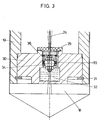
- An insert 30 is inserted into the lower end of the sleeve 19 (see FIG. 3) and held in place by a snap ring 31.
- the part 30 has a cavity 32 in which a spherical bearing 33 is arranged, with the spherical part 34 of which the plunger 24 is screwed.
- the cavity 32 is filled with a viscous liquid and covered by an elastic plate 35, for example made of rubber or plastic. This viscous liquid results in damping and also lubrication of the spherical bearing 33, 34.
- the pivot center of the plunger 24 given by the bearing 33, 34 is designated by 36. In the illustrated position of the crushing cone 1, this pivot center 36 coincides approximately with the pendulum center 15 of the crushing cone 1.
- the pivot center 36 of the plunger anchor does not match the pendulum center 15 of the crushing cone 1 in all positions. However, this is offset by the fact that the plunger 24 consists of a flexible rod or is arranged on a flexible rod.
- the housing 17 is formed in two parts for the purpose of assembly.
- An insert ring 37 holds the bearing 7 in place.
- the attachment point 22 for the tubular part 23 of the displacement sensor 21 is located on a bracket 38 rigidly connected to the housing 17.
Landscapes
- Engineering & Computer Science (AREA)
- Mechanical Engineering (AREA)
- Food Science & Technology (AREA)
- Crushing And Grinding (AREA)
Applications Claiming Priority (2)
| Application Number | Priority Date | Filing Date | Title |
|---|---|---|---|
| AT0141184A AT379761B (de) | 1984-04-27 | 1984-04-27 | Kegelbrecher |
| AT1411/84 | 1984-04-27 |
Publications (2)
| Publication Number | Publication Date |
|---|---|
| EP0159975A2 true EP0159975A2 (fr) | 1985-10-30 |
| EP0159975A3 EP0159975A3 (fr) | 1987-02-25 |
Family
ID=3513312
Family Applications (1)
| Application Number | Title | Priority Date | Filing Date |
|---|---|---|---|
| EP85890083A Withdrawn EP0159975A3 (fr) | 1984-04-27 | 1985-03-28 | Broyeur à cône |
Country Status (3)
| Country | Link |
|---|---|
| US (1) | US4664318A (fr) |
| EP (1) | EP0159975A3 (fr) |
| AT (1) | AT379761B (fr) |
Cited By (1)
| Publication number | Priority date | Publication date | Assignee | Title |
|---|---|---|---|---|
| US4856716A (en) * | 1987-09-10 | 1989-08-15 | Boliden Aktiebolag | Gyratory crusher control |
Families Citing this family (3)
| Publication number | Priority date | Publication date | Assignee | Title |
|---|---|---|---|---|
| DE19754320C1 (de) * | 1997-12-08 | 1999-08-05 | Reinhard Wild | Vorrichtung zur Messung der Spaltweite bei einem Kegelbrecher |
| CN114370839B (zh) * | 2022-03-22 | 2022-06-17 | 潍坊埃锐制动系统有限公司 | 一种用于制动鼓总成的锥形轴承游隙的检测工装 |
| CN115492930A (zh) * | 2022-10-07 | 2022-12-20 | 山东博研粉体技术装备有限公司 | 用于液压破碎机的活塞以及包含该活塞的液压破碎机 |
Citations (1)
| Publication number | Priority date | Publication date | Assignee | Title |
|---|---|---|---|---|
| DE2051398A1 (de) * | 1970-08-05 | 1972-04-20 | Saito, Hisatuna, Tokio | Vorrichtung zum Regeln des Spaltes einer Kegelmühle |
-
1984
- 1984-04-27 AT AT0141184A patent/AT379761B/de not_active IP Right Cessation
-
1985
- 1985-03-28 EP EP85890083A patent/EP0159975A3/fr not_active Withdrawn
- 1985-04-16 US US06/723,898 patent/US4664318A/en not_active Expired - Fee Related
Patent Citations (1)
| Publication number | Priority date | Publication date | Assignee | Title |
|---|---|---|---|---|
| DE2051398A1 (de) * | 1970-08-05 | 1972-04-20 | Saito, Hisatuna, Tokio | Vorrichtung zum Regeln des Spaltes einer Kegelmühle |
Cited By (1)
| Publication number | Priority date | Publication date | Assignee | Title |
|---|---|---|---|---|
| US4856716A (en) * | 1987-09-10 | 1989-08-15 | Boliden Aktiebolag | Gyratory crusher control |
Also Published As
| Publication number | Publication date |
|---|---|
| AT379761B (de) | 1986-02-25 |
| ATA141184A (de) | 1985-07-15 |
| EP0159975A3 (fr) | 1987-02-25 |
| US4664318A (en) | 1987-05-12 |
Similar Documents
| Publication | Publication Date | Title |
|---|---|---|
| DE102012206755B4 (de) | Steuerstangenanordnung | |
| DE60005340T2 (de) | Kolloidmühle | |
| DE2233324B2 (de) | Vorrichtung zur Bohrlochmessung während der Bohrung | |
| EP0159975A2 (fr) | Broyeur à cône | |
| DE1939956A1 (de) | Umlaufender Schraemer fuer eine bergmaennische Hereingewinnungsmaschine | |
| EP1901040A2 (fr) | Capteur d'angle de rotation sans contact | |
| DE3525766A1 (de) | Unwuchtkegelbrecher | |
| DE2349287C3 (de) | FormschlieBeinheit für Kunststoff Spritzgießmaschinen | |
| DE3521460A1 (de) | Unwuchtkegelbrecher | |
| DE2511083A1 (de) | Elektrisch angetriebener hammer mit beidseits im gehaeuse gelagerter kurbelwelle | |
| DE2243312A1 (de) | Kreiselbrecher | |
| DE19634047C2 (de) | Druckmittelbetätigter Kreismesserhalter | |
| DE3011242A1 (de) | Kreiselbrecher | |
| DE1175057B (de) | Elektromotorisch angetriebenes Druckfluessigkeitsverstellgeraet | |
| EP0411729B1 (fr) | Installation de coulée continue avec un équipement d'oscillation des lingotières | |
| DE2435733A1 (de) | Haengezentrifuge fuer intermittierenden betrieb | |
| DE10248772B4 (de) | Antriebseinheit | |
| DE19522853C2 (de) | Anordnung für den Antrieb des Schaufelrads eines Schaufelradgeräts | |
| EP0541046A1 (fr) | Pompe à hélice avec réglage des pales | |
| DE764254C (fr) | ||
| DE102005012523A1 (de) | Vorrichtung zur Bestimmung und/oder Überwachung des Füllstands eines Füllguts | |
| DE1048982B (de) | Drehzahlabhaengiger elektrischer Schalter | |
| DE1952047A1 (de) | Unwuchtwelle fuer Vibrationswalzen | |
| DE940743C (de) | Schmiervorrichtung fuer Lager mit schwingender, senkrechter Welle, insbesondere des inneren Exzenterlagers bei Kreiselbrechern | |
| DE2307022A1 (de) | Exzentrisch regelbare halterung auf waelzlagern |
Legal Events
| Date | Code | Title | Description |
|---|---|---|---|
| PUAI | Public reference made under article 153(3) epc to a published international application that has entered the european phase |
Free format text: ORIGINAL CODE: 0009012 |
|
| AK | Designated contracting states |
Designated state(s): BE CH DE FR GB IT LI LU NL SE |
|
| PUAL | Search report despatched |
Free format text: ORIGINAL CODE: 0009013 |
|
| AK | Designated contracting states |
Kind code of ref document: A3 Designated state(s): BE CH DE FR GB IT LI LU NL SE |
|
| 17P | Request for examination filed |
Effective date: 19870522 |
|
| 17Q | First examination report despatched |
Effective date: 19880725 |
|
| STAA | Information on the status of an ep patent application or granted ep patent |
Free format text: STATUS: THE APPLICATION IS DEEMED TO BE WITHDRAWN |
|
| 18D | Application deemed to be withdrawn |
Effective date: 19881204 |
|
| RIN1 | Information on inventor provided before grant (corrected) |
Inventor name: ZINK, FRANZ |