EP0159543B1 - Arbeitsplattformbefestigung für hydraulischen Kran - Google Patents
Arbeitsplattformbefestigung für hydraulischen Kran Download PDFInfo
- Publication number
- EP0159543B1 EP0159543B1 EP19850103291 EP85103291A EP0159543B1 EP 0159543 B1 EP0159543 B1 EP 0159543B1 EP 19850103291 EP19850103291 EP 19850103291 EP 85103291 A EP85103291 A EP 85103291A EP 0159543 B1 EP0159543 B1 EP 0159543B1
- Authority
- EP
- European Patent Office
- Prior art keywords
- platform
- boom
- latchable
- bracket
- aerial platform
- Prior art date
- Legal status (The legal status is an assumption and is not a legal conclusion. Google has not performed a legal analysis and makes no representation as to the accuracy of the status listed.)
- Expired
Links
- 239000006096 absorbing agent Substances 0.000 claims description 5
- 230000035939 shock Effects 0.000 claims description 5
- 239000000463 material Substances 0.000 description 2
- 239000000725 suspension Substances 0.000 description 2
- 238000013459 approach Methods 0.000 description 1
- 230000000712 assembly Effects 0.000 description 1
- 238000000429 assembly Methods 0.000 description 1
- 239000004020 conductor Substances 0.000 description 1
- 239000011152 fibreglass Substances 0.000 description 1
- 230000005484 gravity Effects 0.000 description 1
- 238000012986 modification Methods 0.000 description 1
- 230000004048 modification Effects 0.000 description 1
- 230000000717 retained effect Effects 0.000 description 1
Images

Classifications
-
- B—PERFORMING OPERATIONS; TRANSPORTING
- B66—HOISTING; LIFTING; HAULING
- B66F—HOISTING, LIFTING, HAULING OR PUSHING, NOT OTHERWISE PROVIDED FOR, e.g. DEVICES WHICH APPLY A LIFTING OR PUSHING FORCE DIRECTLY TO THE SURFACE OF A LOAD
- B66F11/00—Lifting devices specially adapted for particular uses not otherwise provided for
- B66F11/04—Lifting devices specially adapted for particular uses not otherwise provided for for movable platforms or cabins, e.g. on vehicles, permitting workmen to place themselves in any desired position for carrying out required operations
- B66F11/044—Working platforms suspended from booms
- B66F11/046—Working platforms suspended from booms of the telescoping type
Definitions
- This invention relates generally to aerial platform attachments and, more particularly, to such platform attachments which may be attached to and used with hydraulic cranes.
- the aerial attachment of the present invention is for use with cranes having a boom comprising relatively extendible and retractable boom sections; the aerial platform being pivotally mountable on the uppermost boom section, as considered with the boom extended upwardly, so as to be capable of being movable to an inactive storage position adjacent said boom.
- First storage means carried by the aerial platform is engageable with second storage retaining means carried by the lowermost section of the boom.
- the aerial platform attachment includes means for swinging said platform against the boom while the boom sections are not wholly retracted; the aforesaid first and second storage retaining means being such that a final retracting telescoping movement of said boom sections causes said storage retaining means to engage each other to secure said platform in its inactive position; and an extending action of said boom sections whilst said platform is in said inactive position causes said storage means to release their engagement with each other to permit the platform to swing to its suspended operating position.
- the present invention also provides an aerial platform attachment that includes a side plate for securement to a boom tip, said side plate having a pair of cross shafts extending therefrom; a bracket removably attached to said cross shafts; the aerial platform being pivotally attached to said bracket; and a hand-operated brake arranged to prevent relative movement between said bracket and said platform.
- the pivotal suspension permits the platform to remain level as the crane boom is elevated, while the pinned connection to the cross-shafts allow the attachment to be readily removed and reinstalled.
- the platform includes a basket and is positioned adjacent to the boom tip so that tools or other light materials may be exchanged between the ground and the basket by means of the whip line on the crane.
- a dash pot preferably in the form of an automotive shock absorber, attached between the bracket and the platform controls the rate of movement and hence prevents any sudden rotational movement of the platform relative to the boom tip as the boom is elevated into a desired working position.
- the hand operated brake is provided to prevent rotation of the platform relative to the boom tip while the platform is occupied and in a working position.
- an aerial platform attachment for a crane having relatively extendible and retractable boom sections is already known from GB-A-1 572 440, said attachment comprising a side plate for securement to a boom tip, said side plate having a pair of cross shafts extending therefrom; and a bracket removably attached to said cross shafts, the aerial platform being pivotally attached to said bracket.
- US-A-3 710 893 discloses a power extendible crane boom having a work basket pivoted between yoke arms mounted on the end of the boom and provided with means for swinging said basket against the boom. Integral with each yoke arm is a plate having an arcuate slot, the centre of radius of which coincides with the pivot pins about which the basket swings. Wing nut-bolt-washer assemblies carried by the basket and extending through said arcuate slots enable the basket to be locked against swinging movement in any selected position.
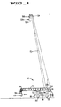
- a hydraulic crane indicated generally at 10, having a multi- section, extendable boom 12 pivotally mounted on the crane's upper 14.
- the upper is rotatable about a vertical axis on the lower 16.
- the entire crane 10 is supported for stability on outrigger jacks 18, which may be retracted to permit the wheels 20 on the lower 16 to engage the ground for transport in a conventional manner.
- Hydraulic cylinder means 22 is connected between the boom 12 and the upper 14. With both the boom and the cylinder means 22 fully retracted, the boom 12 is oriented as indicated by solid lines and when both the boom and the cylinder means are fully extended, the boom 12 is configured as indicated by dotted lines in Figure 1.
- An aerial platform 23 is pivotally suspended from a boom tip 24 secured on the free end of the outer section of the boom 12.
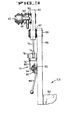
- An auxiliary hoist 26 mounted on the upper 14 has a wire rope 28, commonly referred to as a whipline, wound thereon and trained over a sheave 30, as shown in Figure 2, rotatably carried on a cross-shaft between the side plates, one of which is shown at 32, of the boom tip 24 and an auxiliary sheave 34 on a shaft cantilevered from the tip 24 by means of arm 36.
- a hook 38 is attached to the free end of the wire rope 28.
- the hook 38 will, as it approaches the boom tip as a result of the auxiliary hoist reeling in the wire rope 28, be in close proximity to the platform 23 to enable a worker on the platform to remove or attach material from or to the hook.
- a bracket 44 has a pair of tubes 46 and 48 secured thereon, which tubes engage the ends of the cross-shafts 40 and 42 respectively.
- the tubes are cross-bored in alignment with bores provided in end fittings on the cross-shafts, one of which is shown at 50.
- a pair of pins, one of which is shown at 52 inserted through the tube 48 and the fitting 50, releasably secure the bracket 44 to the boom tip 24.
- the aerial platform 23 includes a basket 54, preferably constructed of an electrically non-conducting material, such as fiberglass, secured to a suspension link 56.
- the link 56 is pivotally connected to the bracket 44 by means of a pivot pin 58 attached to the link 56 and rotatably retained within a bushing 60 provided in the bracket 44.
- a dash pot which may be an automotive shock absorber 62, is pivotally attached at 64 to the bracket 44 and at 66 to an arm 68 secured to the link 56. Rotatation of the link 56 clockwise, is viewed in Figure 2, will cause extension of the shock absorber 62, and rotation in the opposite direction will cause retraction.
- the shock absorber 62 will control the rate of such rotation, and hence will preclude any sudden rotational movement to the basket 54 while the boom is being elevated or lowered.
- the basket 54 will remain virtually vertical when moved to and from a working position. Movement of the occupant and the shifting of his or her center of gravity resulting therefrom will not cause an unsettling and unexpected sudden rotation of the basket.
- a brake, indicated generally at 70, is provided to lock the link 56 relative to the bracket 44.
- the brake 70 includes a rotor sector 72 secured to the bracket 44.
- Calipers 74 carried by an actuating member 76 secured to the link 56 are capable of engaging the rotor sector 72 to lock the link 56 to the bracket 44.
- An actuating lever 78 rotatably mounted on the member 76 has a central position, wherein the caliper 74 are out of engagement with sector 72 permitting pivoting of the link 56 relative to the bracket 44, and movement in either direction from its central position causes the caliper 74 to engage to sector 72 thereby locking the link 56 to the bracket 44.
- Movement of the actuating levers 78 is controlled by a one way control device 80, such as that made by Quadrastat Controls Corp.
- the control 80 has an input means 82 and output means 84.
- a hand lever 86 is affixed to the input means 82 and the link 88 is pivotally connected between the output means 84 and the actuating lever 78.
- the control permits rotation of the output means 84 when a force is applied to the lever 86, but precludes such movement when forces are applied to the output means 84. Consequently, the brake 70 can be released or engaged only through manipulation of the lever 86, and unintentional release or engagement as a result of vibration or other forces applied to the output means 84 will be precluded.
- the position of the hand lever 86 when the brake 70 is released is shown by solid lines in Figure 2 and movement of this lever to either of the dotted line positions will cause the break to engage. Thus, should an occupant need to quickly apply the brake 70 he or she would not have to consider which direction to rotate the hand lever; the brake 70 will be engaged with movement in either direction.
- a loop 90 is attached to the side of the basket 54 adjacent to the boom and along the basket's bottom edge.
- a stabber member 92 is formed on a bracket 94 attached to the boom 12. The stabber member 92 engages the loop 90 when the basket is held parallel to the bottom of the boom and the boom is then fully retracted.
- An inclined surface 96 on the stabber member 92 cams the basket 54 upward to facilitate full engagement of the loop 90 by the stabber member 92 should the basket 54 not be perfectly parallel to the bottom of the boom 12.
- a rope 95 may be attached to a second loop 98 secured to the basket 54 and passed through a third loop 100 attached to bracket 94. Tension force applied to the rope 95 permits rotation of the basket 54 to its proper position for engagement of the stabber 92 with the_ loop 90 from a remote position. When the boom is then fully retracted, the stabber 92 will engage the loop 90.
Landscapes
- Engineering & Computer Science (AREA)
- Structural Engineering (AREA)
- Life Sciences & Earth Sciences (AREA)
- Geology (AREA)
- Mechanical Engineering (AREA)
- Forklifts And Lifting Vehicles (AREA)
- Jib Cranes (AREA)
Claims (10)
Applications Claiming Priority (2)
| Application Number | Priority Date | Filing Date | Title |
|---|---|---|---|
| US59701084A | 1984-04-05 | 1984-04-05 | |
| US597010 | 1984-04-05 |
Publications (3)
| Publication Number | Publication Date |
|---|---|
| EP0159543A2 EP0159543A2 (de) | 1985-10-30 |
| EP0159543A3 EP0159543A3 (en) | 1986-06-25 |
| EP0159543B1 true EP0159543B1 (de) | 1989-07-12 |
Family
ID=24389680
Family Applications (1)
| Application Number | Title | Priority Date | Filing Date |
|---|---|---|---|
| EP19850103291 Expired EP0159543B1 (de) | 1984-04-05 | 1985-03-21 | Arbeitsplattformbefestigung für hydraulischen Kran |
Country Status (5)
| Country | Link |
|---|---|
| EP (1) | EP0159543B1 (de) |
| JP (1) | JPS60223788A (de) |
| AU (1) | AU571663B2 (de) |
| CA (1) | CA1235075A (de) |
| DE (1) | DE3571425D1 (de) |
Families Citing this family (2)
| Publication number | Priority date | Publication date | Assignee | Title |
|---|---|---|---|---|
| FR2644204A1 (fr) * | 1989-03-09 | 1990-09-14 | Camiva | Echelle telescopique avec basculement automatique de son panier de travail dans les positions de transport et de travail |
| WO2014194287A2 (en) | 2013-05-30 | 2014-12-04 | Cnh Industrial America Llc | Bale eject linkage and methods of use |
Family Cites Families (12)
| Publication number | Priority date | Publication date | Assignee | Title |
|---|---|---|---|---|
| US3605941A (en) * | 1969-01-09 | 1971-09-20 | Gen Cable Corp | Aerial lift with rotatable and enclosable basket |
| DE2106429A1 (de) * | 1971-02-11 | 1972-08-17 | Carl Metz Gmbh, 7500 Karlsruhe | Vorrichtung zur Führung und/oder Festlegung eines pendelnd aufgehängten Arbeits- und/oder Rettungskorbes |
| DE2107821A1 (de) * | 1971-02-18 | 1972-08-31 | Carl Metz Gmbh, 7500 Karlsruhe | Vorrichtung zur Führung und/oder Festlegung eines pendelnd aufgehängten Arbeits- und/oder Rettungskorbes |
| DE2129856A1 (de) * | 1971-06-16 | 1973-01-04 | Metz Gmbh Carl | Aushaengbarer arbeits- und/oder rettungskorb |
| US3710893A (en) * | 1971-06-21 | 1973-01-16 | Bliss & Laughlin Ind | Portable extendible crane with work basket |
| BE792745A (fr) * | 1971-12-15 | 1973-03-30 | Freen Ltd | Ecran pour projection par transparence |
| JPS5834883B2 (ja) * | 1973-08-22 | 1983-07-29 | 三菱電線工業株式会社 | チヨウコウアツケ−ブルノ セイゾウホウホウ |
| JPS5420801U (de) * | 1977-07-07 | 1979-02-09 | ||
| JPS5427761U (de) * | 1977-07-26 | 1979-02-23 | ||
| GB1572440A (en) * | 1978-04-06 | 1980-07-30 | Hongisto Oy | Working platform for cranes |
| US4334594A (en) * | 1978-12-13 | 1982-06-15 | Mccabe Powers Body Company | Aerial device |
| US4427121A (en) * | 1982-05-03 | 1984-01-24 | Clements Shannon K | Hydraulic valve control for aerial book devices |
-
1985
- 1985-03-13 AU AU39809/85A patent/AU571663B2/en not_active Ceased
- 1985-03-19 CA CA000476925A patent/CA1235075A/en not_active Expired
- 1985-03-21 DE DE8585103291T patent/DE3571425D1/de not_active Expired
- 1985-03-21 EP EP19850103291 patent/EP0159543B1/de not_active Expired
- 1985-04-02 JP JP6861585A patent/JPS60223788A/ja active Pending
Also Published As
| Publication number | Publication date |
|---|---|
| EP0159543A2 (de) | 1985-10-30 |
| CA1235075A (en) | 1988-04-12 |
| DE3571425D1 (en) | 1989-08-17 |
| AU571663B2 (en) | 1988-04-21 |
| JPS60223788A (ja) | 1985-11-08 |
| AU3980985A (en) | 1985-10-10 |
| EP0159543A3 (en) | 1986-06-25 |
Similar Documents
| Publication | Publication Date | Title |
|---|---|---|
| US5586667A (en) | Mobile crane with main and auxiliary counterweight assemblies | |
| US3076560A (en) | Retractible mast and boom stop | |
| EP0254510A1 (de) | Auslegerverlängerung für einen Hauptausleger | |
| US3278045A (en) | Counterweight support mechanism | |
| US4318488A (en) | Method of extending a jib of a telescopic crane | |
| JP2883860B2 (ja) | クレーンのジブ張出、格納装置及びその張出、格納方法 | |
| US4310098A (en) | Portable boom structure | |
| US4653654A (en) | Hydraulic crane aerial platform attachment | |
| US6065620A (en) | Movable sheave assembly for a crane | |
| CA1231066A (en) | Two person aerial platform | |
| EP0159543B1 (de) | Arbeitsplattformbefestigung für hydraulischen Kran | |
| JPH06219688A (ja) | ラフィングジブのバックストップ組立体 | |
| US3134488A (en) | Crane | |
| JP4241965B2 (ja) | 可搬式クレーン | |
| US3252585A (en) | Rigging for mobile tower crane having a topping jib-boom | |
| JPH0688757B2 (ja) | 車両形クレーンのジブ格納装置 | |
| US4606694A (en) | Load skidding vehicle | |
| JP3229743B2 (ja) | ジブ先端構造 | |
| US3092260A (en) | Back-hitch gaintry | |
| CN116161561B (zh) | 一种小型吊装搬运设备 | |
| JP7111130B2 (ja) | ジブ係留装置およびジブ係留方法 | |
| JP3537233B2 (ja) | ジブ張出、格納時のワイヤロープ掛換え装置及び方法 | |
| CN115043335A (zh) | 起重机中张设吊装载荷用缆索时所使用的缆索连结支撑件 | |
| JPS6323431Y2 (de) | ||
| JPH09194190A (ja) | ジブ起伏装置 |
Legal Events
| Date | Code | Title | Description |
|---|---|---|---|
| PUAI | Public reference made under article 153(3) epc to a published international application that has entered the european phase |
Free format text: ORIGINAL CODE: 0009012 |
|
| AK | Designated contracting states |
Designated state(s): DE FR GB IT |
|
| PUAL | Search report despatched |
Free format text: ORIGINAL CODE: 0009013 |
|
| AK | Designated contracting states |
Kind code of ref document: A3 Designated state(s): DE FR GB IT |
|
| 17P | Request for examination filed |
Effective date: 19860721 |
|
| 17Q | First examination report despatched |
Effective date: 19870626 |
|
| GRAA | (expected) grant |
Free format text: ORIGINAL CODE: 0009210 |
|
| AK | Designated contracting states |
Kind code of ref document: B1 Designated state(s): DE FR GB IT |
|
| REF | Corresponds to: |
Ref document number: 3571425 Country of ref document: DE Date of ref document: 19890817 |
|
| ITF | It: translation for a ep patent filed | ||
| ET | Fr: translation filed | ||
| PLBE | No opposition filed within time limit |
Free format text: ORIGINAL CODE: 0009261 |
|
| STAA | Information on the status of an ep patent application or granted ep patent |
Free format text: STATUS: NO OPPOSITION FILED WITHIN TIME LIMIT |
|
| 26N | No opposition filed | ||
| REG | Reference to a national code |
Ref country code: GB Ref legal event code: 732 |
|
| PGFP | Annual fee paid to national office [announced via postgrant information from national office to epo] |
Ref country code: FR Payment date: 19930215 Year of fee payment: 9 |
|
| PGFP | Annual fee paid to national office [announced via postgrant information from national office to epo] |
Ref country code: DE Payment date: 19930225 Year of fee payment: 9 |
|
| PGFP | Annual fee paid to national office [announced via postgrant information from national office to epo] |
Ref country code: GB Payment date: 19930226 Year of fee payment: 9 |
|
| ITTA | It: last paid annual fee | ||
| PG25 | Lapsed in a contracting state [announced via postgrant information from national office to epo] |
Ref country code: GB Effective date: 19940321 |
|
| GBPC | Gb: european patent ceased through non-payment of renewal fee |
Effective date: 19940321 |
|
| PG25 | Lapsed in a contracting state [announced via postgrant information from national office to epo] |
Ref country code: FR Effective date: 19941130 |
|
| PG25 | Lapsed in a contracting state [announced via postgrant information from national office to epo] |
Ref country code: DE Effective date: 19941201 |
|
| REG | Reference to a national code |
Ref country code: FR Ref legal event code: ST |