EP0157592A2 - Spritzgestänge - Google Patents
Spritzgestänge Download PDFInfo
- Publication number
- EP0157592A2 EP0157592A2 EP85302142A EP85302142A EP0157592A2 EP 0157592 A2 EP0157592 A2 EP 0157592A2 EP 85302142 A EP85302142 A EP 85302142A EP 85302142 A EP85302142 A EP 85302142A EP 0157592 A2 EP0157592 A2 EP 0157592A2
- Authority
- EP
- European Patent Office
- Prior art keywords
- boom
- suspension
- ground
- dimension
- vehicle
- Prior art date
- Legal status (The legal status is an assumption and is not a legal conclusion. Google has not performed a legal analysis and makes no representation as to the accuracy of the status listed.)
- Granted
Links
- 0 CCCCC[C@]1*CCCC1 Chemical compound CCCCC[C@]1*CCCC1 0.000 description 4
Images
Classifications
-
- A—HUMAN NECESSITIES
- A01—AGRICULTURE; FORESTRY; ANIMAL HUSBANDRY; HUNTING; TRAPPING; FISHING
- A01M—CATCHING, TRAPPING OR SCARING OF ANIMALS; APPARATUS FOR THE DESTRUCTION OF NOXIOUS ANIMALS OR NOXIOUS PLANTS
- A01M7/00—Special adaptations or arrangements of liquid-spraying apparatus for purposes covered by this subclass
- A01M7/005—Special arrangements or adaptations of the spraying or distributing parts, e.g. adaptations or mounting of the spray booms, mounting of the nozzles, protection shields
- A01M7/0053—Mounting of the spraybooms
- A01M7/0057—Mounting of the spraybooms with active regulation of the boom position
-
- B—PERFORMING OPERATIONS; TRANSPORTING
- B60—VEHICLES IN GENERAL
- B60G—VEHICLE SUSPENSION ARRANGEMENTS
- B60G2300/00—Indexing codes relating to the type of vehicle
- B60G2300/08—Agricultural vehicles
- B60G2300/083—Boom carrying vehicles, e.g. for crop spraying
Definitions
- This invention relates to boom assemblies and in particular to boom assemblies for agricultural use.
- UK Patent 2028078 describes a boom assembly suspended by a plurality of links having inclined lines of action to provide stabilising or restoring forces on the boom against forces displacing the boom from a desired position.
- This arrangement is very effective in stabilising the position of a boom when a vehicle on which the boom is used, e.g. for spraying argicultural treatment liquids, is travelling over bumpy ground.
- the boom has to be stabilised to ensure uniformity of spray deposit in terms of area of ground covered from each sprayhead.
- certain ground conditions can cause the boom to adopt positions in which the spray deposit is not uniform. These ground conditions include undulations of relatively long wavelength and ground of varying softness.
- the latter in particular can cause the vehicle carrying the boom to adopt a tilted attitude with respect to the ground surface for some distance, which attitude is followed by the boom, because of the differential deflection of the vehicle tyres, and suspension if provided, with the tilted altitude of the vehicle.
- a boom suspension including a passive suspension arrangement to suspend a boom frame support to stabilise the position with respect to the support of a boom suspended thereby and means to force an alteration in at least one set dimension of the passive arrangement to produce a boom position altered from said stabilised suspended position and means to control the means to force said alteration in a said dimension to provide a continuous correction of a displacement more slowly than the stabilisation action of the passive suspension of the whole boom and suspension.
- the suspension is fitted on a vehicle and the passive suspension stabilises the boom against displacement from a desired position when the vehicle moves over uneven ground while the action of the forcible alteration of a dimension corrects for displacement of the whole boom and suspension by movement of the vehicle itself from its normal attitude with respect to the ground surface when, for example, it tilts on its own suspension or tyres on a slope or lurches into a hollow in the ground.
- control means includes a distance sensor to measure the distance of the boom from the ground and means responsive to said measurement to determine the alteration in said dimension to correct the distance of the boom from the ground and means responsive to said determination to alter said dimension to continuously correct the distance of the boom from the ground.
- the distance sensor may be a plurality of ultrasonic ranging devices along the boom and the control means may be effective to maintain a substantially equal distance at each device by said alteration of said dimension.
- the dimension may be the set length of a link in the passive suspension.
- the dimension may be the set distance between pivots of the passive suspension.
- the control means is preferably arranged to force length alterations more slowly than the response rate of the links of set length so that the performance of the links is not adversely affected.
- the forced rate of change of length of a link is made proportional to the measured difference between the angle of inclination of the boom and that of the ground.
- the response of the control means is generally restricted to below 10 rad/s and in one tractor borne arrangement where the links of set length are effective for frequencies above about 0.7 rad/s is restricted to below 0.6 rad/s.
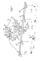
- FIG 1 shows, in schematic form, a boom suspension according to the invention. This is conveniently arranged on a boom as described in UK Patent Specification 2028078B.
- Two links, 16 and 18, the set length of which can be forcibly altered, are provided in the suspension of boom 10. Two links of alterable length are shown but in many cases one only is sufficient and this case is included in references to two links.
- Boom 10 carries a number, in this case four, sensors 51, 52, 53, 54, which can measure the distance between the boom and the ground. This action is represented by the beam of radiation 55 but any suitable sensor technique, such as ultrasonic, capacitive, electromagnetic, can be used.
- a control unit, 40 is conveniently mounted on the support 12 and receives signals at connections 41, 42, 43, 44 from the sensors 51 to 54. The control unit receives a suitable electrial supply 47 from the vehicles using the boom.
- the control unit also provides, in dependence on the signals from the sensors and any control parameters built into it, fluid pressure to operate links 16 and 18.
- the control unit may include a microprocessor to achieve the control function.
- Connections 45 and 46 are extended, flexibly if necessary, to the links 16 and 18.
- Conveniently links 16 and 18 include pneumatic or hydraulic actuators of the piston and cylinder type which can be altered in length by supply or release of fluid pressure.
- unit 40 can include a pump or compressor. Hydraulic or pneumatic power may be available from the vehicle and only need to be controlled by unit 40.
- control unit The action of the control unit is to respond to signals from sensors 51 to 54 to forcibly alter the lengths of links 16 and 18 to maintain a substantially uniform distance between the boom and the ground surface represented at 1. Clearly with a long boom and uneven ground the same distance can not be maintained at all points along the boom but a suitable compromise, as described below, is aimed at.
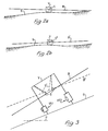
- Figure 2 shows how, with certain ground conditions, the technique of keeping the boom level across the vehicle is disadvantageous.
- the suspension with fixed length links is indicated at S.
- Figure 2a As the vehicle tilts ( Figure 2a) on a particular area of the undulating ground G the suspension S keeps the boom "square" across the vehicle by filtering out the fairly rapid vehicle roll frequencies.
- the extremities of the boom B may now be in adverse positions or even, on a long boom, be in contact with the ground.
- a further problem is that the vehicle itself can tilt, on its tyres and suspension, to an angle greater than the actual slope of the ground it is traversing.
- Figure 2b shows that the effect of the suspension according to the invention, S', is to modify the action of suspension S so that the boom B' is not necessarily "square" across the vehicle but is more equally distanced from the ground G.
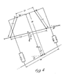
- FIG 3 shows the vehicle and its own tyres and suspension in more detail to illustrate the effect of the boom suspension.
- the suspension and tyres are represented by the damped fluid pressure units VS1, VS2, the other references are as in Figures 2a and 2b.
- the vehicle V tilts more than the slope of ground G to the horizontal, H, because of the deflection of suspension and tyres.
- With a boom suspension of fixed length links S the boom B tilts with respect to the ground G by the extra tilt of the vehicle.
- links S' of forcibly adjustable length the boom can be brought to a position in which it is substantially parallel to the ground surface G.
- the speed and frequency response of the control system is thus very important. It is also important to be able to retain the action of the set length links where appropriate.
- the rolling motion of a vehicle on undulating ground can be broadly separated into a high frequency component and a low frequency component.
- the high frequency component is attenuated by the fixed length link arrangement but the low frequency component is used by this invention to adjust the boom by the forcible adjustment of link length.
- the exact values defined as high and low frequency will of course vary with ground shape and vehicle speed but can be adequately classified for practical cases.
- the sensors of boom distance from the gound can be arranged to respond to the upper surface of a growing crop rather than the ground, but this does not alter the following discussion.
- the response function should have the value to ensure that the boom follows the vehicle motion by the action of the fixed length linkage and this value should reduce to zero at a higher roll frequency to isolate the boom from shorter-term displacements of the vehicle.
- the boom suspension should similarly have a resonant frequency which is low but above the field condition frequency. In one case the resonant frequency was about three times the field condition frequency, providing the required attentuation of the higher frequencies.
- the damping of the boom suspension using fixed length links is arranged to be only large enough to permit the field condition frequency to be followed as well as possible. Excessive damping adversely effects performances at this frequency and allows higher frequencies, especially those above the resonant frequency, to excite the suspension.
- This behaviour includes the ability of any electro-fluid- pressure device used to follow the signals from the distance sensors.
- this device could include the sensor, an electrically operated fluid pressure valve and the piston-and- cylinder actuator in the forcibly adjustable link.
- Such a practical device was found capable of linear operation at angular velocities of up to about 1 rad/s. Also an upper limit for the motion frequency to which the forcibly adjustable link should respond was identified at 10 rad/s.
- the gain of the electro- fluid-pressure device is also significant. Too high a gain can make the system unstable. The gain is conveniently expressed as the rate of change of the length of the link per radian of net inclination of the boom to the ground. If the gain is too small the system does not respond enough to maintain the required relationship to the ground.
- a control valve in control unit 40 responds to signals from the sensors and supplies fluid pressure to an actuator of a forcibly adjustable link.
- the overall response of the sensors, the valve and the actuator is represented by a relation between the gain, G, of the control means in terms of the forcible alteration of link length for change in inclination of the boom to the ground and a time constant T of the control valve and the sensor.
- L2 When one forcibly adjustable link, L2, is used the change in L2, L2, is expressed as follows:- where s is the Laplace operator.
- Such an amplitude ratio (1.2) represents for a 10 m boom on a vehicle at rest tilted on its suspension across a slope of 10° a difference of 350 mm between the ground clearances at the ends of the boom. Dynamically a ratio above 1.0 exaggerates the tilting of the vehicle in its effect on the boom position in a similar manner.
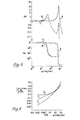
- FIG. 5 shows the variation of amplitude ratio AR and phase advance PA for a rigidly attached boom (curve A) a boom with set length link suspension (curve B) and with forcibly alterable length link suspension (curve C) for a range of frequencies produced by undulating ground including the lower (below some 0.6 rad/s) and higher frequencies.
- the peak at about 7 rad/s is the effect of vehicle suspension and the attenuation of the response is well-shown.
- the value of G is 0.3 ms -1 rad -1 and T is 0.5 s.
- Figure 6 shows the performance of the embodiment specifically described in terms of the angle between the boom and the ground (y - 8) and the slope of the ground (y) for the same values of T at G values of 0 (curve D) 0.1 (curve E) and 0.3 (curve F). Other values of T do not significantly alter this response. The values of w are below resonance of the boom and show the considerable control achieved.
- the power required to achieve such control is not great. A few tens of watts are sufficient and this power is readily available from a spray vehicle. The power requirements are so small that a wholly electrical control means can be used with an electrical actuator such as a screw-operated type. Clearly a fluid pressure actuation can be used if preferred.
- a total power for the control means and actuator of about 100 watts is considered adequate.
- control or the actuator should fail the suspension can revert to the set length link condition and perform as expected for this configuration.
- the suspension according to the invention provides a significant extension to the range of operation of the set length link suspension, coping with ground and vehicle induced displacements of the boom to produce a stable boom attitude down to very low disturbance frequencies such as 0.01 rad/s.
- the identification of the importance of the gain of the control means to the proper operation and the relative unimportance of the speed of response, as well as the quite small power required, permit an effective suspension to be provided for various sizes of boom and operating conditions.
- the invention has been specifically described with reference to the adjustment of the length of a link.
- other dimensions in the passive suspension can be adjusted together with or instead of the length of a link.
- the distance between pivots 20 and 26 and/or pivots 22 and 24 could be altered.
Landscapes
- Life Sciences & Earth Sciences (AREA)
- Engineering & Computer Science (AREA)
- Insects & Arthropods (AREA)
- Pest Control & Pesticides (AREA)
- Wood Science & Technology (AREA)
- Zoology (AREA)
- Environmental Sciences (AREA)
- Vehicle Body Suspensions (AREA)
- Catching Or Destruction (AREA)
Applications Claiming Priority (2)
| Application Number | Priority Date | Filing Date | Title |
|---|---|---|---|
| GB848407913A GB8407913D0 (en) | 1984-03-27 | 1984-03-27 | Boom assemblies |
| GB8407913 | 1984-03-27 |
Publications (3)
| Publication Number | Publication Date |
|---|---|
| EP0157592A2 true EP0157592A2 (de) | 1985-10-09 |
| EP0157592A3 EP0157592A3 (en) | 1987-10-21 |
| EP0157592B1 EP0157592B1 (de) | 1992-04-29 |
Family
ID=10558747
Family Applications (1)
| Application Number | Title | Priority Date | Filing Date |
|---|---|---|---|
| EP19850302142 Expired EP0157592B1 (de) | 1984-03-27 | 1985-03-27 | Spritzgestänge |
Country Status (6)
| Country | Link |
|---|---|
| EP (1) | EP0157592B1 (de) |
| AU (1) | AU589894B2 (de) |
| DE (1) | DE3585926D1 (de) |
| DK (1) | DK136285A (de) |
| GB (2) | GB8407913D0 (de) |
| NZ (1) | NZ211556A (de) |
Cited By (21)
| Publication number | Priority date | Publication date | Assignee | Title |
|---|---|---|---|---|
| FR2595060A1 (fr) * | 1986-03-03 | 1987-09-04 | Tecnoma | Dispositif de suspension pour rampes de pulverisation |
| FR2603453A1 (fr) * | 1986-09-10 | 1988-03-11 | Inst Pflanzenschutzforschung | Dispositif de regulation de la position, parallelement au sol, d'un bras articule sur des machines de traitement des vegetaux |
| EP0269829A1 (de) * | 1986-11-05 | 1988-06-08 | Amazonen-Werke H. Dreyer GmbH & Co. KG | Verteilmaschine, insbesondere Grossflächendüngerstreuer |
| WO1990001265A1 (de) * | 1988-08-11 | 1990-02-22 | Alois Assfalg | Vorrichtung zum behandeln von pflanzenkulturen, mit wenigstens einem unter abstand vom erdboden lotrecht über der pflanzenkultur bewegbar angeordneten einrichtungsträger |
| FR2669804A1 (fr) * | 1990-11-29 | 1992-06-05 | Agro Electronique France | Dispositif de rappel automatique en position de reference d'une rampe de distribution de produit liquide ou en poudre pour machine agricole du type pulverisateur ou distributeur d'engrais. |
| WO1992020214A1 (de) * | 1991-05-17 | 1992-11-26 | Dieter Trommer | Fahrbare beregnungsmaschine mit einem tragwerk |
| WO1993002552A1 (en) * | 1991-08-06 | 1993-02-18 | Benest Engineering Limited | Method and apparatus for crop spraying |
| FR2690811A1 (fr) * | 1991-06-21 | 1993-11-12 | Matrot Louis | Suspension perfectionnée de rampe de pulvérisateur. |
| EP0922385A1 (de) * | 1997-12-10 | 1999-06-16 | Amazonen-Werke H. Dreyer GmbH & Co. KG | Landwirtschaftliche Maschine zum Verteilen von Material, vorzugsweise Feldspritze |
| WO2001003503A1 (fr) | 1999-07-09 | 2001-01-18 | Michel Barrau | Dispositif de controle automatique de niveau d'inclinaison d'une rampe de pulverisation |
| EP1167095A1 (de) | 2000-06-26 | 2002-01-02 | K.U. Leuven Research & Development | Verfahren und Vorrichtung zur Steuerung und Stabilisierung einer Bewegung |
| EP1356729A1 (de) * | 2002-04-02 | 2003-10-29 | CLAAS Selbstfahrende Erntemaschinen GmbH | Messeinrichtung an einer landwirtschaftlichen Maschine |
| EP1444894A1 (de) * | 2003-02-10 | 2004-08-11 | Norac Systems International Inc. | System und Verfahren für die Rollregelung eines aufgehängten Gestänges |
| US6834223B2 (en) | 2003-02-10 | 2004-12-21 | Norac Systems International, Inc. | Roll control system and method for a suspended boom |
| EP2248690A3 (de) * | 2009-05-08 | 2012-05-02 | Herbert Dammann GmbH | Fahrgestell für Spezialfahzeuge |
| EP2591657A1 (de) * | 2011-11-08 | 2013-05-15 | HORSCH LEEB Application Systems GmbH | Fahrbare Vorrichtung zum Ausbringen von flüssigen und/oder festen Wirkstoffen und Verfahren zur Steuerung der Vorrichtung |
| EP2397027A3 (de) * | 2010-06-18 | 2013-10-23 | CLAAS Selbstfahrende Erntemaschinen GmbH | Landwirtschaftliche Erntemaschine |
| EP3064061A1 (de) | 2015-03-02 | 2016-09-07 | HORSCH LEEB Application Systems GmbH | Vorrichtung zum ausbringen von flüssigen und/oder festen wirkstoffen und verfahren zur steuerung einer solchen vorrichtung |
| DE202014011019U1 (de) | 2013-10-14 | 2017-05-16 | Horsch Leeb Application Systems Gmbh | Vorrichtung zum Ausbringen von flüssigen und/oder festen Wirkstoffen |
| EP3106030A4 (de) * | 2014-07-11 | 2017-12-13 | KYB Corporation | Vorrichtung zur vibrationskontrolle bei einem ausleger und auslegersprüher |
| US10244747B2 (en) | 2013-11-10 | 2019-04-02 | Horsch Leeb Application Systems Gmbh | Apparatus and method for discharging liquid and/or solid active substances |
Families Citing this family (2)
| Publication number | Priority date | Publication date | Assignee | Title |
|---|---|---|---|---|
| GB2184633A (en) * | 1985-12-19 | 1987-07-01 | Billericay Farm Services Ltd | Boom mounting arrangement |
| US5348226A (en) * | 1992-11-12 | 1994-09-20 | Rhs Fertilizing/Spraying Systems | Spray boom system with automatic boom end height control |
Citations (6)
| Publication number | Priority date | Publication date | Assignee | Title |
|---|---|---|---|---|
| FR1564543A (de) * | 1968-01-04 | 1969-04-25 | ||
| GB2014834A (en) * | 1978-02-13 | 1979-09-05 | Moteska Svenska Ab | Improvement in or relating to sprayers |
| GB2025665A (en) * | 1978-03-28 | 1980-01-23 | Allman & Co Ltd | Improvements in or relating to spraying equipment |
| GB2028078A (en) * | 1978-08-22 | 1980-03-05 | British Res Agricult Eng | Improvements in and relating to boom assemblies |
| EP0077270A2 (de) * | 1981-10-09 | 1983-04-20 | Centre National Du Machinisme Agricole, Du Genie Rural, Des Eaux Et Des Forets (Cemagref) | Verfahren zum Stabilisieren eines mit mindestens einem Freiheitsgrad beweglichen Elementes im Sinne einer gewünschten Bahn, sowie dessen Anwendung zum Stabilisieren eines Sprühbalkens |
| LU83957A1 (fr) * | 1983-08-11 | 1983-09-02 | Pierre Demaret | Perfectionnement aux dispositifs de montage de rampes destinees aux machines agricoles |
Family Cites Families (2)
| Publication number | Priority date | Publication date | Assignee | Title |
|---|---|---|---|---|
| AU7373681A (en) * | 1980-06-18 | 1982-01-07 | Tyler, L. | Positioning apparatus for boom structures |
| CA1172291A (en) * | 1981-10-07 | 1984-08-07 | R. Barry Rogers | Boom stabilizing system |
-
1984
- 1984-03-27 GB GB848407913A patent/GB8407913D0/en active Pending
-
1985
- 1985-03-25 NZ NZ21155685A patent/NZ211556A/en unknown
- 1985-03-26 AU AU40456/85A patent/AU589894B2/en not_active Ceased
- 1985-03-26 DK DK136285A patent/DK136285A/da not_active Application Discontinuation
- 1985-03-27 DE DE8585302142T patent/DE3585926D1/de not_active Expired - Lifetime
- 1985-03-27 EP EP19850302142 patent/EP0157592B1/de not_active Expired
- 1985-03-27 GB GB08508005A patent/GB2156193B/en not_active Expired
Patent Citations (6)
| Publication number | Priority date | Publication date | Assignee | Title |
|---|---|---|---|---|
| FR1564543A (de) * | 1968-01-04 | 1969-04-25 | ||
| GB2014834A (en) * | 1978-02-13 | 1979-09-05 | Moteska Svenska Ab | Improvement in or relating to sprayers |
| GB2025665A (en) * | 1978-03-28 | 1980-01-23 | Allman & Co Ltd | Improvements in or relating to spraying equipment |
| GB2028078A (en) * | 1978-08-22 | 1980-03-05 | British Res Agricult Eng | Improvements in and relating to boom assemblies |
| EP0077270A2 (de) * | 1981-10-09 | 1983-04-20 | Centre National Du Machinisme Agricole, Du Genie Rural, Des Eaux Et Des Forets (Cemagref) | Verfahren zum Stabilisieren eines mit mindestens einem Freiheitsgrad beweglichen Elementes im Sinne einer gewünschten Bahn, sowie dessen Anwendung zum Stabilisieren eines Sprühbalkens |
| LU83957A1 (fr) * | 1983-08-11 | 1983-09-02 | Pierre Demaret | Perfectionnement aux dispositifs de montage de rampes destinees aux machines agricoles |
Non-Patent Citations (1)
| Title |
|---|
| MOTORISATION ET TECHNIQUE AGRICOLE, no. 50, February 1983, pages 194-195,217,221,223-227, Bois-le-Roi, FR; "Les rampes: des antagonismes à maîtriser" * |
Cited By (34)
| Publication number | Priority date | Publication date | Assignee | Title |
|---|---|---|---|---|
| FR2595060A1 (fr) * | 1986-03-03 | 1987-09-04 | Tecnoma | Dispositif de suspension pour rampes de pulverisation |
| FR2603453A1 (fr) * | 1986-09-10 | 1988-03-11 | Inst Pflanzenschutzforschung | Dispositif de regulation de la position, parallelement au sol, d'un bras articule sur des machines de traitement des vegetaux |
| EP0269829A1 (de) * | 1986-11-05 | 1988-06-08 | Amazonen-Werke H. Dreyer GmbH & Co. KG | Verteilmaschine, insbesondere Grossflächendüngerstreuer |
| WO1990001265A1 (de) * | 1988-08-11 | 1990-02-22 | Alois Assfalg | Vorrichtung zum behandeln von pflanzenkulturen, mit wenigstens einem unter abstand vom erdboden lotrecht über der pflanzenkultur bewegbar angeordneten einrichtungsträger |
| FR2669804A1 (fr) * | 1990-11-29 | 1992-06-05 | Agro Electronique France | Dispositif de rappel automatique en position de reference d'une rampe de distribution de produit liquide ou en poudre pour machine agricole du type pulverisateur ou distributeur d'engrais. |
| WO1992020214A1 (de) * | 1991-05-17 | 1992-11-26 | Dieter Trommer | Fahrbare beregnungsmaschine mit einem tragwerk |
| FR2690811A1 (fr) * | 1991-06-21 | 1993-11-12 | Matrot Louis | Suspension perfectionnée de rampe de pulvérisateur. |
| WO1993002552A1 (en) * | 1991-08-06 | 1993-02-18 | Benest Engineering Limited | Method and apparatus for crop spraying |
| GB2272354A (en) * | 1991-08-06 | 1994-05-18 | Benest Eng Ltd | Method and apparatus for crop spraying |
| GB2272354B (en) * | 1991-08-06 | 1995-11-15 | Benest Eng Ltd | Method and apparatus for crop spraying |
| AU664562B2 (en) * | 1991-08-06 | 1995-11-23 | Benest Engineering Limited | Method and apparatus for crop spraying |
| EP0922385A1 (de) * | 1997-12-10 | 1999-06-16 | Amazonen-Werke H. Dreyer GmbH & Co. KG | Landwirtschaftliche Maschine zum Verteilen von Material, vorzugsweise Feldspritze |
| WO2001003503A1 (fr) | 1999-07-09 | 2001-01-18 | Michel Barrau | Dispositif de controle automatique de niveau d'inclinaison d'une rampe de pulverisation |
| EP1167095A1 (de) | 2000-06-26 | 2002-01-02 | K.U. Leuven Research & Development | Verfahren und Vorrichtung zur Steuerung und Stabilisierung einer Bewegung |
| EP1356729A1 (de) * | 2002-04-02 | 2003-10-29 | CLAAS Selbstfahrende Erntemaschinen GmbH | Messeinrichtung an einer landwirtschaftlichen Maschine |
| US6834223B2 (en) | 2003-02-10 | 2004-12-21 | Norac Systems International, Inc. | Roll control system and method for a suspended boom |
| EP1444894A1 (de) * | 2003-02-10 | 2004-08-11 | Norac Systems International Inc. | System und Verfahren für die Rollregelung eines aufgehängten Gestänges |
| EP2248690A3 (de) * | 2009-05-08 | 2012-05-02 | Herbert Dammann GmbH | Fahrgestell für Spezialfahzeuge |
| EP2397027A3 (de) * | 2010-06-18 | 2013-10-23 | CLAAS Selbstfahrende Erntemaschinen GmbH | Landwirtschaftliche Erntemaschine |
| EP2591657A1 (de) * | 2011-11-08 | 2013-05-15 | HORSCH LEEB Application Systems GmbH | Fahrbare Vorrichtung zum Ausbringen von flüssigen und/oder festen Wirkstoffen und Verfahren zur Steuerung der Vorrichtung |
| EP2591657B1 (de) | 2011-11-08 | 2017-06-28 | HORSCH LEEB Application Systems GmbH | Fahrbare Vorrichtung zum Ausbringen von flüssigen und/oder festen Wirkstoffen und Verfahren zur Steuerung der Vorrichtung |
| EP3219187A1 (de) * | 2011-11-08 | 2017-09-20 | HORSCH LEEB Application Systems GmbH | Fahrbare vorrichtung zum ausbringen von flüssigen und/oder festen wirkstoffen und verfahren zur steuerung der vorrichtung |
| EP3912467A1 (de) | 2013-10-14 | 2021-11-24 | HORSCH LEEB Application Systems GmbH | Vorrichtung zum ausbringen von flüssigen und/oder festen wirkstoffen und verfahren zur steuerung einer solchen vorrichtung |
| EP3035795B1 (de) | 2013-10-14 | 2020-11-18 | HORSCH LEEB Application Systems GmbH | Feldspritze zum ausbringen von flüssigen und/oder festen wirkstoffen und regelung zur steuerung derselben |
| DE202014011019U1 (de) | 2013-10-14 | 2017-05-16 | Horsch Leeb Application Systems Gmbh | Vorrichtung zum Ausbringen von flüssigen und/oder festen Wirkstoffen |
| EP3207798A1 (de) | 2013-10-14 | 2017-08-23 | HORSCH LEEB Application Systems GmbH | Vorrichtung zum ausbringen von flüssigen und/oder festen wirkstoffen und verfahren zur steuerung einer solchen vorrichtung |
| US9832925B2 (en) | 2013-10-14 | 2017-12-05 | Horsch Leeb Application Systems Gmbh | Device for applying liquid and/or solid active substances and method for controlling a device of this type |
| EP3689141A1 (de) | 2013-10-14 | 2020-08-05 | HORSCH LEEB Application Systems GmbH | Vorrichtung zum ausbringen von flüssigen und/oder festen wirkstoffen und verfahren zur steuerung einer solchen vorrichtung |
| US10244747B2 (en) | 2013-11-10 | 2019-04-02 | Horsch Leeb Application Systems Gmbh | Apparatus and method for discharging liquid and/or solid active substances |
| EP4018801A1 (de) | 2013-11-10 | 2022-06-29 | HORSCH LEEB Application Systems GmbH | Vorrichtung zum ausbringen von flüssigen und/oder festen wirkstoffen und verfahren zur steuerung einer solchen vorrichtung |
| EP3106030A4 (de) * | 2014-07-11 | 2017-12-13 | KYB Corporation | Vorrichtung zur vibrationskontrolle bei einem ausleger und auslegersprüher |
| US10561061B2 (en) | 2015-03-02 | 2020-02-18 | Horsch Leeb Application Systems Gmbh | Device for spreading liquid and/or solid active agents and method for controlling such a device |
| DE102015102975A1 (de) | 2015-03-02 | 2016-09-08 | Horsch Leeb Application Systems Gmbh | Vorrichtung zum Ausbringen von flüssigen und/oder festen Wirkstoffen und Verfahren zur Steuerung einer solchen Vorrichtung |
| EP3064061A1 (de) | 2015-03-02 | 2016-09-07 | HORSCH LEEB Application Systems GmbH | Vorrichtung zum ausbringen von flüssigen und/oder festen wirkstoffen und verfahren zur steuerung einer solchen vorrichtung |
Also Published As
| Publication number | Publication date |
|---|---|
| GB8508005D0 (en) | 1985-05-01 |
| NZ211556A (en) | 1987-02-20 |
| AU589894B2 (en) | 1989-10-26 |
| DK136285A (da) | 1985-09-28 |
| DE3585926D1 (de) | 1992-06-04 |
| EP0157592A3 (en) | 1987-10-21 |
| DK136285D0 (da) | 1985-03-26 |
| GB2156193A (en) | 1985-10-09 |
| GB2156193B (en) | 1987-12-31 |
| EP0157592B1 (de) | 1992-04-29 |
| AU4045685A (en) | 1985-10-03 |
| GB8407913D0 (en) | 1984-05-02 |
Similar Documents
| Publication | Publication Date | Title |
|---|---|---|
| EP0157592A2 (de) | Spritzgestänge | |
| EP1167095A1 (de) | Verfahren und Vorrichtung zur Steuerung und Stabilisierung einer Bewegung | |
| US9504211B2 (en) | Planar linkage, methods of decoupling, mitigating shock and resonance, and controlling agricultural spray booms mounted on ground vehicles | |
| DK2591657T3 (en) | MOVING DEVICE FOR SPREADING FLUID AND / OR SUBSTANCES AND METHOD OF MANAGING SAME DEVICE | |
| US4834200A (en) | Method and apparatus for dynamic walking control of robot | |
| US20140048368A1 (en) | Active damping system for a spray boom | |
| US6234407B1 (en) | Ground attitude control means | |
| US20100050858A1 (en) | Variable dampening rate suspension system | |
| EP0090971B1 (de) | Stabilisierungssystem für Radfahrzeuge | |
| US4522841A (en) | Process for the stabilization with respect to a desired path of a member which is movably mounted according to at least one component of movement and its application to the stabilization of a spray manifold | |
| US11832543B2 (en) | Sprayer boom control for improved ride and control | |
| JPH05103502A (ja) | 作業車の対地作業装置姿勢制御構造 | |
| EP3769615A1 (de) | Auslegeraufhängungssystem | |
| GB2028078A (en) | Improvements in and relating to boom assemblies | |
| CA1172291A (en) | Boom stabilizing system | |
| AU734327B2 (en) | Self-levelling mobile supporting chassis | |
| GB2191922A (en) | Boom assemblies | |
| Frost et al. | Verification and use of a mathematical model of an active twin link boom suspension | |
| EP3874946A1 (de) | System zum verbinden eines hängenden auslegerrahmens mit einem festen rahmen und fahrzeug damit | |
| RU2802226C1 (ru) | Механизм стабилизации распределительной штанги опрыскивателя | |
| GB2310410A (en) | Camera mounting pedestals | |
| EP4032380A1 (de) | Halterung für ein landwirtschaftliches werkzeug, landwirtschaftliches werkzeug mit einer solchen halterung und verfahren zu dessen verwendung | |
| JPH071930Y2 (ja) | 田植機 | |
| JPH10262426A (ja) | 田植機の昇降制御装置 | |
| JPH03232405A (ja) | 乗用型田植機 |
Legal Events
| Date | Code | Title | Description |
|---|---|---|---|
| PUAI | Public reference made under article 153(3) epc to a published international application that has entered the european phase |
Free format text: ORIGINAL CODE: 0009012 |
|
| AK | Designated contracting states |
Designated state(s): DE FR GB SE |
|
| 17P | Request for examination filed |
Effective date: 19860306 |
|
| PUAL | Search report despatched |
Free format text: ORIGINAL CODE: 0009013 |
|
| AK | Designated contracting states |
Kind code of ref document: A3 Designated state(s): DE FR GB SE |
|
| 17Q | First examination report despatched |
Effective date: 19890526 |
|
| GRAA | (expected) grant |
Free format text: ORIGINAL CODE: 0009210 |
|
| AK | Designated contracting states |
Kind code of ref document: B1 Designated state(s): DE FR GB SE |
|
| PG25 | Lapsed in a contracting state [announced via postgrant information from national office to epo] |
Ref country code: SE Effective date: 19920429 |
|
| ET | Fr: translation filed | ||
| REF | Corresponds to: |
Ref document number: 3585926 Country of ref document: DE Date of ref document: 19920604 |
|
| RAP2 | Party data changed (patent owner data changed or rights of a patent transferred) |
Owner name: BRITISH TECHNOLOGY GROUP LTD |
|
| REG | Reference to a national code |
Ref country code: GB Ref legal event code: 732 |
|
| PGFP | Annual fee paid to national office [announced via postgrant information from national office to epo] |
Ref country code: FR Payment date: 19930209 Year of fee payment: 9 |
|
| REG | Reference to a national code |
Ref country code: FR Ref legal event code: TP |
|
| PLBE | No opposition filed within time limit |
Free format text: ORIGINAL CODE: 0009261 |
|
| STAA | Information on the status of an ep patent application or granted ep patent |
Free format text: STATUS: NO OPPOSITION FILED WITHIN TIME LIMIT |
|
| PG25 | Lapsed in a contracting state [announced via postgrant information from national office to epo] |
Ref country code: GB Effective date: 19930327 |
|
| 26N | No opposition filed | ||
| GBPC | Gb: european patent ceased through non-payment of renewal fee |
Effective date: 19930327 |
|
| PG25 | Lapsed in a contracting state [announced via postgrant information from national office to epo] |
Ref country code: DE Effective date: 19940503 |
|
| PG25 | Lapsed in a contracting state [announced via postgrant information from national office to epo] |
Ref country code: FR Effective date: 19941130 |
|
| REG | Reference to a national code |
Ref country code: FR Ref legal event code: ST |