EP1444894A1 - System und Verfahren für die Rollregelung eines aufgehängten Gestänges - Google Patents
System und Verfahren für die Rollregelung eines aufgehängten Gestänges Download PDFInfo
- Publication number
- EP1444894A1 EP1444894A1 EP04100479A EP04100479A EP1444894A1 EP 1444894 A1 EP1444894 A1 EP 1444894A1 EP 04100479 A EP04100479 A EP 04100479A EP 04100479 A EP04100479 A EP 04100479A EP 1444894 A1 EP1444894 A1 EP 1444894A1
- Authority
- EP
- European Patent Office
- Prior art keywords
- boom
- roll
- roll control
- value
- wing
- Prior art date
- Legal status (The legal status is an assumption and is not a legal conclusion. Google has not performed a legal analysis and makes no representation as to the accuracy of the status listed.)
- Granted
Links
- 238000000034 method Methods 0.000 title claims description 9
- 230000007246 mechanism Effects 0.000 claims abstract description 18
- 230000004044 response Effects 0.000 claims abstract description 8
- 230000008878 coupling Effects 0.000 claims description 7
- 238000010168 coupling process Methods 0.000 claims description 7
- 238000005859 coupling reaction Methods 0.000 claims description 7
- 230000007935 neutral effect Effects 0.000 abstract description 4
- 238000005259 measurement Methods 0.000 description 16
- 230000009471 action Effects 0.000 description 10
- 239000007921 spray Substances 0.000 description 7
- 238000004364 calculation method Methods 0.000 description 5
- 238000012545 processing Methods 0.000 description 5
- 238000013459 approach Methods 0.000 description 4
- 239000000463 material Substances 0.000 description 3
- 238000012937 correction Methods 0.000 description 2
- 230000001419 dependent effect Effects 0.000 description 2
- 238000010586 diagram Methods 0.000 description 2
- 230000000694 effects Effects 0.000 description 2
- 230000008569 process Effects 0.000 description 2
- 229910000831 Steel Inorganic materials 0.000 description 1
- 230000005540 biological transmission Effects 0.000 description 1
- 238000004891 communication Methods 0.000 description 1
- 230000006835 compression Effects 0.000 description 1
- 238000007906 compression Methods 0.000 description 1
- 238000010276 construction Methods 0.000 description 1
- 238000013461 design Methods 0.000 description 1
- 239000003337 fertilizer Substances 0.000 description 1
- 239000004009 herbicide Substances 0.000 description 1
- 230000001939 inductive effect Effects 0.000 description 1
- 239000000575 pesticide Substances 0.000 description 1
- 230000004043 responsiveness Effects 0.000 description 1
- 239000010959 steel Substances 0.000 description 1
- 238000006467 substitution reaction Methods 0.000 description 1
- 238000012360 testing method Methods 0.000 description 1
Images


Classifications
-
- A—HUMAN NECESSITIES
- A01—AGRICULTURE; FORESTRY; ANIMAL HUSBANDRY; HUNTING; TRAPPING; FISHING
- A01M—CATCHING, TRAPPING OR SCARING OF ANIMALS; APPARATUS FOR THE DESTRUCTION OF NOXIOUS ANIMALS OR NOXIOUS PLANTS
- A01M7/00—Special adaptations or arrangements of liquid-spraying apparatus for purposes covered by this subclass
- A01M7/005—Special arrangements or adaptations of the spraying or distributing parts, e.g. adaptations or mounting of the spray booms, mounting of the nozzles, protection shields
- A01M7/0053—Mounting of the spraybooms
- A01M7/0057—Mounting of the spraybooms with active regulation of the boom position
Definitions
- This invention relates generally to the field of control systems for controlling the position of a suspended boom and, more specifically, to a control system for automatically controlling the roll of a boom.
- Suspended booms are used in many different industries for different purposes.
- a suspended boom sprayer is commonly used for the application of pesticides, herbicides and fertilizers.
- Spray tips are mounted to the sprayer boom at a predetermined spacing to promote an even application of the material being applied. In order to achieve a reasonably uniform application of such material it is necessary that the spray tips be maintained at a constant (or near constant) distance from the ground or vegetation to which the material is being applied.
- the spray tips used for these applications are designed for use at a specific height for optimum performance and application uniformity.
- a vertical height adjustment mechanism is known for lifting (or lowering) the entire boom assembly in a vertical direction.
- left and right wing tip adjustment mechanisms are known for independently lifting (or lowering) either wing section of the boom.
- a roll adjustment mechanism for rotating the entire boom in a clockwise, or counterclockwise, direction about an axis pointing in the forward direction (this being useful to keep the entire boom parallel to the ground when a height error is introduced by the supporting vehicle as its wheels drive over uneven ground).
- the known roll adjustment mechanisms have used either passive means for controlling the roll (e.g. in the form of a rotation or pendulum coupling between the sprayer frame and the center boom, together with a damper for dampening the rotational action and centering the boom so that the boom will eventually approach a parallel condition with the sprayer main frame) or a manually operated hydraulic cylinder (e.g. directly or indirectly with the use of springs and dampers).
- passive means for controlling the roll e.g. in the form of a rotation or pendulum coupling between the sprayer frame and the center boom, together with a damper for dampening the rotational action and centering the boom so that the boom will eventually approach a parallel condition with the sprayer main frame
- a manually operated hydraulic cylinder
- Controlling the boom roll provides a number of advantages which serve to improve the performance of a boom operator and faster operation. Specifically, roll control can remove errors induced by the vehicle, when the vehicle moves over uneven ground and, at the same time, it may also serve to adjust the tips by increasing the rate of adjustment of the tip heights when a roll error exists. Automatically controlling boom roll can also help to more quickly stabilize the roll action of the boom (i.e. the back and forth swinging of the boom caused by the pendulum action of a roll), as compared to passive control means relying only on the friction and mechanical dampers to reduce this swinging, thereby producing a more stable boom, with a more consistent height, in all field conditions.
- a roll control system for controlling a roll position of a boom coupled to a support frame to permit clockwise or counterclockwise rotation relative thereto, the boom comprising left and right wing sections and the roll position representing a measure of such rotation.
- a roll control mechanism is configured for rotating the boom relative to the support frame in response to a roll control signal provided thereto.
- Wing section position measuring apparatus is configured for producing a right wing signal correlatable to a distance between the right wing section and a right wing reference position (e.g. ground) and a left wing signal correlatable to a distance between the left wing section and a left wing reference position (e.g. ground).
- Boom roll position measuring apparatus is configured for producing a boom roll signal correlatable to a roll position of the boom.
- a controller e.g. a microprocessor
- a controller is configured for identifying a wing section differential value and a boom roll value derived from the right and left wing signals and the boom roll signal, respectively, and for identifying a boom roll control error value derived from the wing section differential value and the boom roll value, the boom roll control error value being configured for deriving therefrom the roll control signal.
- the wing section differential value is scaled by a first scaling factor and the boom roll value is scaled by a second scaling factor.
- the wing section position measuring apparatus may comprise a first distance measuring component configured for producing the right wing signal and a second distance measuring component configured for producing the left wing signal.
- the boom roll position measuring apparatus may comprise a third distance measuring component configured for producing the boom roll signal.
- the first, second and third measuring components may comprise ultrasonic sound echo sensors.
- the first measuring component is preferably located at or near a terminal end of the left wing section and the second measuring component is preferably located at or near a terminal end of the right wing section.
- the roll control mechanism comprises a roll frame coupled to the support frame by a pivotal coupling and by extension/retraction means (e.g. a hydraulic valve and cylinder) spaced from the pivotal coupling.
- extension/retraction means e.g. a hydraulic valve and cylinder
- the third measuring component is located on the roll frame and preferably at least one spring and a damper couple the roll frame and the boom.
- the controller compares the boom roll control error value to a deadband value and sets the boom roll control error value to zero when the comparison identifies that the boom roll control error value is less than the deadband value.
- a method for controlling the roll position of a boom comprising, producing a right wing signal correlatable to a distance between the right wing section and a right wing reference position; producing a left wing signal correlatable to a distance between the left wing section and a left wing reference position; producing a boom roll signal correlatable to a roll position of the boom; deriving a wing section differential value and a boom roll value from the right and left wing signals and the boom roll signal, respectively; deriving a boom roll error control value from the wing section differential value and the boom roll value; producing a roll control signal using the boom roll error control value; and, rotating the boom relative to the support frame in response to the roll control signal.
- the wing section differential value is scaled by a first scaling factor and the boom roll value is scaled by a second scaling factor.
- the boom roll control error value is compared to a deadband value and the boom roll control error value is set to zero when the comparison identifies that the boom roll control error value is less than the deadband value.
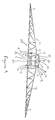
- Figures 1 to 3 show the basic types of known (prior art) boom adjustments that can be made to adjust the position/height of the boom over a target (whether ground, foliage or other applicable target).
- the function of the roll control system is to control a roll position of a boom rotatably coupled to a support frame, the "roll" position referring to a clockwise or counterclockwise rotation of the boom relative to the support frame.
- a sprayer 1 including a sprayer frame 2 and a sprayer tank 3 which, in this embodiment, are supported by wheels 4 allowing for the forward movement of the sprayer (but it is to be noted that in another embodiment the sprayer could, instead, be a cart which is towed by a self-propelled unit such as a tractor).
- a parallel linkage 5 and a main boom hydraulic lift cylinder 6 attach at one end thereof to the sprayer frame 2 and at the opposite end thereof to a boom support frame 7.
- the overall boom height adjustment illustrated by Figure 1 is performed by adjusting the lift cylinder 6 so as to cause it to lift (or lower) the boom support frame 7 and thereby adjust the height of the entire boom of the sprayer.
- An alternative means to achieve this vertical adjustment may be to instead use vertical sliding rails. It is to be noted, however, that this boom height adjustment is not relevant to the invention claimed herein.
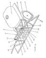
- Each of a roll frame 8 and a center boom frame 9 are coupled to the boom support frame 7 to permit clockwise or counterclockwise rotation relative thereto. This is done by a pivot pin 10 which provides a pivotal attachment to allow for rotational movement of the center boom frame 9.
- the roll frame 8 is also pivotally attached by pin 10 and is able to move rotationally (i.e. independent of any rotational movement by the center boom frame 9).
- the roll frame 8 is a rigid structure (made of steel in this embodiment) and is connected to the boom support frame 7 with a roll hydraulic cylinder 11. As the roll cylinder 11 extends (or retracts) it causes the roll frame 8 to rotate in a counterclockwise (or clockwise) direction.
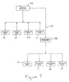
- the boom roll control system is provided in this embodiment by distance measurement devices 14, 17 and 21 mounted as shown and comprising ultrasonic sound echo sensors, a controller in the form of a microprocessor 25 (shown in Figure 7 but not shown in Figures 4-6), a roll hydraulic cylinder 11 and its associated operating valve (within valve bank 26), for rotating the boom (causing a roll).
- the controller 25 receives and processes distance measurement information signals from the devices 14, 17 and 21 and produces therefrom a roll control signal 27 configured to drive the valve within valve bank 26 which operates the roll hydraulic cylinder 11 (i.e. causes its extension member to move in or out), as appropriate, to control the roll of the boom and, thus, in turn, assist in controlling the height of the boom along its length over the spray target.
- Figures 4 and 5 show the layout of distance measurement devices (sensors) in the illustrated embodiment.
- Wing section position measuring apparatus is provided by left and right wing sensors 14, 17.
- Left wing sensor 14 produces a left wing signal correlating to the distance from the sensor 14 to a reference position (being shown as ground in the drawings to represent the spray target) and this distance represents the height of the left wing section 15.
- this wing-to-ground distance measurement is also used by the controller 25 to control the height of the left wing 15 by means of the left wing cylinder 16 (and, similarly, the output signal of right wing sensor 17 is used to control the height of the right wing section 18 by means of the right wing cylinder 19).
- a center boom sensor 20 produces a signal which correlates to the distance from the sensor 20 to the ground and this distance represents the height of the center boom 9.
- this boom-to-ground measurement is used by the controller 25 to control the height of the entire boom (i.e. by moving the boom support frame 7 and center boom frame 9 attached thereto to which the wings are attached) by means of a main boom lift cylinder 6.
- wing tip and boom height control features are identified herein for purposes of information only, however, and it is to be understood that they are not a part of the roll control system of the present invention.
- the distance measurement device 21 provides to the controller 25 dynamic distance measurement information that is associated with the roll action of the boom at the time the measurement is produced.
- an ultrasonic sound echo sensor 21 is used to measure the distance between the sensor 21 and a boom roll reference being a fixed spring target 22 (referred to herein as the "spring target distance").
- the spring target distance measured by sensor 21 correlates to the extension of centering springs 12 and, in turn, to the roll action of the boom.
- this spring target measurement is used in combination with the two wing sensor readings to form the basis of the roll control system of this invention as claimed herein.
- valves of the valve bank 26 connect to the hydraulic cylinders through hoses and operate (i.e. open) independently of each other under either the control of the controller 25 or a manual override mechanism (not shown in the drawings, but such override mechanisms being well known and typically provided for safety purposes).
- Each valve in the valve bank 26 functions to control its associated cylinder i.e.
- a roll cylinder valve controls the roll hydraulic cylinder
- a right wing hydraulic valve controls a hydraulic cylinder for the right wing of the boom, etc.
- proportional valves were selected for use, whereby the flow of oil to the hydraulic cylinder associated with each valve is proportionally controlled in accordance with the control signal fed from the controller 25 to that valve.
- the sensor 21 comprises an ultrasonic sound transducer for transmission and reception, as known in the art (alternatively, a separate transmitter and receiver may be used).
- the sensor 21 also comprises processing means, in the form of a microprocessor, configured for processing a received ultrasonic sound echo to filter out noise and other error-inducing information and for converting the filtered sound echo to a numerical value (e.g. x millimeters).
- Communications circuitry configured for communicating that value to the controller 25 is also provided by the sensor 21.
- the controller 25 selected for use comprises a microprocessor having an 8051 architecture.
- the reader will understand that numerous other specific controllers could also be appropriately configured and used to implement the invention, one general category of such alternative devices being programmable logic controllers (PLC's) which are well known to persons skilled in the art of control systems.
- PLC's programmable logic controllers
- the functions performed by the controller 25 include receiving and processing distance information from the sensors (e.g.
- the roll distance sensor 21 and the left and right distance sensors 14, 17 optionally providing an operator interface permitting an operator to set the system mode as automatic or manual (but this functionality may instead be configured separately from the controller 25, according to the chosen design), processing an algorithm in accordance with the invention to determine an output roll control signal and valve drivers for transmitting the roll control signal to the associated roll valve in valve bank 26.
- the controller 25 performs calculations based on the distance measurement information signals generated by the roll sensor 21 and left and right wing sensors 14, 17 and, in the result, a boom roll control error value (Erc) is calculated, based upon a combination of a wing section differential value (Ew) and a boom roll value (Es) (alternately referred to herein, specifically in Figure 8, as the wing roll error (Ew) and spring roll error (Es), respectively).
- the boom roll control error (Erc) is used by the controller 25 to calculate cylinder extension magnitude and direction control signals to drive the hydraulic valves 26 and operate the roll cylinder 11 according to the controller's calculations.
- the microprocessor 25 calculates a boom roll value (Es) equal to the measured spring target distance (ST) minus a set point height (SP_S), whereby the set point height is a reference target distance representing a reference roll position for the boom. It also calculates a wing section differential value (Ew) equal to one-half of the difference between the left wing-to-ground distance measurement (LW) and the right wing-to-ground distance measurement (RW).
- Es boom roll value
- SP_S set point height
- Each of the boom roll (Es) and wing section differential (Ew) values are scaled, by scaling factors (WSF and SSF, respectively), being a number which is typically less than 1, to produce scaled boom roll and wing section differential values (Es', Ew').
- scaling factors are used to determine the responsiveness of the control action and the specific values to be assigned to these scaling factors will be different for any given implementation of this invention, depending upon the boom dimensions and other dynamics of the particular equipment (e.g. sprayer) used for such implementation.
- standard control theory and scale factor testing is to be used for a given implementation in order to optimize the performance of the controller 25.
- a roll control error value (Erc) equal to the sum of the scaled boom roll and wing section differential values (Es' + Ew') is then calculated by the controller 25.
- the absolute value of the roll control error value i.e. to remove the roll direction information
- Dbrc roll control error deadband value
- the controller 25 produces a control signal from the roll control error value calculated to drive the roll cylinder valve of the valve bank 26 and adjust the roll cylinder 11 to control the roll action of the boom in accordance with the calculations of the controller 25.
- the roll control error value (Erc) is not more than the roll control error deadband value (Dbrc) it is set to zero and no adjustment is made to the roll action of the boom.
- the purpose for applying this deadband comparison is to ensure that an equilibrium point can be achieved by the control system whereby the control action ceases (i.e. at which the control signal 27 becomes inactive). Without such facilitation of an equilibrium point the control system would be subject to greater wear.
- the invention provides an active, intelligent roll control system for suspended booms having substantially improved performance over the basic known height control systems, the term "suspended boom" herein referring to a boom configuration in which the boom has no direct contact with the ground.
- this combination of height and roll control can be generally applied to any agricultural, industrial or construction equipment that utilizes both height and roll controls.
- the boom roll mechanism is provided by a roll frame 8 with a roll cylinder 11 coupling it to the boom support frame and springs 12 and damper 13 coupling it to the center boom 9.
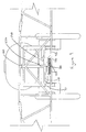
- alternative roll mechanisms may be appropriately designed for use in any given application (i.e. instead of that shown by Figures 4-6).
- Figures 9 One example of such an alternative is shown by Figures 9 in which the roll of the boom is controlled by means of a horizontally extending roll cylinder 110 and a roll bracket 80, whereby the roll bracket 80 takes the place of the roll frame 8 of the embodiment of Figures 4-6.
- this alternate embodiment controls the boom roll in similar manner to the boom roll mechanism shown in Figures 4-6.
- a pivot pin 100 couples a boom support frame 70 to a center boom frame 90 and a roll sensor 210 measures the distance to a spring target 220.
- the roll bracket 80 is connected to the boom support frame 70 with the roll hydraulic cylinder 110 which, when extended and retracted causes the roll bracket 80 to slide on a shaft (not shown) which acts as a guide for compression springs 120 coupled to the center boom frame 90.
- the roll bracket 80 couples together the cylinder 110, a damper 130, both springs 120 and a spring target 220.
- the sensor 21 can also be used to determine the relative position of the center boom 9 to the boom support frame 7, whereby the position of a second target 23 mounted to the boom support frame 7 (see Figure 5) is also measured by sensor 21.
- a second target 23 mounted to the boom support frame 7 see Figure 5
- sensor 21 By using an ultrasonic echo sensor for sensor 21 only that (one) sensor is needed to do this but a separate distance or angular sensor could also be used.
- the sensor 21 can also be used to determine the height of the center boom 9 so as to eliminate the need for the separate center boom height sensor 20.
- a boom support frame target distance (REF) plus an offset (as shown) are subtracted from a sensor-measured distance to the spray target (ground) to determine the center boom height.
Landscapes
- Life Sciences & Earth Sciences (AREA)
- Engineering & Computer Science (AREA)
- Insects & Arthropods (AREA)
- Pest Control & Pesticides (AREA)
- Wood Science & Technology (AREA)
- Zoology (AREA)
- Environmental Sciences (AREA)
- Catching Or Destruction (AREA)
- Lifting Devices For Agricultural Implements (AREA)
- Special Spraying Apparatus (AREA)
Applications Claiming Priority (2)
| Application Number | Priority Date | Filing Date | Title |
|---|---|---|---|
| CA002418610A CA2418610C (en) | 2003-02-10 | 2003-02-10 | Roll control system and method for a suspended boom |
| CA2418610 | 2003-02-10 |
Publications (2)
| Publication Number | Publication Date |
|---|---|
| EP1444894A1 true EP1444894A1 (de) | 2004-08-11 |
| EP1444894B1 EP1444894B1 (de) | 2007-01-17 |
Family
ID=32601885
Family Applications (1)
| Application Number | Title | Priority Date | Filing Date |
|---|---|---|---|
| EP04100479A Expired - Lifetime EP1444894B1 (de) | 2003-02-10 | 2004-02-09 | System und Verfahren für die Rollregelung eines aufgehängten Gestänges |
Country Status (5)
| Country | Link |
|---|---|
| EP (1) | EP1444894B1 (de) |
| CA (1) | CA2418610C (de) |
| DE (1) | DE602004004297T2 (de) |
| DK (1) | DK1444894T3 (de) |
| ES (1) | ES2278275T3 (de) |
Cited By (25)
| Publication number | Priority date | Publication date | Assignee | Title |
|---|---|---|---|---|
| US7913930B2 (en) | 2007-11-28 | 2011-03-29 | John Deere Fabriek Horst B.V. | Spray boom with dampening device |
| FR2965453A1 (fr) * | 2010-10-05 | 2012-04-06 | Exel Ind | Engin agricole de pulverisation et procede de pulverisation d'un liquide phytosanitaire sur un terrain cultive au moyen d'un tel engin |
| FR2965454A1 (fr) * | 2010-10-05 | 2012-04-06 | Exel Ind | Engin agricole de pulverisation et procede de pulverisation d'un liquide phytosanitaire sur un terrain cultive au moyen d'un tel engin |
| EP2446724A1 (de) * | 2010-10-29 | 2012-05-02 | John Deere Fabriek Horst B.V. | Landwirtschaftliche Maschine |
| WO2015067804A1 (de) * | 2013-11-10 | 2015-05-14 | Horsch Leeb Application Systems Gmbh | Vorrichtung zum ausbringen von flüssigen und/oder festen wirkstoffen und verfahren zur steuerung einer solchen vorrichtung |
| EP2936980A1 (de) * | 2014-04-23 | 2015-10-28 | Robert Bosch Gmbh | Feldspritze |
| EP2959763A1 (de) * | 2014-06-24 | 2015-12-30 | Harry Højvang Sørensen | Spritzgestänge mit klappflügel und feldspritze oder schlammwagen mit einer solchen spritzgestänge |
| DE102015101032A1 (de) | 2015-01-26 | 2016-07-28 | Amazonen-Werke H. Dreyer Gmbh & Co. Kg | Landwirtschaftliche Maschine und Regelungsverfahren |
| DE102015104690A1 (de) | 2015-03-27 | 2016-09-29 | Amazonen-Werke H. Dreyer Gmbh & Co. Kg | Landwirtschaftliche Maschine und Sicherheitsverfahren |
| EP3007553B1 (de) | 2013-09-18 | 2017-03-01 | HORSCH LEEB Application Systems GmbH | Vorrichtung zum ausbringen von flüssigen und/oder festen wirkstoffen und verfahren zur steuerung einer solchen vorrichtung |
| EP3165073A1 (de) | 2015-11-06 | 2017-05-10 | Amazonen-Werke H. Dreyer GmbH & Co. KG | Regel- oder steuersystem, landwirtschaftliche maschine |
| EP3165091A1 (de) | 2015-11-06 | 2017-05-10 | Amazonen-Werke H. Dreyer GmbH & Co. KG | Regel- oder steuersystem für eine landwirtschaftliche maschine |
| EP2591657B1 (de) | 2011-11-08 | 2017-06-28 | HORSCH LEEB Application Systems GmbH | Fahrbare Vorrichtung zum Ausbringen von flüssigen und/oder festen Wirkstoffen und Verfahren zur Steuerung der Vorrichtung |
| WO2018162539A1 (de) * | 2017-03-08 | 2018-09-13 | Amazonen-Werke H. Dreyer Gmbh & Co. Kg | Regelsystem, landwirtschaftliches nutzfahrzeug und verfahren zur regelung eines landwirtschaftlichen nutzfahrzeuges |
| EP3501274A1 (de) * | 2017-12-21 | 2019-06-26 | Kverneland Group Nieuw-Vennep BV | Auslegermontageanordnung und verfahren zur steuerung des betriebs einer auslegermontageanordnung |
| US10561061B2 (en) | 2015-03-02 | 2020-02-18 | Horsch Leeb Application Systems Gmbh | Device for spreading liquid and/or solid active agents and method for controlling such a device |
| EP3035795B1 (de) | 2013-10-14 | 2020-11-18 | HORSCH LEEB Application Systems GmbH | Feldspritze zum ausbringen von flüssigen und/oder festen wirkstoffen und regelung zur steuerung derselben |
| EP3753407A1 (de) | 2019-05-27 | 2020-12-23 | Amazonen-Werke H. Dreyer GmbH & Co. KG | Landwirtschaftliches gerät mit verbesserter neigungsregelung |
| EP3766327A1 (de) * | 2019-07-15 | 2021-01-20 | Kverneland Group Kerteminde A/S | Arbeitswerkzeug |
| CN113016756A (zh) * | 2021-02-22 | 2021-06-25 | 江苏大学 | 一种基于多源信息融合的喷杆对地高度实时监测系统及方法 |
| EP3874946A1 (de) * | 2020-03-04 | 2021-09-08 | Deere & Company | System zum verbinden eines hängenden auslegerrahmens mit einem festen rahmen und fahrzeug damit |
| EP3874947A1 (de) * | 2020-03-04 | 2021-09-08 | Deere & Company | Positionierungssystem für mittelrahmen und landwirtschaftliches sprühfahrzeug damit |
| CN114651804A (zh) * | 2022-04-12 | 2022-06-24 | 重庆梦马致新科技有限公司 | 喷药车 |
| EP4212018A1 (de) | 2022-01-14 | 2023-07-19 | Amazonen-Werke H. Dreyer SE & Co. KG | Landwirtschaftliches gerät mit verbesserter neigungsregelung |
| DE202022002936U1 (de) | 2022-01-14 | 2024-01-30 | Amazonen-Werke H. Dreyer SE & Co. KG | Landwirtschaftliches Gerät mit verbesserter Neigungsregelung |
Families Citing this family (3)
| Publication number | Priority date | Publication date | Assignee | Title |
|---|---|---|---|---|
| ES2333767B1 (es) * | 2009-09-23 | 2010-10-13 | Amp Sprayers, S.L. | Sistema de sujecion de la estructura de brazos en maquinas fumigadoras agricolas. |
| DE102015119145A1 (de) * | 2015-11-06 | 2017-05-11 | Amazonen-Werke H. Dreyer Gmbh & Co. Kg | Regel- und/oder Steuersystem für eine landwirtschaftliche Maschine |
| DE102019130576A1 (de) * | 2019-11-13 | 2021-05-20 | Amazonen-Werke H. Dreyer Gmbh & Co. Kg | Verfahren zum Erfassen des Abstands eines Gestänges zu einer landwirtschaftlichen Nutzfläche und/oder deren Pflanzenbestand |
Citations (7)
| Publication number | Priority date | Publication date | Assignee | Title |
|---|---|---|---|---|
| EP0157592A2 (de) * | 1984-03-27 | 1985-10-09 | Btg International Limited | Spritzgestänge |
| FR2562378A1 (fr) * | 1984-04-05 | 1985-10-11 | Nodet Gougis | Dispositif de regulation automatique de l'attitude d'un accessoire de machine agricole tel qu'une rampe de pulverisation |
| DE4140254A1 (de) * | 1991-10-22 | 1993-06-09 | Gerd E. F. 8608 Memmelsdorf De Steffen | Ultraschallgefuehrte spritze fuer die landwirtschaft |
| EP0922385A1 (de) * | 1997-12-10 | 1999-06-16 | Amazonen-Werke H. Dreyer GmbH & Co. KG | Landwirtschaftliche Maschine zum Verteilen von Material, vorzugsweise Feldspritze |
| FR2795913A1 (fr) * | 1999-07-09 | 2001-01-12 | Michel Barrau | Systeme electronique d'autocontrole du niveau d'inclinaison d'une rampe de pulverisation |
| EP1167095A1 (de) * | 2000-06-26 | 2002-01-02 | K.U. Leuven Research & Development | Verfahren und Vorrichtung zur Steuerung und Stabilisierung einer Bewegung |
| JP2002034422A (ja) * | 2000-07-27 | 2002-02-05 | Iseki & Co Ltd | 薬剤散布装置の水平制御装置 |
-
2003
- 2003-02-10 CA CA002418610A patent/CA2418610C/en not_active Expired - Lifetime
-
2004
- 2004-02-09 EP EP04100479A patent/EP1444894B1/de not_active Expired - Lifetime
- 2004-02-09 DE DE602004004297T patent/DE602004004297T2/de not_active Expired - Lifetime
- 2004-02-09 DK DK04100479T patent/DK1444894T3/da active
- 2004-02-09 ES ES04100479T patent/ES2278275T3/es not_active Expired - Lifetime
Patent Citations (7)
| Publication number | Priority date | Publication date | Assignee | Title |
|---|---|---|---|---|
| EP0157592A2 (de) * | 1984-03-27 | 1985-10-09 | Btg International Limited | Spritzgestänge |
| FR2562378A1 (fr) * | 1984-04-05 | 1985-10-11 | Nodet Gougis | Dispositif de regulation automatique de l'attitude d'un accessoire de machine agricole tel qu'une rampe de pulverisation |
| DE4140254A1 (de) * | 1991-10-22 | 1993-06-09 | Gerd E. F. 8608 Memmelsdorf De Steffen | Ultraschallgefuehrte spritze fuer die landwirtschaft |
| EP0922385A1 (de) * | 1997-12-10 | 1999-06-16 | Amazonen-Werke H. Dreyer GmbH & Co. KG | Landwirtschaftliche Maschine zum Verteilen von Material, vorzugsweise Feldspritze |
| FR2795913A1 (fr) * | 1999-07-09 | 2001-01-12 | Michel Barrau | Systeme electronique d'autocontrole du niveau d'inclinaison d'une rampe de pulverisation |
| EP1167095A1 (de) * | 2000-06-26 | 2002-01-02 | K.U. Leuven Research & Development | Verfahren und Vorrichtung zur Steuerung und Stabilisierung einer Bewegung |
| JP2002034422A (ja) * | 2000-07-27 | 2002-02-05 | Iseki & Co Ltd | 薬剤散布装置の水平制御装置 |
Non-Patent Citations (1)
| Title |
|---|
| PATENT ABSTRACTS OF JAPAN vol. 2002, no. 06 4 June 2002 (2002-06-04) * |
Cited By (51)
| Publication number | Priority date | Publication date | Assignee | Title |
|---|---|---|---|---|
| US7913930B2 (en) | 2007-11-28 | 2011-03-29 | John Deere Fabriek Horst B.V. | Spray boom with dampening device |
| FR2965453A1 (fr) * | 2010-10-05 | 2012-04-06 | Exel Ind | Engin agricole de pulverisation et procede de pulverisation d'un liquide phytosanitaire sur un terrain cultive au moyen d'un tel engin |
| FR2965454A1 (fr) * | 2010-10-05 | 2012-04-06 | Exel Ind | Engin agricole de pulverisation et procede de pulverisation d'un liquide phytosanitaire sur un terrain cultive au moyen d'un tel engin |
| WO2012045964A1 (fr) * | 2010-10-05 | 2012-04-12 | Exel Industries | Engin agricole de pulvérisation et procédé de pulvérisation d'un liquide phytosanitaire sur un terrain cultivé au moyen d'un tel engin |
| WO2012045963A1 (fr) * | 2010-10-05 | 2012-04-12 | Exel Industries | Engin agricole de pulvérisation et procède de pulvérisation d'un liquide phytosanitaire sur un terrain cultive au moyen d'un tel engin |
| EP2624685B1 (de) | 2010-10-05 | 2017-12-13 | Exel Industries | Landwirtschaftliche sprühmaschine und verfahren zum sprühen einer phytosanitären flüssigkeit auf mit einer derartigen maschine kultivierten boden |
| US9707882B2 (en) | 2010-10-05 | 2017-07-18 | Exel Industries | Agricultural spraying machine and method for spraying a phytosanitary liquid on land cultivated by means of such a machine |
| US10343585B2 (en) | 2010-10-05 | 2019-07-09 | Exel Industries | Agricultural spraying machine and method for spraying a phytosanitary liquid on land cultivated by means of such a machine |
| US9565847B2 (en) | 2010-10-05 | 2017-02-14 | Exel Industries | Agricultural spraying machine and method for spraying a phytosanitary liquid on land cultivated by means of such a machine |
| EA022079B1 (ru) * | 2010-10-05 | 2015-10-30 | Эксель Эндюстри | Сельскохозяйственный распылительный агрегат и способ распыления фитосанитарной жидкости на участке, обрабатываемом при помощи такого агрегата |
| EA024582B1 (ru) * | 2010-10-05 | 2016-09-30 | Эксель Эндюстри | Сельскохозяйственный распылительный агрегат и способ управления таким агрегатом при распылении фитосанитарной жидкости |
| EP2446724A1 (de) * | 2010-10-29 | 2012-05-02 | John Deere Fabriek Horst B.V. | Landwirtschaftliche Maschine |
| EP2591657B1 (de) | 2011-11-08 | 2017-06-28 | HORSCH LEEB Application Systems GmbH | Fahrbare Vorrichtung zum Ausbringen von flüssigen und/oder festen Wirkstoffen und Verfahren zur Steuerung der Vorrichtung |
| EP3007553B1 (de) | 2013-09-18 | 2017-03-01 | HORSCH LEEB Application Systems GmbH | Vorrichtung zum ausbringen von flüssigen und/oder festen wirkstoffen und verfahren zur steuerung einer solchen vorrichtung |
| US10470361B2 (en) | 2013-09-18 | 2019-11-12 | Horsch Leeb Application Systems Gmbh | Device for discharging fluid and/or solid active materials and method for controlling such a device |
| EP3183963B1 (de) | 2013-09-18 | 2018-05-16 | HORSCH LEEB Application Systems GmbH | Vorrichtung zum ausbringen von flüssigen und/oder festen wirkstoffen und verfahren zur steuerung einer solchen vorrichtung |
| EP3035795B1 (de) | 2013-10-14 | 2020-11-18 | HORSCH LEEB Application Systems GmbH | Feldspritze zum ausbringen von flüssigen und/oder festen wirkstoffen und regelung zur steuerung derselben |
| EP4018801A1 (de) * | 2013-11-10 | 2022-06-29 | HORSCH LEEB Application Systems GmbH | Vorrichtung zum ausbringen von flüssigen und/oder festen wirkstoffen und verfahren zur steuerung einer solchen vorrichtung |
| US10244747B2 (en) | 2013-11-10 | 2019-04-02 | Horsch Leeb Application Systems Gmbh | Apparatus and method for discharging liquid and/or solid active substances |
| WO2015067804A1 (de) * | 2013-11-10 | 2015-05-14 | Horsch Leeb Application Systems Gmbh | Vorrichtung zum ausbringen von flüssigen und/oder festen wirkstoffen und verfahren zur steuerung einer solchen vorrichtung |
| DE102014207595A1 (de) * | 2014-04-23 | 2015-10-29 | Robert Bosch Gmbh | Feldspritze |
| EP2936980A1 (de) * | 2014-04-23 | 2015-10-28 | Robert Bosch Gmbh | Feldspritze |
| EP2959763A1 (de) * | 2014-06-24 | 2015-12-30 | Harry Højvang Sørensen | Spritzgestänge mit klappflügel und feldspritze oder schlammwagen mit einer solchen spritzgestänge |
| DE102015101032A1 (de) | 2015-01-26 | 2016-07-28 | Amazonen-Werke H. Dreyer Gmbh & Co. Kg | Landwirtschaftliche Maschine und Regelungsverfahren |
| US10750734B2 (en) | 2015-01-26 | 2020-08-25 | Amazonen Werke H. Dreyer Gmbh & Co. Kg | Agricultural machine and control method |
| US10561061B2 (en) | 2015-03-02 | 2020-02-18 | Horsch Leeb Application Systems Gmbh | Device for spreading liquid and/or solid active agents and method for controlling such a device |
| DE102015104690A1 (de) | 2015-03-27 | 2016-09-29 | Amazonen-Werke H. Dreyer Gmbh & Co. Kg | Landwirtschaftliche Maschine und Sicherheitsverfahren |
| EP3075246A1 (de) | 2015-03-27 | 2016-10-05 | Amazonen-Werke H. Dreyer GmbH & Co. KG | Landwirtschaftliche maschine und sicherheitsverfahren |
| EP3165073A1 (de) | 2015-11-06 | 2017-05-10 | Amazonen-Werke H. Dreyer GmbH & Co. KG | Regel- oder steuersystem, landwirtschaftliche maschine |
| DE102015119078A1 (de) | 2015-11-06 | 2017-05-11 | Amazonen-Werke H. Dreyer Gmbh & Co. Kg | Regel- oder Steuersystem für eine landwirtschaftliche Maschine |
| EP3165091A1 (de) | 2015-11-06 | 2017-05-10 | Amazonen-Werke H. Dreyer GmbH & Co. KG | Regel- oder steuersystem für eine landwirtschaftliche maschine |
| DE102015119073A1 (de) | 2015-11-06 | 2017-05-11 | Amazonen-Werke H. Dreyer Gmbh & Co. Kg | Regel- oder Steuersystem, landwirtschaftliche Maschine |
| WO2018162539A1 (de) * | 2017-03-08 | 2018-09-13 | Amazonen-Werke H. Dreyer Gmbh & Co. Kg | Regelsystem, landwirtschaftliches nutzfahrzeug und verfahren zur regelung eines landwirtschaftlichen nutzfahrzeuges |
| US11856943B2 (en) | 2017-03-08 | 2024-01-02 | Amazonen-Werke H. Dreyer SE & Co. KG | Control system, agricultural utility vehicle and method for controlling an agricultural utility vehicle |
| US11447924B2 (en) | 2017-12-21 | 2022-09-20 | Kverneland Group Nieuw-Vennep B.V. | Boom mounting assembly and method for controlling operation of a boom mounting assembly |
| WO2019120953A1 (en) | 2017-12-21 | 2019-06-27 | Kverneland Group Nieuw-Vennep B.V. | Boom mounting assembly and method for controlling operation of a boom mounting assembly |
| EP3501274A1 (de) * | 2017-12-21 | 2019-06-26 | Kverneland Group Nieuw-Vennep BV | Auslegermontageanordnung und verfahren zur steuerung des betriebs einer auslegermontageanordnung |
| AU2018386906B2 (en) * | 2017-12-21 | 2022-01-06 | Kverneland Group Nieuw-Vennep B.V. | Boom mounting assembly and method for controlling operation of a boom mounting assembly |
| RU2762937C1 (ru) * | 2017-12-21 | 2021-12-24 | Квернеланд Груп Ньив-Веннеп Б.В. | Узел установки штанги и способ управления работой узла установки штанги |
| EP3753407A1 (de) | 2019-05-27 | 2020-12-23 | Amazonen-Werke H. Dreyer GmbH & Co. KG | Landwirtschaftliches gerät mit verbesserter neigungsregelung |
| EP3766327A1 (de) * | 2019-07-15 | 2021-01-20 | Kverneland Group Kerteminde A/S | Arbeitswerkzeug |
| EP3874947A1 (de) * | 2020-03-04 | 2021-09-08 | Deere & Company | Positionierungssystem für mittelrahmen und landwirtschaftliches sprühfahrzeug damit |
| EP3874946A1 (de) * | 2020-03-04 | 2021-09-08 | Deere & Company | System zum verbinden eines hängenden auslegerrahmens mit einem festen rahmen und fahrzeug damit |
| US11980181B2 (en) | 2020-03-04 | 2024-05-14 | Deere & Company | Agricultural sprayer active boom center frame positioning system |
| US11980180B2 (en) | 2020-03-04 | 2024-05-14 | Deere & Company | Pendulum boom suspension |
| WO2022174510A1 (zh) * | 2021-02-22 | 2022-08-25 | 江苏大学 | 一种基于多源信息融合的喷杆对地高度实时监测系统及方法 |
| CN113016756A (zh) * | 2021-02-22 | 2021-06-25 | 江苏大学 | 一种基于多源信息融合的喷杆对地高度实时监测系统及方法 |
| EP4212018A1 (de) | 2022-01-14 | 2023-07-19 | Amazonen-Werke H. Dreyer SE & Co. KG | Landwirtschaftliches gerät mit verbesserter neigungsregelung |
| DE102022100808A1 (de) | 2022-01-14 | 2023-07-20 | Amazonen-Werke H. Dreyer SE & Co. KG | Landwirtschaftliches Gerät mit verbesserter Neigungsregelung |
| DE202022002936U1 (de) | 2022-01-14 | 2024-01-30 | Amazonen-Werke H. Dreyer SE & Co. KG | Landwirtschaftliches Gerät mit verbesserter Neigungsregelung |
| CN114651804A (zh) * | 2022-04-12 | 2022-06-24 | 重庆梦马致新科技有限公司 | 喷药车 |
Also Published As
| Publication number | Publication date |
|---|---|
| DE602004004297T2 (de) | 2007-11-22 |
| CA2418610A1 (en) | 2004-08-10 |
| ES2278275T3 (es) | 2007-08-01 |
| DE602004004297D1 (de) | 2007-03-08 |
| CA2418610C (en) | 2005-11-15 |
| EP1444894B1 (de) | 2007-01-17 |
| DK1444894T3 (da) | 2007-05-21 |
Similar Documents
| Publication | Publication Date | Title |
|---|---|---|
| US6834223B2 (en) | Roll control system and method for a suspended boom | |
| CA2418610C (en) | Roll control system and method for a suspended boom | |
| DK2591657T3 (en) | MOVING DEVICE FOR SPREADING FLUID AND / OR SUBSTANCES AND METHOD OF MANAGING SAME DEVICE | |
| EP3546416B1 (de) | Selbstfahrende gelenkarbeitsmaschine | |
| EP3183963B1 (de) | Vorrichtung zum ausbringen von flüssigen und/oder festen wirkstoffen und verfahren zur steuerung einer solchen vorrichtung | |
| EP3103927B1 (de) | Automatisiertes streichblech-zugkraftsteuerungssystem und verfahren | |
| US20170245434A1 (en) | Automatic determination of the control unit parameters of an arrangement to control an actuator for the adjustment of an adjustable element of an agricultural machine | |
| EP1880057B1 (de) | Fertiger zum bodenseitigen einbau von schichten für strassen od.dgl. | |
| CN107787630B (zh) | 用于影响农用附加装置的位置的装置 | |
| US7721813B2 (en) | Implement/hitch draft control using hitch cylinder pressure as load feedback | |
| DE10101570A1 (de) | Großmanipulator mit Schwingungsdämpfung | |
| CN104541636A (zh) | 一种拖拉机液压悬挂位置调节的电控装置及方法 | |
| US11122754B2 (en) | Implement optimization by automated adjustments | |
| US11696523B2 (en) | System and method for hydraulically leveling a multi-wing agricultural implement | |
| CN104920327B (zh) | 一种喷杆平衡自动调节装置 | |
| US11751556B2 (en) | System and method for actuating a boom assembly of an agricultural sprayer | |
| EP3788854B1 (de) | Verfahren zur steuerung der neigung eines landwirtschaftlichen anbaugeräts und steuerungssystem dafür | |
| US11980181B2 (en) | Agricultural sprayer active boom center frame positioning system | |
| EP0722654B1 (de) | Fahrbares Ausleger-Arbeitsgerät für Unterhaltungsarbeiten im Strassenbereich | |
| CA3085780A1 (en) | Method for operating an agricultural machine and agricultural machine | |
| US20220264859A1 (en) | Agricultural machine having improved suspension | |
| DE10131559A1 (de) | Vorrichtung zur Bodendruckentlastung von am Erdboden arbeitenden Arbeitsgeräten | |
| US20210062463A1 (en) | Variable float and variable blade impact | |
| CN110679213A (zh) | 一种旋耕机自动调平系统及其自动调平方法 | |
| US20220225602A1 (en) | Control and/or regulating system for an agricultural device |
Legal Events
| Date | Code | Title | Description |
|---|---|---|---|
| PUAI | Public reference made under article 153(3) epc to a published international application that has entered the european phase |
Free format text: ORIGINAL CODE: 0009012 |
|
| AK | Designated contracting states |
Kind code of ref document: A1 Designated state(s): AT BE BG CH CY CZ DE DK EE ES FI FR GB GR HU IE IT LI LU MC NL PT RO SE SI SK TR |
|
| AX | Request for extension of the european patent |
Extension state: AL LT LV MK |
|
| 17P | Request for examination filed |
Effective date: 20050127 |
|
| AKX | Designation fees paid |
Designated state(s): AT BE BG CH CY CZ DE DK EE ES FI FR GB GR HU IE IT LI LU MC NL PT RO SE SI SK TR |
|
| 17Q | First examination report despatched |
Effective date: 20050520 |
|
| GRAP | Despatch of communication of intention to grant a patent |
Free format text: ORIGINAL CODE: EPIDOSNIGR1 |
|
| GRAS | Grant fee paid |
Free format text: ORIGINAL CODE: EPIDOSNIGR3 |
|
| GRAA | (expected) grant |
Free format text: ORIGINAL CODE: 0009210 |
|
| AK | Designated contracting states |
Kind code of ref document: B1 Designated state(s): AT BE BG CH CY CZ DE DK EE ES FI FR GB GR HU IE IT LI LU MC NL PT RO SE SI SK TR |
|
| PG25 | Lapsed in a contracting state [announced via postgrant information from national office to epo] |
Ref country code: CH Free format text: LAPSE BECAUSE OF FAILURE TO SUBMIT A TRANSLATION OF THE DESCRIPTION OR TO PAY THE FEE WITHIN THE PRESCRIBED TIME-LIMIT Effective date: 20070117 Ref country code: LI Free format text: LAPSE BECAUSE OF FAILURE TO SUBMIT A TRANSLATION OF THE DESCRIPTION OR TO PAY THE FEE WITHIN THE PRESCRIBED TIME-LIMIT Effective date: 20070117 Ref country code: AT Free format text: LAPSE BECAUSE OF FAILURE TO SUBMIT A TRANSLATION OF THE DESCRIPTION OR TO PAY THE FEE WITHIN THE PRESCRIBED TIME-LIMIT Effective date: 20070117 Ref country code: SI Free format text: LAPSE BECAUSE OF FAILURE TO SUBMIT A TRANSLATION OF THE DESCRIPTION OR TO PAY THE FEE WITHIN THE PRESCRIBED TIME-LIMIT Effective date: 20070117 Ref country code: FI Free format text: LAPSE BECAUSE OF FAILURE TO SUBMIT A TRANSLATION OF THE DESCRIPTION OR TO PAY THE FEE WITHIN THE PRESCRIBED TIME-LIMIT Effective date: 20070117 |
|
| REG | Reference to a national code |
Ref country code: GB Ref legal event code: FG4D |
|
| REG | Reference to a national code |
Ref country code: CH Ref legal event code: EP |
|
| PG25 | Lapsed in a contracting state [announced via postgrant information from national office to epo] |
Ref country code: MC Free format text: LAPSE BECAUSE OF NON-PAYMENT OF DUE FEES Effective date: 20070228 |
|
| REG | Reference to a national code |
Ref country code: IE Ref legal event code: FG4D |
|
| REF | Corresponds to: |
Ref document number: 602004004297 Country of ref document: DE Date of ref document: 20070308 Kind code of ref document: P |
|
| PG25 | Lapsed in a contracting state [announced via postgrant information from national office to epo] |
Ref country code: SE Free format text: LAPSE BECAUSE OF FAILURE TO SUBMIT A TRANSLATION OF THE DESCRIPTION OR TO PAY THE FEE WITHIN THE PRESCRIBED TIME-LIMIT Effective date: 20070417 |
|
| PG25 | Lapsed in a contracting state [announced via postgrant information from national office to epo] |
Ref country code: BG Free format text: LAPSE BECAUSE OF FAILURE TO SUBMIT A TRANSLATION OF THE DESCRIPTION OR TO PAY THE FEE WITHIN THE PRESCRIBED TIME-LIMIT Effective date: 20070418 |
|
| REG | Reference to a national code |
Ref country code: DK Ref legal event code: T3 |
|
| PGFP | Annual fee paid to national office [announced via postgrant information from national office to epo] |
Ref country code: IE Payment date: 20070528 Year of fee payment: 4 |
|
| PG25 | Lapsed in a contracting state [announced via postgrant information from national office to epo] |
Ref country code: PT Free format text: LAPSE BECAUSE OF FAILURE TO SUBMIT A TRANSLATION OF THE DESCRIPTION OR TO PAY THE FEE WITHIN THE PRESCRIBED TIME-LIMIT Effective date: 20070618 |
|
| REG | Reference to a national code |
Ref country code: CH Ref legal event code: PL |
|
| REG | Reference to a national code |
Ref country code: ES Ref legal event code: FG2A Ref document number: 2278275 Country of ref document: ES Kind code of ref document: T3 |
|
| ET | Fr: translation filed | ||
| PLBI | Opposition filed |
Free format text: ORIGINAL CODE: 0009260 |
|
| 26 | Opposition filed |
Opponent name: AMAZONEN-WERKE H. DREYER GMBH & CO. KG Effective date: 20071016 |
|
| PLAX | Notice of opposition and request to file observation + time limit sent |
Free format text: ORIGINAL CODE: EPIDOSNOBS2 |
|
| PG25 | Lapsed in a contracting state [announced via postgrant information from national office to epo] |
Ref country code: SK Free format text: LAPSE BECAUSE OF FAILURE TO SUBMIT A TRANSLATION OF THE DESCRIPTION OR TO PAY THE FEE WITHIN THE PRESCRIBED TIME-LIMIT Effective date: 20070117 |
|
| NLR1 | Nl: opposition has been filed with the epo |
Opponent name: AMAZONEN-WERKE H. DREYER GMBH & CO. KG |
|
| PG25 | Lapsed in a contracting state [announced via postgrant information from national office to epo] |
Ref country code: CZ Free format text: LAPSE BECAUSE OF FAILURE TO SUBMIT A TRANSLATION OF THE DESCRIPTION OR TO PAY THE FEE WITHIN THE PRESCRIBED TIME-LIMIT Effective date: 20070117 Ref country code: RO Free format text: LAPSE BECAUSE OF FAILURE TO SUBMIT A TRANSLATION OF THE DESCRIPTION OR TO PAY THE FEE WITHIN THE PRESCRIBED TIME-LIMIT Effective date: 20070117 Ref country code: BE Free format text: LAPSE BECAUSE OF FAILURE TO SUBMIT A TRANSLATION OF THE DESCRIPTION OR TO PAY THE FEE WITHIN THE PRESCRIBED TIME-LIMIT Effective date: 20070117 |
|
| PLAF | Information modified related to communication of a notice of opposition and request to file observations + time limit |
Free format text: ORIGINAL CODE: EPIDOSCOBS2 |
|
| PLBB | Reply of patent proprietor to notice(s) of opposition received |
Free format text: ORIGINAL CODE: EPIDOSNOBS3 |
|
| PG25 | Lapsed in a contracting state [announced via postgrant information from national office to epo] |
Ref country code: GR Free format text: LAPSE BECAUSE OF FAILURE TO SUBMIT A TRANSLATION OF THE DESCRIPTION OR TO PAY THE FEE WITHIN THE PRESCRIBED TIME-LIMIT Effective date: 20070418 |
|
| PLAB | Opposition data, opponent's data or that of the opponent's representative modified |
Free format text: ORIGINAL CODE: 0009299OPPO |
|
| PLAB | Opposition data, opponent's data or that of the opponent's representative modified |
Free format text: ORIGINAL CODE: 0009299OPPO |
|
| PLAB | Opposition data, opponent's data or that of the opponent's representative modified |
Free format text: ORIGINAL CODE: 0009299OPPO |
|
| R26 | Opposition filed (corrected) |
Opponent name: AMAZONEN-WERKE H. DREYER GMBH & CO. KG Effective date: 20071016 |
|
| R26 | Opposition filed (corrected) |
Opponent name: AMAZONEN-WERKE H. DREYER GMBH & CO. KG Effective date: 20071016 |
|
| R26 | Opposition filed (corrected) |
Opponent name: AMAZONEN-WERKE H. DREYER GMBH & CO. KG Effective date: 20071016 |
|
| NLR1 | Nl: opposition has been filed with the epo |
Opponent name: AMAZONEN-WERKE H. DREYER GMBH & CO. KG |
|
| NLR1 | Nl: opposition has been filed with the epo |
Opponent name: AMAZONEN-WERKE H. DREYER GMBH & CO. KG |
|
| PG25 | Lapsed in a contracting state [announced via postgrant information from national office to epo] |
Ref country code: IE Free format text: LAPSE BECAUSE OF NON-PAYMENT OF DUE FEES Effective date: 20080211 Ref country code: EE Free format text: LAPSE BECAUSE OF FAILURE TO SUBMIT A TRANSLATION OF THE DESCRIPTION OR TO PAY THE FEE WITHIN THE PRESCRIBED TIME-LIMIT Effective date: 20070117 |
|
| PG25 | Lapsed in a contracting state [announced via postgrant information from national office to epo] |
Ref country code: CY Free format text: LAPSE BECAUSE OF FAILURE TO SUBMIT A TRANSLATION OF THE DESCRIPTION OR TO PAY THE FEE WITHIN THE PRESCRIBED TIME-LIMIT Effective date: 20070117 |
|
| PG25 | Lapsed in a contracting state [announced via postgrant information from national office to epo] |
Ref country code: LU Free format text: LAPSE BECAUSE OF NON-PAYMENT OF DUE FEES Effective date: 20070209 |
|
| PG25 | Lapsed in a contracting state [announced via postgrant information from national office to epo] |
Ref country code: TR Free format text: LAPSE BECAUSE OF FAILURE TO SUBMIT A TRANSLATION OF THE DESCRIPTION OR TO PAY THE FEE WITHIN THE PRESCRIBED TIME-LIMIT Effective date: 20070117 Ref country code: HU Free format text: LAPSE BECAUSE OF FAILURE TO SUBMIT A TRANSLATION OF THE DESCRIPTION OR TO PAY THE FEE WITHIN THE PRESCRIBED TIME-LIMIT Effective date: 20070718 |
|
| PLCK | Communication despatched that opposition was rejected |
Free format text: ORIGINAL CODE: EPIDOSNREJ1 |
|
| APBM | Appeal reference recorded |
Free format text: ORIGINAL CODE: EPIDOSNREFNO |
|
| APBP | Date of receipt of notice of appeal recorded |
Free format text: ORIGINAL CODE: EPIDOSNNOA2O |
|
| APAH | Appeal reference modified |
Free format text: ORIGINAL CODE: EPIDOSCREFNO |
|
| APBQ | Date of receipt of statement of grounds of appeal recorded |
Free format text: ORIGINAL CODE: EPIDOSNNOA3O |
|
| REG | Reference to a national code |
Ref country code: DE Ref legal event code: R100 Ref document number: 602004004297 Country of ref document: DE |
|
| APBU | Appeal procedure closed |
Free format text: ORIGINAL CODE: EPIDOSNNOA9O |
|
| PLBN | Opposition rejected |
Free format text: ORIGINAL CODE: 0009273 |
|
| STAA | Information on the status of an ep patent application or granted ep patent |
Free format text: STATUS: OPPOSITION REJECTED |
|
| 27O | Opposition rejected |
Effective date: 20150220 |
|
| REG | Reference to a national code |
Ref country code: DE Ref legal event code: R100 Ref document number: 602004004297 Country of ref document: DE Effective date: 20150220 |
|
| REG | Reference to a national code |
Ref country code: FR Ref legal event code: PLFP Year of fee payment: 13 |
|
| REG | Reference to a national code |
Ref country code: FR Ref legal event code: PLFP Year of fee payment: 14 |
|
| REG | Reference to a national code |
Ref country code: FR Ref legal event code: PLFP Year of fee payment: 15 |
|
| PGFP | Annual fee paid to national office [announced via postgrant information from national office to epo] |
Ref country code: NL Payment date: 20230226 Year of fee payment: 20 |
|
| PGFP | Annual fee paid to national office [announced via postgrant information from national office to epo] |
Ref country code: FR Payment date: 20230223 Year of fee payment: 20 Ref country code: ES Payment date: 20230301 Year of fee payment: 20 Ref country code: DK Payment date: 20230227 Year of fee payment: 20 |
|
| PGFP | Annual fee paid to national office [announced via postgrant information from national office to epo] |
Ref country code: IT Payment date: 20230221 Year of fee payment: 20 Ref country code: GB Payment date: 20230227 Year of fee payment: 20 Ref country code: DE Payment date: 20230223 Year of fee payment: 20 |
|
| REG | Reference to a national code |
Ref country code: DE Ref legal event code: R071 Ref document number: 602004004297 Country of ref document: DE |
|
| REG | Reference to a national code |
Ref country code: DK Ref legal event code: EUP Expiry date: 20240209 |
|
| REG | Reference to a national code |
Ref country code: NL Ref legal event code: MK Effective date: 20240208 |
|
| REG | Reference to a national code |
Ref country code: ES Ref legal event code: FD2A Effective date: 20240226 |
|
| REG | Reference to a national code |
Ref country code: GB Ref legal event code: PE20 Expiry date: 20240208 |
|
| PG25 | Lapsed in a contracting state [announced via postgrant information from national office to epo] |
Ref country code: ES Free format text: LAPSE BECAUSE OF EXPIRATION OF PROTECTION Effective date: 20240210 |
|
| PG25 | Lapsed in a contracting state [announced via postgrant information from national office to epo] |
Ref country code: ES Free format text: LAPSE BECAUSE OF EXPIRATION OF PROTECTION Effective date: 20240210 Ref country code: GB Free format text: LAPSE BECAUSE OF EXPIRATION OF PROTECTION Effective date: 20240208 |