EP0157385B1 - Electrode de pile à combustible, procédé de fabrication et pile à combustible utilisant une telle électrode - Google Patents
Electrode de pile à combustible, procédé de fabrication et pile à combustible utilisant une telle électrode Download PDFInfo
- Publication number
- EP0157385B1 EP0157385B1 EP85103809A EP85103809A EP0157385B1 EP 0157385 B1 EP0157385 B1 EP 0157385B1 EP 85103809 A EP85103809 A EP 85103809A EP 85103809 A EP85103809 A EP 85103809A EP 0157385 B1 EP0157385 B1 EP 0157385B1
- Authority
- EP
- European Patent Office
- Prior art keywords
- graphite
- fuel cell
- active component
- catalytic active
- electrode
- Prior art date
- Legal status (The legal status is an assumption and is not a legal conclusion. Google has not performed a legal analysis and makes no representation as to the accuracy of the status listed.)
- Expired - Lifetime
Links
Images


Classifications
-
- H—ELECTRICITY
- H01—ELECTRIC ELEMENTS
- H01M—PROCESSES OR MEANS, e.g. BATTERIES, FOR THE DIRECT CONVERSION OF CHEMICAL ENERGY INTO ELECTRICAL ENERGY
- H01M4/00—Electrodes
- H01M4/86—Inert electrodes with catalytic activity, e.g. for fuel cells
- H01M4/96—Carbon-based electrodes
-
- Y—GENERAL TAGGING OF NEW TECHNOLOGICAL DEVELOPMENTS; GENERAL TAGGING OF CROSS-SECTIONAL TECHNOLOGIES SPANNING OVER SEVERAL SECTIONS OF THE IPC; TECHNICAL SUBJECTS COVERED BY FORMER USPC CROSS-REFERENCE ART COLLECTIONS [XRACs] AND DIGESTS
- Y02—TECHNOLOGIES OR APPLICATIONS FOR MITIGATION OR ADAPTATION AGAINST CLIMATE CHANGE
- Y02E—REDUCTION OF GREENHOUSE GAS [GHG] EMISSIONS, RELATED TO ENERGY GENERATION, TRANSMISSION OR DISTRIBUTION
- Y02E60/00—Enabling technologies; Technologies with a potential or indirect contribution to GHG emissions mitigation
- Y02E60/30—Hydrogen technology
- Y02E60/50—Fuel cells
Definitions
- This invention relates to a fuel cell electrode, a process for producing the same and a fuel cell using the same.
- the fuel cell electrode of this invention is particularly suitable for liquid fuel cells using a liquid fuel such as methanol, hydrazine, etc., and phosphoric acid electrolyte fuel cells.
- electrodes are generally constructed by forming an electrode catalyst layer on a porous electroconductive substrate such as carbon paper, etc.
- the electrodes take a double structure of the porous electroconductive plate and the electrode catalyst layer.
- the electrode catalyst is obtained by carrying one or more catalytic active components on electroconductive particles such as graphite particles.
- the electrodes having such a structure are usually produced by coating the electrode catalyst on the porous electroconductive substrate by using as a binder a water-repellent substance such as polytetrafluoroethylene. Since the electrode catalyst layer is formed on the electroconductive substrate via the coating step using the binder, there are problems in that the electrode catalyst layer is easily cracked and easily peeled off from the substrate.
- Japanese Patent Appln. Kokai (Laid-Open) No. 124864/82 discloses an fuel cell electrode having such a structure as prior art technology. It also describes that the electroconductivity of the catalyst layer is so bad that a drop in voltage cannot be ignored. In order to improve the electroconductivity of electrode catalyst layer, this reference discloses the formation of the substrate by using a graphite intercalation compound obtained by intercalating an acid such as sulfuric acid, phosphoric acid, or the like among graphite crystalline layers.
- This invention provides a fuel cell electrode comprising at least one catalytic active component selected from noble metals belonging to the groups I and VIII in the periodic table carried on surfaces and among lamellar crystalline layers of a porous electroconductive substrate made of graphite.
- This invention also provides a process for producing a fuel cell electrode which comprises contacting a porous electroconductive substrate made from a donor-type graphite intercalation compound with at least one catalytic active component selected from noble metals belonging to the groups I and VIII in the periodic table so as to carry the catalytic active component on surfaces and among lamellar crystalline layers of the graphite by ion exchange reaction or reduction of the catalytic active component.
- This invention further provides a fuel cell comprising a pair of electrodes positioned oppositely, an electrolyte disposed between both the electrodes, a fuel chamber placed neighboring to a fuel electrode of the pair of electrodes, an oxidant chamber placed neighboring to an oxidant electrode of the pair of electrodes, a fuel supplying means to the fuel chamber, and an oxidant supplying means to the oxidant chamber, characterized in that at least one of the electrodes comprises at least one catalytic active component selected from noble metals belonging to the groups I and VIII in the periodic table carried on surfaces and among lamellar crystalline layers of a porous electroconductive substrate made of graphite.
- Fig. 1 is a perspective view of a fundamental structure of a unit cell of fuel cells.
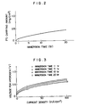
- Fig. 2 is a graph showing a relationship between a platinum carrying amount and an immersion time when a graphite intercalation compound used as an electrode is immersed in a chloroplatinic acid solution according to Example 1 of this invention.
- Fig. 3 is a graph showing a relationship between a current density and a voltage based on hydrogen according to Example 1 of this invention.
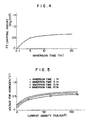
- Fig. 4 is a graph showing a relationship between a platinum carrying amount and an immersion time when a graphite intercalation compound used as an electrode is immersed in a chloroplatinic acid solution according to Example 2 of this invention.
- Fig. 5 is a graph showing a relationship between a current density and a voltage based on hydrogen according to Example 2 of this invention.
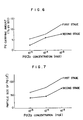
- Fig. 6 is a graph showing a relationship between a palladium carrying amount and a palladium chloride concentration according to Example 3 of this invention.
- Fig. 7 is a graph showing a relationship between a palladium particle size and a palladium chloride concentration according to Example 3 of this invention.
- Fig. 8 is a graph showing cell performance when a fuel electrode according to Example 3 of this invention is used in a hydrazine fuel cell.
- Fig. 9 is a graph showing X-ray diffraction of carbon fiber carrying a catalytic active component according to Example 5 of this invention.
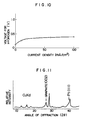
- Fig. 10 ia a graph showing cell performance when a fuel electrode according to Example 5 of this invention is used in a methanol fuel cell.
- Fig. 11 is a graph showing X-ray diffraction of graphite particles carrying platinum obtained in Example 8.
- the fuel cell electrode of this invention has a structure wherein at least one catalytic active component selected from noble metals belonging to the group I, particularly Ib such as Au, Ag, etc. and the group VIII such as Ru, Rh, Pd, Os, Ir, Pt, etc., is carried on surfaces and among lamellar crystalline layers of a porous electroconductive substrate made of graphite having lamellar crystalline layers.
- at least one catalytic active component selected from noble metals belonging to the group I, particularly Ib such as Au, Ag, etc. and the group VIII such as Ru, Rh, Pd, Os, Ir, Pt, etc. is carried on surfaces and among lamellar crystalline layers of a porous electroconductive substrate made of graphite having lamellar crystalline layers.
- the electrode having such a structure can be produced by the following steps. First, a porous electroconductive substrate is made of graphite having lamellar crystalline layers. Then, one or more alkali metals and alkaline earth metals are intercalated among layers of graphite lamellar crystals to produce a donor-type graphite intercalation compound (hereinafter referred to as "donor-type GIC").
- the donor-type GIC is immersed in an organic solvent dissolving at least one salt of metal having a catalytic activity selected from metals belonging to the group Ib of the periodic table such as Au and Ag and group VIII of the periodic table such as Ru, Rh, Pd, Os, Ir, Pt, etc.
- the intercalant that is, the alkali metal or alkaline earth metal in the GIC and the metal having catalytic activity ionized in the organic solvent are subjected to ion exchange so as to carry the metal having catalytic activity among lamellar crystalline layers of graphite. Further, the above-mentioned metal salt having catalytic activity is reduced and carried on surfaces of the porous electroconductive substrate.
- the electrode having such a structure as carrying the catalytic active component by using the ion exchange reaction or reduction reaction and using the graphite intercalation compound as starting material have advantages in that the particle size of catalytic active component is small and the dispersibility of the catalytic active compound is good compared with a known electrode obtained by coating an electrode catalyst on a porous electroconductive substrate using a binder. Therefore, the catalytic active component carried on the substrate can be applied effectively in the cell reaction.
- Methanol fuel cells, hydrazine fuel cells, and phosphoric acid electrolyte fuel cells using the electrode of this invention can have higher cell voltage than fuel cells having electrodes obtained by coating electrode catalysts on porous electroconductive substrates.
- the intercalation compound comprises a lamellar substance and an intercalant and can be divided into a donor-type compound and an acceptor-type compound.
- the graphite intercalation compound is obtained by combining graphite which is a lamellar substance with an intercalant by ionic bonding.
- Graphite has a structure of laminated planes of hexagonal network of carbon atoms and one or more intercalants are intercalated among carbon planes.
- intercalant forming intercalation compounds with graphite there can be used alkali metals, alkaline earth metals, halogens, halides and acids.
- the acceptor-type GIC is stable in the atmosphere.
- the acceptor-type GIC is used as porous electroconductive substrate by effectively using its property of stable in the atmosphere and coating electrode catalysts on the substrate by using a binder.
- the donor-type GIC is unstable in the atmosphere and easily changes its properties by easily reacting with oxygen or moisture in the atmosphere when contacted.
- the present inventors have found that when a donor-type GIC is contacted with an ionized catalyst element in an inert gas or in a liquid which does not substantially react with the donor-type GIC, the catalyst element can be carried on surfaces and among layers of graphite by ion exchange reaction between the GIC and the ionized catalyst element and reduction of the catalyst element by charge transfer. That is, the present inventors have found that the donor-type GIC acts as a reducing agent in the carrying of catalytic active components.
- the acceptor-type intercalation compound does not act as a reducing agent.
- the action as a reducing agent for GICs is specific to the donor-type GIC. Therefore, the donor-type GIC is used as starting material.
- the catalytic active component can directly be carried on graphite without using a binder. Therefore, there arises no problem of generating cracks on the catalyst layer unlike the electrodes of prior art obtained by coating the catalyst using a binder.
- the catalytic active component is carried on the surfaces and among crystalline layers of graphite by the ion exchange reaction and the reduction, the bonding is remarkably strong and there is no problem of peeling.
- the fuel cell electrode of this invention has a structure wherein intercalants in the donor-type GIC is replaced by the catalytic active component by the ion exchange reaction. Therefore, the electrode of this invention has a single-layer structure compared with the double-layer structure of the prior art electrodes.
- the fuel cell electrode of this invention has smaller electrode constituting elements than the prior art electrodes. Therefore, it becomes possible to make the electrode thinner. Further, in this invention, since the graphite which is a lamellar substance forms both the current collecting portion and the catalyst carrying portion, the resulting electrode can have good catalytic activity and low electrical resistance properties at the same time.
- the shape of fuel cell electrode can be made by using graphite. Therefore, it is preferable to form a porous substrate having the desired shape by molding graphite previously.
- the thickness of the porous substrate may be the same or slightly thinner compared with that of prior art catalyst coated electrode. The thickness of about 0.1 to 2 mm is sufficient.
- the porous electroconductive substrate of graphite is preferably obtained by molding using carbon fibers. It is preferable to use carbon fibers having a diameter of 1 ⁇ m ⁇ 0.5 ⁇ m.
- the length of carbon fibers is not critical and may be short fibers of about 2 to 3 mm long or long fibers.
- the carbon fibers are most preferably made by using pitch as a starting material.
- the intercalation compounds obtained by using pitch are easy in intercalating intercalants and removing intercalants.
- the porous electroconductive substrate In order to produce the porous electroconductive substrate from carbon fiber, there can be used carbon fiber non-woven fabrics, carbon fiber woven fabrics, etc.
- the porous electroconductive substrate When non-graphitized carbon fiber is used, the porous electroconductive substrate may be molded after graphitizing the carbon fiber or the porous electronconductive substrate may be molded first by using non-graphitized carbon fiber, followed by graphitization.
- graphitization means graphitization of whole or surface layer of carbon fiber or carbon powder.
- the graphitized substrate is made porous in order to pass a fuel or oxidant through the holes. It is preferable to make the pore size 1 to 50 ⁇ m and the porosity 85 to 95%.
- the catalytic active component there are known various catalytic active components.
- noble metals belonging to the group I, preferably the group Ib, and the group VIII of the periodic table are preferable in this invention.
- noble metals are ruthenium (Ru), rhodium (Rh), palladium (Pd), osmium (Os), iridium (Ir), platinum (Pt), gold (Au), silver (Ag), etc.
- Ru ruthenium
- Rh rhodium
- Pd palladium
- Ir iridium
- platinum platinum
- gold Au
- silver silver
- These metals can be used alone or as a mixture thereof, in the form of a metal or salts thereof such as chlorides, nitrates, and the like.
- the catalytic active component is carried on the substrate preferably in an amount of 0.1 to 2 mg per cm2 of apparent surface area of the electrode.
- the electrode of this invention carrying the catalytic active component among lamellar crystalline layers and on surfaces of graphite can be produced by contacting a donor-type GIC used as a substrate with an ionized catalytic active component, and conducting an ion exchange reaction and a reduction reaction so as to carry the catalytic active component on the substrate.
- the ion exchange reaction and the reduction reaction are preferably carried out in an inert gas or in a solution, since the donor-type GIC is unstable in the atmosphere.
- the shape of porous electroconductive substrate is not limited and can be selected optionally.
- the catalyst element can be carried on the surfaces and among the lamellar crystalline layers of graphite uniformly even if any shapes are taken.
- the fuel cell electrode of this invention it is remarkably effective to conduct water repellent treatment on the surfaces of electrode, particularly the surface at the side of the electrolyte. In such a case, a care should be taken so as not to conduct the water repellent treatment on the surface of catalytic active component.
- the water repellent treatment In order to prevent the catalytic active component surface from the water repellent treatment, it is preferable to conduct the water repellent treatment before the carrying of catalytic active component on the substrate. As a process for attaining such a purpose, it is desirable to immerse the graphite intercalation compound in a liquid dispersing a water repellent substance.
- the water repellent substance polytetrafluoroethylene is preferable.
- the catalytic active component can be carried at least among lamellar crystalline layers of graphite substrate by contacting the ionized catalytic active component with the graphite substrate.
- a water repellent treated fuel cell electrode can be produce by, for example, the following process.
- a porous electroconductive substrate made from carbon fiber woven fabric or carbon fiber non-woven fabric, at least carbon fiber surface having been graphitized, is immersed in a polytetrafluoroethylene solution.
- the resulting porous electroconductive substrate is subjected to intercalation of an alkali metal or alkaline earth metal at the surface portion of graphite of individual carbon fibers to give a donor-type graphite intercalation compound.
- the donor-type graphite intercalation compound is contacted with an ionized catalytic active component to carry the cataytic active component on the surfaces and among lamellar crystalline layers of graphite while conducting an ion exchange reaction and a reduction reaction.
- the donor-type graphite intercalation compound is immersed in a solution obtained by dissolving one or more metal salts having catalytic activity in an organic solvent such as tetrahydrofuran, dimethoxyethylene, etc.
- the donor-type graphite intercalation compound can be produced, for example, as follows.
- a vessel carbon fiber at least surface of which is graphitized and an intercalant such as an alkali metal or alkaline earth metal are placed with mixing together or separately in different positions in the vessel.
- the vessel is sealed in vacuum of 1.33 ⁇ 10 ⁇ 5 Pa (10 ⁇ 3Torr) or less.
- the alkali metal or alkaline earth metal may be a single metal, a mixture of different kinds of metals, or an alloy.
- the vessel is put in an electric furnace for heat treatment.
- the carbon fiber at least surface of which is graphitized and the alkali metal or alkaline earth metal are mixed together and placed in the vessel, it is preferable to heat the whole vessel at the same temperature.
- the carbon fiber and the alkali metal or alkaline earth metal are placed in different positions in the vessel, it is preferable to control the temperature of the carbon fiber placed position and the temperature of the alkali metal or alkaline earth metal placed position separately.
- a donor-type graphite intercalation compound having the desired stage number can be produced by making the temperature difference between the carbon fiber placed position and the alkali metal or alkaline earth metal placed position 50 to 300°C. Either the temperature of the carbon fiber placed position or the temperature of the alkali metal or alkaline earth metal placed position can be made higher.
- the heating temperature at high temperature portion is preferably 200 to 700°C.
- the stage number is a parameter showing an anisotropic orientation type structure of an intercalant at the time of forming a donor-type intercalation compound by inserting the intercalant such as an alkali metal or alkaline earth metal between hexagonal layer planes of graphite crystals.
- the first stage means that the intercalant is coordinated or inserted between the hexagonal layer planes at intervals of one plane
- the third stage means that the intercalant is coordinated or inserted between the hexagonal layer planes at intervals of three planes.
- the intercalant When the whole vessel is heated at the same temperature, it is preferable to add the intercalant in an amount slightly larger than the stoichiometric amount of the donor-type graphite intercalation compound having the desired stage number, since the mixing ratio of the intercalant and the carbon fiber influences properties of the product.
- the donor-type graphite intercalant compound is stable in an inert gas, but is broken in the air due to the reaction between the water molecule and the intercalant. Therefore, the water content in the organic solvent into which the donor-type graphite intercalation compound is to be immersed should be adjusted so as not to bring about substantially the reaction between the intercalant in the graphite intercalation compound and the water. More concretely, when the water content in the organic solvent is 200 ppm or less, the donor-type graphite intercalation compound is substantially stable.
- the organic solvent which can be purified so as to contain water 200 ppm or less and can dissolve noble metal salts are aromatic organic solvents, particularly preferably tetrahydrofuran, benzene, quinoline, and the like.
- Examples of the noble metal salt to be dissolved in the organic solvent are salts of Ir, Os, Rh, Pd, Pt, and Ru belonging to the group VIII and Ag and Au belonging to the group Ib of the periodic table. Among them, those in the form of noble metal salt hydrates are preferable.
- the noble metal salt hydrates can be dissolved in an aromatic organic solvent larger in amounts than the noble metal salts containing no water of crystallization and are suitable for realizing very fine dispersion of noble metal elements. In such a case, when the water content in the noble metal salts is large, it is preferable to conduct dehydration of the aromatic organic solvent so as to make the water content 200 ppm or less after dissolving the noble metal salt therein.
- the donor-type graphite intercalation compound is reacted with the noble metal dissolved in the aromatic organic solvent.
- the solution contains noble metal ions, anions, water molecules, and aromatic organic compound (solvent) molecules.
- the noble metal ions and water molecules interact with the donor-type graphite intercalation compound.
- the water molecules interact with the intercalant in the donor-type graphite intercalation compound so as to take out the intercalant among crystalline layers of graphite.
- the noble metal ions interact with the intercalant so as to penetrate into the crystalline layers of graphite and at the same time they are attracted to the surfaces of layers of graphite to form a colony of noble metal element thereon. These changes can be judged qualitatively from the disappearance of color specific to the noble metal ions.
- the end point is set at a point wherein the color specific to noble metal salt does not disappear, which results in making it possible to produce noble metal particles having a particle size of 2nm or less.
- a donor-type graphite intercalation compound having a higher stage number so as to disperse the sites, on which noble metal particles are adsorbed, at intervals.
- the intercalant is coordinated in the hexagonal layers of graphite at intervals of many layers in the case of a higher stage donor-type graphite intercalation compound
- the noble metal ions which interact with the intercalant and penetrate into the layers also take the positions at intervals of many layers of hexagonal layers so as to enhance the dispersion state of the noble metal particles.
- Another method for enhancing the degree of dispersion of noble metal particles is to partially destroy the donor-type graphite intercalation compound by using water molecules so as to lower the concentration of the intercalant and to make the donor-type graphite intercalation compound have a higher stage number, thus limiting the sites on which the noble metal particles are adsorbed. That is, using an aromatic organic compound solution dissolving a noble metal salt hydrate, the donor-type graphite intercalation compound is reacted with the water of crystallization of the noble metal salt hydrate to remove the intercalant from the layers of graphite, followed by the reaction of the remained donor-type graphite intercalant compound with the noble metal ions.
- the methanol fuel cell or phosphoric acid electrolyte-type fuel cell comprises a pair of electrodes placed oppositely, an electrolyte disposed between both the electrodes so as to contact with the electrodes, a fuel chamber placing neighboring to a fuel electrode of the pair of electrodes, an oxidant chamber placed neighboring to an oxidant electrode of the pair of electrodes, a fuel supplying means to the fuel chamber, and an oxidant supplying means to the oxidant chamber.
- an acidic electrolyte solution such as dilute sulfuric acid is usually used as electrolyte.
- an oxygen-containing gas such as air is usually used.
- a hydrogen-containing gas is usually used as a fuel, and an oxygen-containing gas such as air is usually used as oxidant.
- the fuel cell electrode of this invention can be used as the fuel electrode and/or oxidant electrode in the fuel cells having the above-mentioned structures.
- the electrode can be placed in a cell in the state of reinforced with other reinforcing material. But in such a case, it is preferable to use the reinforcing material in porous structure such as net or lattice state so as not to damage the flow of fuel or oxidant.
- Fig. 1 shows a principle of unit cell of fuel cell.
- numeral 1 denotes a fuel electrode, 2 an oxidant electrode, 3 an electrolyte disposed between the fuel electrode 1 and the oxidant electrode 2.
- a fuel chamber 5 to which a fuel 5 is sent is formed neighboring to the fuel electrode 1
- an oxidant chamber 7 to which an oxidant 6 is sent is formed neighboring to the oxidant electrode 2.
- a supplying means for fuel 4 and a supplying means for oxidant 6 are omitted.
- methanol is used in the methanol fuel cell, and hydrogen or a hdyrogen-containing gas is used in the phosphoric acid fuel cell.
- oxygen or an oxygen-containing gas such as air is used as the oxidant 6.
- nitrogen gas is generated as generated gas.
- Numerals 10 and 11 show current collecting terminals.
- At least one of the fuel electrode 1 and the oxidant electrode 2 uses the electrode of this invention obtained by using as a starting material the donor-type graphite intercalation compound and carrying the catalytic active component thereon by the ion exchange reaction.
- the fuel electrode 1 or the oxidant electrode 2 is composed by including the passage of fuel 4, the removing passage for generated gas 8 at the fuel electrode, and the terminals, but these passages and terminals can be produced by using an electroconductive material generally used in place of the special material obtained by using a graphite intercalation compound as a starting material.
- a first stage graphite intercalation compound having a golden color was synthesized by sealing carbon fiber non-woven fabric obtained by using pitch as a raw material and metallic potassium in a glass tube in vacuum at a degree of vacuum of 10 ⁇ 1 Pa and heating the whole glass tube at 250°C for 8 hours.
- the resulting graphite intercalation compound was immersed in a tetrahydrofuran (C4H8O) solution dissolving chloroplatinic acid (H2PtCl6 ⁇ 6H2O) in a concentration of 1.8 x 10 ⁇ 3 mole with water content of 35 ppm.
- the immersion time was changed 1 hour, 5 hours, 10 hours and 20 hours, and the platinum carrying amount was measured by the light absorption method. The results are shown in Fig. 2.
- the thus produced electrodes carrying platinum among crystalline layers of graphite were used as a fuel electrode in methanol fuel cells.
- a voltage against hydrogen was measured and shown in Fig. 3 in relation to a current density. As is clear from Fig. 3, the lower the voltage against hydrogen, the higher the electrode performance.
- the electrode of this invention is remarkably better in performance than the prior art one.
- Carbon fiber woven fabric obtained by using pitch as a raw material and metallic potassium were placed in a glass tube and sealed in vacuum at a degree of vacuum of 10 ⁇ 1 Pa.
- the weight ratio of the carbon fiber woven fabric to the metallic potassium was 5:1.
- the glass tube was heat treated at 270°C for 10 hours to give a dark blue second stage graphite-potassium intercalation compound.
- the resulting second stage graphite-potassium intercalation compound was immersed in a tetrahydrofuran (C4H8O) solution dissolving chloroplatinic acid (H2PtCl6 ⁇ 6H2O) in a concentration of 1.2 x 10 ⁇ 4 mole with water content of 38 ppm for 1, 5, 10 or 20 hours to carry the platinum on the carbon fiber.
- C4H8O tetrahydrofuran
- chloroplatinic acid H2PtCl6 ⁇ 6H2O
- the thus produced electrodes were installed in methanol fuel cells as a fuel electrode and the electrode performance was measured and shown in Fig. 5.
- Carbon fiber non-woven fabric obtained by using pitch as a raw material and metallic potassium were placed on both end portions of a glass tube and sealed in vacuum at a degree of vacuum of 10 ⁇ 3 Pa.
- the glass tube was heat treated at 270°C to give both first stage and second stage graphite-potassium intercalation compounds.
- palladium chloride (PdCl2 ⁇ 2H2O) was dissolved to give solutions of concentrations of 1.0 x 10 ⁇ 3 mole, 1.0 x 10 ⁇ 4 mole, and 1.0 x 10 ⁇ 5 mole, respectively.
- the graphite intercalation compounds were immersed for 48 hours, dried in vacuum, washed with water and distilled water, and dried in vacuum to give electrodes.
- the thus produced electrode was installed in a hydrazine fuel cell as a fuel electrode and the electrode performance was measured and shown in Fig. 8.
- Carbon fiber woven fabric obtained by using pitch as a raw material and metallic cesium were placed separately on both end portions of a glass tube and sealed in vacuum at a degree of vacuum of 10 ⁇ 2 Pa.
- the carbon fiber woven fabric portion of the glass tube was heated at 250°C and the metallic cesium portion of the glass tube was heated at 194°C for about 20 hours to produce a dark blue second stage graphite-cesium intercalation compound.
- dehydration purified dimethoxyethene (DME) chloroplatinic acid
- RuCl2 ⁇ xH2O ruthenium chloride
- the concentrations of chloroplatinic acid and ruthenium chloride were 2.1 x 10 ⁇ 2 mole, respectively.
- the above-mentioned graphite-cesium intercalation compound was immersed for 3 hours to carry platinum and ruthenium on the carbon fiber.
- X-ray diffration of the resulting carbon fiber was shown in Fig. 9.
- the platinum carried on the carbon fiber woven fabric was 0.7 mg/cm2.
- the thus produced electrode was installed in a methanol fuel cell as a fuel electrode and the electrode performance was measured and shown in Fig. 10.
- the first stage graphite intercalation compound means a graphite intercalation compound wherein an intercalant (potassium in this Example) is inserted between every crystalline layer of graphite.
- the resulting graphite intercalation compound-formed carbon fiber non-woven fabric was immersed in a solution of tetrahydrofuran (C4H8O) dissolving chloroplatinic acid (H2PtCl6 ⁇ 6H2O) to conduct ion exchange reaction between the graphite-potassium intercalation compound and the platinum cations.
- C4H8O tetrahydrofuran
- H2PtCl6 ⁇ 6H2O chloroplatinic acid
- the thus treated carbon fiber non-woven fabric was confirmed by X-ray diffraction to carry platinum catalyst on the surfaces and among crystalline layers of graphite formed on surface portions of individual carbon fibers. Further, it was also confirmed that the polytetrafluoroethylene was separately distributed among carbon fibers.
- the carbon fiber non-woven fabric thus treated could maintain the water repellent properties even after immersed in water for 1000 hours.
- the carbon fiber non-woven fabric After impregnating carbon fiber non-woven fabric having a thickness of 1.2 mm with polytetrafluoroethylene in an amount of 9 mg/cm2, the carbon fiber non-woven fabric thus treated and metallic rubidium were placed separately on both end portions of a glass tube and sealed in vacuum at a degree of vacuum of 10 ⁇ 2 Pa.
- the glass tube as placed in an electric furnace which could control the heating temperature at two points.
- the carbon fiber non-woven fabric portion was heat treated at 400°C and the metallic rubidium portion was heat treated at 208°C for 4 hours to give a dark blue second stage graphite-rubidium intercalation compound.
- the second stage graphite intercalation compound means a graphite intercalation compound wherein an intercalant (rubidum in this Example) is inserted between crystalline layers of graphite at intervals of two layers.
- the resulting graphite intercalation compound-formed carbon fiber non-woven fabric was immersed in a solution of tetrahydrofuran (C4H8O) dissolving potassium chloroplatinate (K2PtCl6) to conduct ion exchange reaction between the graphite intercalation compound and the platinum cations.
- C4H8O tetrahydrofuran
- K2PtCl6 potassium chloroplatinate
- the carbon fiber non-woven fabric thus treated could maintain the water repellent properties even after immersed in water for 1000 hours.
- the resulting graphite intercalation compound-formed carbon fiber woven fabric was immersed in a solution of tetrahydrofuran dissolving chloroauric acid (H AuCl4) and ruthenium chloride (RuCl3 ⁇ xH2O).
- the water content of the tetrahydrofuran solution was 21 ppm.
- the carbon fiber woven fabric thus treated could maintain the water repellent properties even after immersed in water for 1000 hours.
- chloroplatinic acid H2PtCl6 ⁇ 6H2O
- H2PtCl6 ⁇ 6H2O chloroplatinic acid
- the tetrahydrofuran solution was added dropwise to the glass bottle until the orange color specific to the chloroplatinic acid did not disappear, followed by standing still for 24 hours. Then, the resulting graphite was filtered, washed with distilled water until the potassium chloride deposited on the surface disappeared, followed by drying in vacuum.
- X-ray diffraction of the resulting material is shown in Fig. 11.
- platinum element is present in the internal portions and on the surface portion of the graphite material.
- TEM image revealed that the particle size of platinum particles dispersed in the graphite material was about 1 nm.
- the amount of platinum dispersed in the graphite material was 1.5% by weight.
- a pyrex glass tube In a pyrex glass tube, a mixture of 1 g of graphite powder and 0.8 g of metallic potassium were placed and sealed in vacuum at a degree of vacuum of 1.33 ⁇ 10 ⁇ 6 Pa (10 ⁇ 4 Torr). The pyrex glass tube was placed in a constant temperature bath at 250°C for 24 hours for heat treatment to produce a golden first stage graphite-potassium intercalation compound kC8. The resulting first stage graphite-potassium intercalation compound was transferred to a glass bottle under an argon atmosphere.
- a solution prepared by dissolving sodium-palladium chloride (PdCl2 ⁇ 2NaCl ⁇ 3H2O) in a concentration of 1.4 x 10 ⁇ 3 mole in tetrahydrofuran (C4H8O) previously prepared by dehydration purification so as to make the water content 200 ppm was added dropwise to the glass bottle until the darkish red color specific to the sodium-palladium chloride did not disappear, followed by standing still for 24 hours. Then, the resulting graphite was filtered, washed with water, and dried by using a vacuum drier.
- X-ray diffraction pattern and TEM image revealed that palladium particles with a particle size of several tens angsroms were uniformly dispersed on the surfaces of the graphite.
- a graphite plate grown up in the air was placed at one end and rubidium (Rb) was placed at another end.
- the class tube was sealed in vacuum at a degree of vacuum of 1.33 ⁇ 10 ⁇ 6 Pa (10 ⁇ 4 Torr).
- the glass tube was heated so as to heat the graphite portion at 400°C and the rubidium portion at 210°C for 24 hours to produce a second stage graphite-rubidium intercalation compound RbC24.
- the resulting second stage graphite-rubidium intercalation compound was transferred to a glass bottle under an argon atmosphere.
- X-ray diffraction pattern and TEM image revealed that ruthenium particles with a particle size of 1.5 nm were dispersed uniformly on the surface and interior of the graphite plate.
- a graphite powder was placed in the central portion of a pyrex glass tube and rubidium (Rb) and potassium (K) were placed separately at end portions of the glass tube.
- the glass tube was sealed in vacuum at a degree of vacuum or 1.33 ⁇ 10 ⁇ 6 Pa (10 ⁇ 4 Torr).
- the rubidium portion was heated at 220°C, the graphite portion at 210°C and the potassium portion at 240°C for 48 hours to produce a graphite-alkali metal intercalation compound K x Rb 1-x C8.
- the resulting graphite intercalation compound was transferred to a glass bottle under an argon atmosphere.
- X-ray diffraction pattern and TEM image revealed that platinum particles with a maximum particle size of 2 nm were dispersed on the surface and interior of the graphite material.
- the fuel cell electrode of this invention directly carrys the catalytic active component between the graphite crystalline layers and on the surfaces of graphite intercalation compound. Therefore, it is not necessary to use a binder unlike the prior art electrodes. Further, it is not necessary to use a carrier. In addition, since the catalytic active component is carried on the graphite intercalation compound in place of the intercalant, the dispersibility of the catalytic active component is good.
- the fuel cells containing such electrodes therein show higher cell performance than those containing prior art catalyst coating type electrodes therein.
Landscapes
- Chemical & Material Sciences (AREA)
- Chemical Kinetics & Catalysis (AREA)
- Electrochemistry (AREA)
- General Chemical & Material Sciences (AREA)
- Inert Electrodes (AREA)
Claims (10)
- Électrode de pile à combustible, caractérisée en ce qu'elle comprend au moins un composant catalytique actif choisi parmi les métaux précieux appartenant au groupe I et au groupe VIII du tableau périodique, placés sur des surfaces et entre des couches cristallines lamellaires d'un substrat électroconducteur poreux réalisé en un composé d'insertion en graphite du type donneur.
- Électrode de pile à combustible selon la revendication 1, caractérisée en ce que ledit composé est obtenu à partir de graphite et d'au moins un élément choisi parmi des métaux alcalins et des métaux alcalino-terreux.
- Électrode de pile à combustible selon la revendication 2, caractérisée en ce que le graphite est une fibre de carbone possédant une structure à couches graphitées.
- Électrode de pile à combustible selon la revendication 1, caractérisée ce que le composant catalytique actif est disposé en une quantité de 0,1 à 2 mg par cm² de surface apparente de l'électrode.
- Électrode de pile à combustible selon la revendication 1, caractérisée en ce que toutes les surfaces hormis celles prévues pour le composant catalytique actif sont recouvertes par une substance hydrophobe.
- Procédé pour fabriquer une électrode de pile à combustible, caractérisé par la mise en contact d'un substrat électroconducteur poreux formé d'un composé d'insertion en graphite du type donneur, avec au moins un composant catalytique actif choisi parmi des métaux précieux appartenant au groupe I et au groupe VIII du tableau périodique de manière à placer le composant catalytique actif sur des surfaces et entre des couches cristallines lamellaires du graphite moyennant une réaction d'échange d'ions ou une réduction du composant catalytique actif.
- Procédé selon la revendication 6, caractérisé en ce qu'on recouvre le substrat électroconducteur poreux par une substance hydrophobe avant d'y déposer le composant catalytique actif.
- Procédé selon la revendication 6 ou 7, caractérisé en ce qu'on forme le composé d'insertion en graphite du type donneur en intercalant dans un substrat poreux formé d'une fibre de carbone au moins un élément choisi parmi des métaux alcalins et des métaux alcalino-terreux.
- Procédé selon la revendication 6 ou 7, caractérisé en ce que la réaction d'échange d'ions est mise en oeuvre dans une atmosphère de gaz inerte ou par immersion du composé d'insertion en graphite dans une solution contenant un sel du composant catalytique actif.
- Pile à combustible comportant un couple d'électrodes disposées en vis-à-vis, un électrolyte disposé entre ces deux électrodes en étant en contact avec elles, une chambre à combustible placée au voisinage d'une électrode à combustible du couple d'électrodes, une chambre contenant un agent oxydant et placée au voisinage d'une électrode délivrant l'agent oxydant, qui fait partie du couple d'électrodes, des moyens d'amenée du combustible à la chambre logeant le combustible, et des moyens d'amenée de l'agent oxydant à la chambre contenant l'agent oxydant, caractérisée en ce qu'au moins l'une des électrodes comprend au moins un composant catalytique actif choisi parmi des métaux précieux appartenant au groupe I et au groupe VIII du tableau périodique, disposés sur des surfaces et entre des couches cristallines lamellaires d'un substrat électroconducteur poreux réalisé en un composé d'insertion en graphite du type donneur.
Applications Claiming Priority (4)
| Application Number | Priority Date | Filing Date | Title |
|---|---|---|---|
| JP63376/84 | 1984-04-02 | ||
| JP59063376A JPS60208054A (ja) | 1984-04-02 | 1984-04-02 | 燃料電池用電極と製造法並びにその電極を用いた燃料電池 |
| JP66558/84 | 1984-04-03 | ||
| JP59066558A JPS60211774A (ja) | 1984-04-03 | 1984-04-03 | 撥水性触媒電極とその製造方法 |
Publications (3)
| Publication Number | Publication Date |
|---|---|
| EP0157385A2 EP0157385A2 (fr) | 1985-10-09 |
| EP0157385A3 EP0157385A3 (en) | 1987-09-30 |
| EP0157385B1 true EP0157385B1 (fr) | 1991-06-12 |
Family
ID=26404495
Family Applications (1)
| Application Number | Title | Priority Date | Filing Date |
|---|---|---|---|
| EP85103809A Expired - Lifetime EP0157385B1 (fr) | 1984-04-02 | 1985-03-29 | Electrode de pile à combustible, procédé de fabrication et pile à combustible utilisant une telle électrode |
Country Status (4)
| Country | Link |
|---|---|
| US (1) | US4614692A (fr) |
| EP (1) | EP0157385B1 (fr) |
| CA (1) | CA1244873A (fr) |
| DE (1) | DE3583170D1 (fr) |
Families Citing this family (17)
| Publication number | Priority date | Publication date | Assignee | Title |
|---|---|---|---|---|
| JPH0282455A (ja) * | 1988-09-16 | 1990-03-23 | Tanaka Kikinzoku Kogyo Kk | ガス拡散電極構成用微粉体・多孔質体及びその撥水化処理方法 |
| US5041195A (en) * | 1988-11-17 | 1991-08-20 | Physical Sciences Inc. | Gold electrocatalyst, methods for preparing it, electrodes prepared therefrom and methods of using them |
| US5133842A (en) * | 1988-11-17 | 1992-07-28 | Physical Sciences, Inc. | Electrochemical cell having electrode comprising gold containing electrocatalyst |
| US5132193A (en) * | 1990-08-08 | 1992-07-21 | Physical Sciences, Inc. | Generation of electricity with fuel cell using alcohol fuel |
| US5543021A (en) * | 1994-09-01 | 1996-08-06 | Le Carbone Lorraine | Negative electrode based on pre-lithiated carbonaceous material for a rechargeable electrochemical lithium generator |
| FR2782462B1 (fr) * | 1998-08-21 | 2000-09-29 | Atochem Elf Sa | Procede pour ameliorer l'adherence de particules metalliques sur un substrat carbone |
| DE60142897D1 (de) | 2000-06-02 | 2010-10-07 | Stanford Res Inst Int | Polymermembranzusammensetzung |
| US20020022170A1 (en) * | 2000-08-18 | 2002-02-21 | Franklin Jerrold E. | Integrated and modular BSP/MEA/manifold plates for fuel cells |
| US6582846B2 (en) * | 2001-05-31 | 2003-06-24 | Graftech, Inc. | Method for preparing fuel cell component substrate of flexible graphite material having improved catalytic properties |
| AU2002312178A1 (en) | 2001-06-01 | 2002-12-16 | Polyfuel, Inc | Fuel cell assembly for portable electronic device and interface, control, and regulator circuit for fuel cell powered electronic device |
| US7316855B2 (en) | 2001-06-01 | 2008-01-08 | Polyfuel, Inc. | Fuel cell assembly for portable electronic device and interface, control, and regulator circuit for fuel cell powered electronic device |
| AU2002358277A1 (en) * | 2001-12-27 | 2003-07-24 | Aerogel Composite, Llc | Aerogel and metallic compositions |
| US20040141908A1 (en) * | 2002-12-20 | 2004-07-22 | Hara Hiroaki S. | Aerogel and metallic composites |
| US7670707B2 (en) * | 2003-07-30 | 2010-03-02 | Altergy Systems, Inc. | Electrical contacts for fuel cells |
| WO2006121981A2 (fr) | 2005-05-06 | 2006-11-16 | Ohio University | Electrocatalyseurs, et additifs d'oxydation de carburants solides |
| GB201802316D0 (en) | 2018-02-13 | 2018-03-28 | Ucl Business Plc | Nanomaterial preparation method |
| JP7032973B2 (ja) * | 2018-03-29 | 2022-03-09 | 太陽誘電株式会社 | 全固体電池およびその製造方法 |
Family Cites Families (8)
| Publication number | Priority date | Publication date | Assignee | Title |
|---|---|---|---|---|
| DE1771801A1 (de) * | 1968-07-12 | 1972-02-03 | Dow Chemical Co | Hyperleitfaehige Graphitstrukturgefuege |
| US4293396A (en) * | 1979-09-27 | 1981-10-06 | Prototech Company | Thin carbon-cloth-based electrocatalytic gas diffusion electrodes, and electrochemical cells comprising the same |
| US4369104A (en) * | 1979-10-22 | 1983-01-18 | Hitco | Continuous filament graphite composite electrodes |
| JPS5768142A (en) * | 1980-10-14 | 1982-04-26 | Hitachi Ltd | Electrode catalyst for fuel cell and its production |
| JPS57124864A (en) * | 1981-01-28 | 1982-08-03 | Sanyo Electric Co Ltd | Gas diffusion electrode of fuel cell |
| US4407906A (en) * | 1981-11-03 | 1983-10-04 | Paul Stonehart | Fuel cell with Pt/Pd electrocatalyst electrode |
| US4430391A (en) * | 1982-07-19 | 1984-02-07 | Energy Conversion Devices, Inc. | Fuel cell cathode |
| JPS60125249A (ja) * | 1983-12-08 | 1985-07-04 | Hitachi Ltd | 触媒金属微細分散黒鉛材料及びその製造方法 |
-
1985
- 1985-03-29 CA CA000477977A patent/CA1244873A/fr not_active Expired
- 1985-03-29 EP EP85103809A patent/EP0157385B1/fr not_active Expired - Lifetime
- 1985-03-29 DE DE8585103809T patent/DE3583170D1/de not_active Expired - Lifetime
- 1985-04-02 US US06/719,080 patent/US4614692A/en not_active Expired - Lifetime
Also Published As
| Publication number | Publication date |
|---|---|
| EP0157385A2 (fr) | 1985-10-09 |
| US4614692A (en) | 1986-09-30 |
| CA1244873A (fr) | 1988-11-15 |
| DE3583170D1 (de) | 1991-07-18 |
| EP0157385A3 (en) | 1987-09-30 |
Similar Documents
| Publication | Publication Date | Title |
|---|---|---|
| EP0157385B1 (fr) | Electrode de pile à combustible, procédé de fabrication et pile à combustible utilisant une telle électrode | |
| US5133842A (en) | Electrochemical cell having electrode comprising gold containing electrocatalyst | |
| US5084144A (en) | High utilization supported catalytic metal-containing gas-diffusion electrode, process for making it, and cells utilizing it | |
| EP0920065B1 (fr) | Electrode composite d'électrolyte polymère-catalyseur, électrode pour piles à combustible, et procédé de fabrication de ces électrodes | |
| US6297185B1 (en) | Catalyst | |
| KR101363797B1 (ko) | 연료전지용 전극재료의 제조방법, 연료전지용 전극재료 및 이 연료전지 전극재료를 이용한 연료전지 | |
| CA2003299A1 (fr) | Electrocatalysuer, sa preparation, electrodes derivees de l'electrocatalysuer et leur mode d'emploi | |
| US8304365B2 (en) | Stabilized platinum catalyst | |
| Savadogo et al. | Five percent platinum‐tungsten oxide‐based electrocatalysts for phosphoric acid fuel cell cathodes | |
| JPS5916495B2 (ja) | 担体に担持された貴金属−耐火金属合金触媒を製造する方法 | |
| WO2008070482A2 (fr) | Catalyseurs supportés par nanofil pour des électrodes de pile à combustible | |
| JPS6224908B2 (fr) | ||
| CA2570992A1 (fr) | Support catalyseur pour une pile a combustible electrochimique | |
| KR20100107012A (ko) | Pem 연료 전지를 위한 보호 및 침전 층 | |
| US4513094A (en) | Single-batch process to prepare noble metal vanadium alloy catalyst on a carbon based support | |
| EP0444138B1 (fr) | Electrocatalyseur, ses procedes de preparation, electrodes preparees selon lesdits procedes et leurs modes d'utilisation | |
| US20060287194A1 (en) | Electrode for solid polymer type fuel cell and manufacturing method therefor | |
| JPH07246336A (ja) | 燃料電池用アノード電極触媒及びその製造方法 | |
| JPS6140459B2 (fr) | ||
| AU672276B2 (en) | Air- or oxygen diffusion electrode | |
| Mosdale et al. | New electrodes for hydrogen/oxygen solid polymer electrolyte fuel cell | |
| JPH10102273A (ja) | 水電解セル | |
| JPH0552029B2 (fr) | ||
| JP4934240B2 (ja) | 燃料電池用電極の製造方法 | |
| JPS60211774A (ja) | 撥水性触媒電極とその製造方法 |
Legal Events
| Date | Code | Title | Description |
|---|---|---|---|
| PUAI | Public reference made under article 153(3) epc to a published international application that has entered the european phase |
Free format text: ORIGINAL CODE: 0009012 |
|
| AK | Designated contracting states |
Designated state(s): CH DE FR GB LI NL |
|
| PUAL | Search report despatched |
Free format text: ORIGINAL CODE: 0009013 |
|
| AK | Designated contracting states |
Kind code of ref document: A3 Designated state(s): CH DE FR GB LI NL |
|
| 17P | Request for examination filed |
Effective date: 19880325 |
|
| 17Q | First examination report despatched |
Effective date: 19900126 |
|
| GRAA | (expected) grant |
Free format text: ORIGINAL CODE: 0009210 |
|
| AK | Designated contracting states |
Kind code of ref document: B1 Designated state(s): CH DE FR GB LI NL |
|
| PG25 | Lapsed in a contracting state [announced via postgrant information from national office to epo] |
Ref country code: LI Effective date: 19910612 Ref country code: CH Effective date: 19910612 |
|
| REF | Corresponds to: |
Ref document number: 3583170 Country of ref document: DE Date of ref document: 19910718 |
|
| ET | Fr: translation filed | ||
| REG | Reference to a national code |
Ref country code: CH Ref legal event code: PL |
|
| PLBE | No opposition filed within time limit |
Free format text: ORIGINAL CODE: 0009261 |
|
| STAA | Information on the status of an ep patent application or granted ep patent |
Free format text: STATUS: NO OPPOSITION FILED WITHIN TIME LIMIT |
|
| 26N | No opposition filed | ||
| PGFP | Annual fee paid to national office [announced via postgrant information from national office to epo] |
Ref country code: FR Payment date: 19971217 Year of fee payment: 14 |
|
| PGFP | Annual fee paid to national office [announced via postgrant information from national office to epo] |
Ref country code: GB Payment date: 19971229 Year of fee payment: 14 |
|
| PGFP | Annual fee paid to national office [announced via postgrant information from national office to epo] |
Ref country code: NL Payment date: 19971231 Year of fee payment: 14 |
|
| PGFP | Annual fee paid to national office [announced via postgrant information from national office to epo] |
Ref country code: DE Payment date: 19980331 Year of fee payment: 14 |
|
| PG25 | Lapsed in a contracting state [announced via postgrant information from national office to epo] |
Ref country code: GB Free format text: LAPSE BECAUSE OF NON-PAYMENT OF DUE FEES Effective date: 19990329 |
|
| PG25 | Lapsed in a contracting state [announced via postgrant information from national office to epo] |
Ref country code: NL Free format text: LAPSE BECAUSE OF NON-PAYMENT OF DUE FEES Effective date: 19991001 |
|
| GBPC | Gb: european patent ceased through non-payment of renewal fee |
Effective date: 19990329 |
|
| PG25 | Lapsed in a contracting state [announced via postgrant information from national office to epo] |
Ref country code: FR Free format text: LAPSE BECAUSE OF NON-PAYMENT OF DUE FEES Effective date: 19991130 |
|
| NLV4 | Nl: lapsed or anulled due to non-payment of the annual fee |
Effective date: 19991001 |
|
| REG | Reference to a national code |
Ref country code: FR Ref legal event code: ST |
|
| PG25 | Lapsed in a contracting state [announced via postgrant information from national office to epo] |
Ref country code: DE Free format text: LAPSE BECAUSE OF NON-PAYMENT OF DUE FEES Effective date: 20000101 |