EP0157177B1 - Positionsmesseinrichtung - Google Patents
Positionsmesseinrichtung Download PDFInfo
- Publication number
- EP0157177B1 EP0157177B1 EP85102216A EP85102216A EP0157177B1 EP 0157177 B1 EP0157177 B1 EP 0157177B1 EP 85102216 A EP85102216 A EP 85102216A EP 85102216 A EP85102216 A EP 85102216A EP 0157177 B1 EP0157177 B1 EP 0157177B1
- Authority
- EP
- European Patent Office
- Prior art keywords
- scanning
- areas
- scale
- sub
- analog signal
- Prior art date
- Legal status (The legal status is an assumption and is not a legal conclusion. Google has not performed a legal analysis and makes no representation as to the accuracy of the status listed.)
- Expired - Lifetime
Links
- 230000000737 periodic effect Effects 0.000 claims abstract description 47
- 230000015572 biosynthetic process Effects 0.000 claims abstract description 8
- 238000005259 measurement Methods 0.000 claims description 18
- 238000011156 evaluation Methods 0.000 claims description 14
- 230000010363 phase shift Effects 0.000 claims description 3
- 238000006073 displacement reaction Methods 0.000 claims 3
- 230000004907 flux Effects 0.000 description 4
- 238000005070 sampling Methods 0.000 description 3
- 238000012545 processing Methods 0.000 description 2
- 239000012790 adhesive layer Substances 0.000 description 1
- 238000011109 contamination Methods 0.000 description 1
- 230000008878 coupling Effects 0.000 description 1
- 238000010168 coupling process Methods 0.000 description 1
- 238000005859 coupling reaction Methods 0.000 description 1
- 238000011161 development Methods 0.000 description 1
- 230000018109 developmental process Effects 0.000 description 1
- 238000010586 diagram Methods 0.000 description 1
- 238000000605 extraction Methods 0.000 description 1
- 238000001914 filtration Methods 0.000 description 1
- 238000005286 illumination Methods 0.000 description 1
- 230000001939 inductive effect Effects 0.000 description 1
- 238000000691 measurement method Methods 0.000 description 1
- 238000000034 method Methods 0.000 description 1
- 230000035515 penetration Effects 0.000 description 1
- 230000035699 permeability Effects 0.000 description 1
- 238000007789 sealing Methods 0.000 description 1
Images


Classifications
-
- G—PHYSICS
- G01—MEASURING; TESTING
- G01D—MEASURING NOT SPECIALLY ADAPTED FOR A SPECIFIC VARIABLE; ARRANGEMENTS FOR MEASURING TWO OR MORE VARIABLES NOT COVERED IN A SINGLE OTHER SUBCLASS; TARIFF METERING APPARATUS; MEASURING OR TESTING NOT OTHERWISE PROVIDED FOR
- G01D5/00—Mechanical means for transferring the output of a sensing member; Means for converting the output of a sensing member to another variable where the form or nature of the sensing member does not constrain the means for converting; Transducers not specially adapted for a specific variable
- G01D5/26—Mechanical means for transferring the output of a sensing member; Means for converting the output of a sensing member to another variable where the form or nature of the sensing member does not constrain the means for converting; Transducers not specially adapted for a specific variable characterised by optical transfer means, i.e. using infrared, visible, or ultraviolet light
- G01D5/32—Mechanical means for transferring the output of a sensing member; Means for converting the output of a sensing member to another variable where the form or nature of the sensing member does not constrain the means for converting; Transducers not specially adapted for a specific variable characterised by optical transfer means, i.e. using infrared, visible, or ultraviolet light with attenuation or whole or partial obturation of beams of light
- G01D5/34—Mechanical means for transferring the output of a sensing member; Means for converting the output of a sensing member to another variable where the form or nature of the sensing member does not constrain the means for converting; Transducers not specially adapted for a specific variable characterised by optical transfer means, i.e. using infrared, visible, or ultraviolet light with attenuation or whole or partial obturation of beams of light the beams of light being detected by photocells
- G01D5/36—Forming the light into pulses
-
- G—PHYSICS
- G01—MEASURING; TESTING
- G01D—MEASURING NOT SPECIALLY ADAPTED FOR A SPECIFIC VARIABLE; ARRANGEMENTS FOR MEASURING TWO OR MORE VARIABLES NOT COVERED IN A SINGLE OTHER SUBCLASS; TARIFF METERING APPARATUS; MEASURING OR TESTING NOT OTHERWISE PROVIDED FOR
- G01D5/00—Mechanical means for transferring the output of a sensing member; Means for converting the output of a sensing member to another variable where the form or nature of the sensing member does not constrain the means for converting; Transducers not specially adapted for a specific variable
- G01D5/12—Mechanical means for transferring the output of a sensing member; Means for converting the output of a sensing member to another variable where the form or nature of the sensing member does not constrain the means for converting; Transducers not specially adapted for a specific variable using electric or magnetic means
- G01D5/244—Mechanical means for transferring the output of a sensing member; Means for converting the output of a sensing member to another variable where the form or nature of the sensing member does not constrain the means for converting; Transducers not specially adapted for a specific variable using electric or magnetic means influencing characteristics of pulses or pulse trains; generating pulses or pulse trains
- G01D5/245—Mechanical means for transferring the output of a sensing member; Means for converting the output of a sensing member to another variable where the form or nature of the sensing member does not constrain the means for converting; Transducers not specially adapted for a specific variable using electric or magnetic means influencing characteristics of pulses or pulse trains; generating pulses or pulse trains using a variable number of pulses in a train
- G01D5/2451—Incremental encoders
Definitions
- the invention relates to a position measuring device according to the preamble of claim 1.
- the division of a graduation carrier which is connected to the one object, is scanned by a scanning unit connected to the other object.
- the scanning unit has an illumination device, a scanning plate with, for example, two scanning fields, the divisions of which are offset from one another by a quarter of the division period of the division of the graduation carrier and exactly match the division of the graduation carrier, and two photo elements, each of which is assigned to a scanning field .
- the similar divisions of the scanning plate and the graduation carrier consist of translucent and opaque strips with a longitudinal extension transverse to the measuring direction in the transmitted light measuring method, which alternate in the measuring direction (longitudinal extension of the graduation carrier).
- the luminous flux of the lighting device which passes through the divisions of the graduation carrier and the scanning plate and then falls on the two photo elements, is modulated during the relative movement of the two objects at the divisions, so that the two photo elements each assigned to a scanning field are two periodic, 90 ° to one another deliver phase-shifted analog signals.
- These sinsu-shaped analog signals are fed to an evaluation device to form position measurements.
- the phase shift between the two analog signals allows discrimination of the measuring direction and an interpolation of the division.
- the period of the analog signals obtained is determined by the division period or the lattice constant of the division of the division carrier.
- the division period is formed by the widths of a transparent and an opaque strip in the measuring direction.
- each scanned division period is detected by a counting pulse and displayed as a position measurement.
- the periodic analog signals obtained from the division of the division carrier during the scanning generally do not have a pure sinusoidal curve, but are subject to harmonics, for example, due to inaccuracies in the divisions and as a result of distance fluctuations between the division surface of the scanning plate and the division surface of the division carrier during the scanning. These inaccuracies of the divisions are caused, for example, by different distances between the translucent and opaque strips or by an edge blur of these strips.
- high demands must be placed on the accuracy of the divisions and on maintaining an optimal distance between the graduation surfaces of the scanning plate and the graduation carrier during scanning.
- the analog signal obtained from this division must be harmonic-free in order to form precise position measurement values for each division period and for the exact division of the division periods by formation of interpolation values to further increase the measurement accuracy; the formation of interpolation values, for example by means of a computer, is described in DE-OS 27 29 697.
- Measuring devices with relatively large lattice constants e.g. 0.1 mm
- a photoelectric length measuring device in which a frequency filter aperture with a sinusoidal permeability curve is provided for obtaining a harmonic-free analog signal when scanning the division of a graduation carrier.
- This measuring device has the disadvantage that a special frequency filter screen must be manufactured and installed. The field of this frequency filter aperture must be completely illuminated and scanned, which is practically not feasible in particular when scanning using the reflection measurement method; In addition, the sine contour of the frequency filter aperture results in a considerable loss of luminous flux.
- the invention is based on the object of specifying a generation of harmonic-free periodic signals in a position measuring device which does not require any special elements for this purpose and can be used universally.
- a photoelectric length measuring device is shown in cross section, the housing 1 in the form of a hollow profile is attached to a bed 2 of a processing machine, not shown, by means of a screw connection 3.
- a mounting foot 5 is fastened in any manner with a driver 6, which projects through a sword-shaped taper 7 through a slot 8 into the otherwise completely closed housing 1, elastic sealing lips 9 provided in the slot 8 preventing penetration Prevent contamination inside the housing 1.
- a scale M is attached to an inner surface of the housing 1 by means of an elastic adhesive layer 11, on which a scanning unit A is supported via rollers 13; the relative movement of the carriage 4 with respect to the bed 2 is transmitted from the driver 6 to the scanning unit A by means of a coupling, not shown, which can compensate for misalignments between the carriage 4 and the scale M.
- a light source 15, a condenser 16, a scanning plate 17 with a division 18 and a photo element 19 are arranged in the scanning unit A for scanning the division T of the scale M.
- the division 18 of the scanning plate 17 is identical to the division T of the scale M.
- the luminous flux emanating from the light source 15 is directed in parallel by the condenser 16, passes through the divisions T, 18 of the scale M and the scanning plate 17 and then falls on the photo element 19.
- the scanning unit A moves with the scanning plate 17 in the measuring direction x compared to that Fixed scale M, the luminous flux is modulated at the divisions T, 18 so that the photo element 19 supplies a periodic electrical analog signal S (x) which can be evaluated, counted and displayed in digital form as a position measurement.
- the periodic analog signal S (x) supplied by the photoelement 19 is generally subject to harmonics and can be represented as a function of the measuring path x by a Fourier series:
- the maximum bandwidth N (number of frequencies or waves with non-vanishing Fourier coefficients -a k , b k ) of the periodic analog signal S (x) typical for the division T of the scale M is first determined this determination of the bandwidth N, the division T is scanned over the entire measurement length, for example by means of the division 18 of the scanning plate 17 and the photoelement 19 according to FIG. 2, and the periodic analog signal S (x) obtained is subjected to a computational Fourier analysis.
- the bandwidth N determined in this way need only be determined once for a series of divisions identical to the division T.
- the person skilled in the art can also determine this bandwidth N by estimation based on his experience.
- the signals S n (x) are multiplied by the factor cos (n ⁇ / N) by dimensioning the width of the individual subfields F a1n F a2n in the measuring direction x and summing the signals S provided with the factor cos (nn / N) n (x) through the two photo elements P a1 , P a2 .
- the signals S n (x) are multiplied by the factor sin (n ⁇ / N) by dimensioning the width of the individual subfields F b1n , F b2n in the measuring direction x and summing the signals provided with the factor sin (nn / N) S n (x) through the two photo elements P b1 , P b2.
- the first scanning group G a consists of a first scanning field G a1 with N subfields F a1n and a second scanning field G a2 with N subfields F a2n .
- the second scanning group G b also consists of a first scanning field G b , with N subfields F b1n , and a second scanning field G b2 with N subfields F b2n .
- the first scanning group G a is offset from the second scanning group G b by a quarter of the graduation period P of the graduation T of the scale M in the measuring direction x, while the first scanning fields G a1 , G b1 against the second scanning fields G a2 , G b2 of the two Scan groups G a G b are offset by half the division period P of the division T in the measuring direction x; There is a constant offset of P / 2N in the measuring direction x between adjacent subfields F a1n , F a2n , F b1n , F b2n .
- the widths B a1n , B a2n of the subfields F a1n , F a2n of the first scanning group G a are proportional to a factor Icos / n ⁇ / N) 'in the measuring direction x and the widths B b1n , B b2n of the subfields F b1n , F b2n the second scanning group G b in the measuring direction x proportional to a factor isin (n ⁇ / N) ;.
- Each scanning field G a1 , G a2 , G b1 , G b2 is assigned a scanning element in the form of the photo elements P a1 , P a2 , P b1 , P b2 ; the scanning elements P a2 , P b2 of the second scanning fields G a2 , G b2 are each connected in difference to the scanning elements P a1 , P b1 of the first scanning fields G a1 , G b1 .
- the differently connected scanning elements P a1 , P a2 , P b1 , P b2 are each connected to an evaluation device W for forming position measurement values.
- the second photo element P. assigned b2 which is also connected antiparallel (in difference) to the first photo element P bl to form the sum.
- the scale M is shown enlarged according to Figure 2, the division T is scanned with the division period P by the scanning unit A by means of a scanning plate AP.
- the widths B a1n , B a2n of the individual subfields F a1n , F a2n of the first scanning group G a in the measuring direction x are proportional to the magnitude of the factor cos (nn / N) of the first Fourier coefficient a 1 and the widths B b1n , B b2n of the individual ones
- Subfields F b1n , F b2n of the second sample group G b proportional to the magnitude of the factor sin (nn / N) of the second Fourier coefficient b ,.
- the subfields F a1n , F a2n , F b1n , F b2n may have a basic width of 7P as a proportionality factor. This results in:
- the first scanning field G a1 with the subfields F a11 , F a12 , F e17 , F a18 is used to scan the positive half period of the cosine wave and the second scanning field G a2 with the subfields F a23 ⁇ F a26 for scanning the negative half period of the cosine wave of the periodic analog signal S (x).
- the subfields F a11 , F a12 , F a17 , F a18 are assigned to the phase angle a and the summation index n of the Fourier coefficient a 1 as follows, the associated widths B a1n of the subfields F a11 , F a12 , F a17 , F a18 result in:
- the scanning fields F a23 ⁇ F a26 are assigned to the phase angle a and the summation index n of the Fourier coefficient a 1 as follows, the associated widths B a2n of the scanning fields F a23 ⁇ F a26 resulting:
- the division T of the scale M consists of translucent strips and opaque strips of the same width, which alternate in the measuring direction x.
- the division period P of the division T is determined by the widths of a translucent strip and an opaque strip in the measuring direction x.
- the subfields F a1n , F a2n , F b1n , F b2n of the two scanning groups G a , G b each have a division that is identical to the division T of the M scale.
- the opaque stripes are shown as dark stripes.
- the division of subfield F a18 has no offset with respect to division T of scale M; the divisions of the subfields F a11 , F a12 , F a17 , F a18 , F a23 ⁇ F a26 are offset from each other by the amount P / 8.
- the subfields F a11 , F a12 , F a17 , F a18 , F a23 ⁇ F a26 are evenly distributed with a mutual offset of P / 8 over the period P of the cosine wave of the periodic analog signal S (x).
- the first scanning field G al with the subfields F a11 , F a12 , F a17 , F a18 is assigned the first photo element P a1
- the second scanning field G a2 with the subfields F a23 ⁇ F a26 is assigned the second photo element P a2 . Since negative widths B a2n result for the subfields F a23 ⁇ F a26 , but only positive widths B a2n are possible, the second photo element P a2 is connected antiparallel (in difference) to the first photo element P al (FIG. 5b).
- the harmonic-free output signal AS a of the two anti-parallel connected photo elements P a1 , P a2 is proportional to the first Fourier coefficient a l of the periodic analog signal S (x) and is fed to an evaluation device W for the formation of position measurement values PM, which are provided in a downstream display unit Z in digital form can be displayed.
- the first scanning field G b1 with the subfields F b11 ⁇ P b14 is used to scan the positive half period of the sine wave and the second scanning field G b2 with the subfields F b25 ⁇ F b28 for scanning the negative half period of the sine wave of the periodic Analog signal S (x).
- the subfields F b11 ⁇ F b14 are assigned to the phase angle a and the summation index n of the Fourier coefficient b 1 as follows, the associated widths B b1n of the subfields F b11 ⁇ F b14 resulting:
- the scanning fields F b25 ⁇ F b28 are assigned to the phase angle a and the summation index n of the Fourier coefficient b 1 as follows, the associated widths B b2n of the scanning fields F b25 ⁇ F b28 resulting:
- the division of subfield F b28 has no offset with respect to division T of scale M; the divisions of the subfields F b11 -F b14 , F b25 ⁇ F b28 are each offset by the amount P / 8.
- the subfields F b11 ⁇ F b14 , F b25 ⁇ F b28 are evenly distributed with a mutual offset of P / 8 over the period P of the sine wave of the periodic analog signal S (x).
- the first scanning field G bl with the subfields F b11 ⁇ F b14 is assigned the first photo element P b
- the second scanning field G b2 with the subfields F b25 ⁇ F b28 is assigned the second photo element P b2 . Since there are negative widths B b2n for the subfields F b25 ⁇ F b28 , but only positive widths B b2bn are possible, the second photo element P b2 is connected antiparallel (in difference) to the first photo element P b1 (FIG. 5b).
- the harmonic-free output signal AS b of the two anti-parallel connected photo elements P b1 , P b2 is proportional to the second Fourier coefficient b 1 of the periodic analog signal S (x) and is also fed to the evaluation device W to form position measurement values PM, which are digital in the downstream display unit Z Shape can be displayed.
- the scale M according to FIG. 2 is also shown enlarged in FIG. 4, the division T of which is scanned with the division period P by means of a scanning plate AP '.
- the periodic analog signal S (x) obtained from the division T has the bandwidth N. According to the invention, therefore, to obtain a first harmonic-free periodic analog signal in the form of the first Fouier coefficient a, the fundamental wave of the periodic analog signal S (x), a first sampling group G a ' a first scanning field G a1 'and with a second scanning field G a2 ' and for obtaining a second harmonic-free periodic analog signal in the form of the second Fourier coefficient b 1 of the fundamental wave of the periodic Analog signal S (x) arranged a second scanning group G b 'with a first scanning field G b1 ' and with a second scanning field G b2 'on the scanning plate AP'.
- the scanning field centers M a1 ', M b1 ' of the first scanning fields G a1 ', G b1 ' are against the scanning field centers M a2 ', M b2 ' of the second scanning fields G a2 ', G b2 ' by half the division period P of the division T of the scale M offset in measuring direction x; the first scanning group G a 'is offset from the second scanning group G b ' by a quarter of the division period P of the division T of the scale M in the measuring direction x.
- the first scanning field G al 'of the first scanning group G a ' is assigned a first photo element P a1 'and the second scanning field G a2 ' is connected to a second photo element P a2 'which are connected antiparallel (in difference).
- the harmonic-free output signal AS a 'of the two anti-parallel connected photo elements P a1 ', P a2 ' is proportional to the first Fourier coefficient a 1 of the fundamental wave of the periodic analog signal S (x) and is fed to an evaluation device W' according to FIG. 6b to form position measurement values PM ' , which can be displayed in a downstream display unit Z '.
- the first scanning field G b1 'of the second scanning group G b ' is assigned a first photo element P b1 'and the second scanning field G b2 ' is assigned a second photo element P b2 ', which are connected antiparallel (in difference).
- the harmonic-free output signal AS b 'of the two antiparallel connected photo elements P b1 ', P b2 ' is proportional to the second Fourier coefficient b 1 of the fundamental wave of the periodic analog signal S (x) and, according to FIG. 6b, is also used by the evaluation device W' to form position measurement values PM ' supplied, which can be displayed in the downstream display unit Z '.
- the evaluation devices W, W 'can have a direction discriminator for recognizing the measurement direction x to form position measurement values PM, PM', which is connected to an up / down counter. Likewise, the evaluation devices W, W 'can have an additional interpolation device for forming interpolated position measurement values within the division period P of the division T of the scale M.
- the invention is not limited to photoelectric position measuring devices, but can also be used successfully with magnetic, inductive and capacitive position measuring devices.
Landscapes
- Physics & Mathematics (AREA)
- General Physics & Mathematics (AREA)
- Optical Transform (AREA)
- Length Measuring Devices With Unspecified Measuring Means (AREA)
- Vehicle Body Suspensions (AREA)
- Body Structure For Vehicles (AREA)
- Control Of Indicators Other Than Cathode Ray Tubes (AREA)
- Eye Examination Apparatus (AREA)
- Crushing And Grinding (AREA)
Description
- Die Erfindung betrifft eine Positionsmeßeinrichtung gemäß dem Oberbegriff des Anspruches 1.
- Bei einer lichtelektrischen Meßeinrichtung zur Messung der Relativlage zweier Objekte, beispielsweise der Relativlage eines Schlittens bezüglich des Betts einer Werkzeugmaschine, wird die Teilung eines Teilungsträgers, der mit dem einen Objekt verbunden ist, von einer mit dem anderen Objekt verbundenen Abtasteinheit abgetastet. Die Abtasteinheit weist zu diesem Zweck eine Beleuchtungseinrichtung, eine Abtastplatte mit beispielsweise zwei Abtastfeldern, deren Teilungen um ein Viertel der Teilungsperiode der Teilung des Teilungsträgers zueinander versetzt sind und mit der Teilung des Teilungsträgers exakt übereinstimmen, sowie zwei Photoelemente auf, die jeweils einem Abtastfeld zugeordnet sind. Die gleichartigen Teilungen der Abtastplatte und des Teilungsträgers bestehen beim Durchlichtmeßverfahren aus lichtdurchlässigen und lichtundurchlässigen Streifen mit einer Längserstreckung quer zur Meßrichtung, die in Meßrichtung (Längserstreckung des Teilungsträgers) alternierend aufeinanderfolgen. Der Lichtstrom der Beleuchtungseinrichtung, der die Teilungen des Teilungsträgers und der Abtastplatte durchsetzt und anschließend auf die beiden Photoelemente fällt, wird bei der Relativbewegung der beiden Objekte an den Teilungen moduliert, so daß die beiden jeweils einem Abtastfeld zugeordneten Photoelemente zwei periodische, um 90° zueinander phasenversetzte Analogsignale liefern. Diese sinsuförmigen Analogsignale werden einer Auswerteeinrichtung zur Bildung von Positionsmeßwerten zugeführt. Der Phasenversatz zwischen den beiden Analogsignalen erlaubt die Diskriminierung der Meßrichtung und eine Interpolation der Teilung.
- Die Periode der gewonnenen Analogsignale wird durch die Teilungsperiode oder die Gitterkonstante der Teilung des Teilungsträgers bestimmt. Die Teilungsperiode wird durch die Breiten eines lichtdurchlässigen und eines lichtundurchlässigen Streifens in Meßrichtung gebildet. Bei der Relativbewegung zwischen der Abtasteinheit und der Teilung des Teilungsträgers wird jede abgetastete Teilungsperiode durch einen Zählimpuls erfaßt und als Positionsmeßwert angezeigt.
- Die aus der Teilung des Teilungsträgers bei der Abtastung gewonnenen periodischen Analogsignale weisen im allgemeinen keinen reinen sinusförmigen Verlauf auf, sondern sind beispielsweise infolge von Ungenauigkeiten der Teilungen und infolge von Abstandsschwankungen zwischen der Teilungsfläche der Abtastplatte und der Teilungsfläche des Teilungsträgers bei der Abtastung oberwellenbehaftet. Diese Ungenauigkeiten der Teilungen werden zum Beispiel durch unterschiedliche Abstände der lichtdurchlässigen und lichtundurchlässigen Streifen oder durch eine Kantenunschärfe dieser Streifen hervorgerufen. Um die gewonnenen Analogsignale weitgehend oberwellenfrei zu halten, müssen hohe Anforderungen an die Genauigkeit der Teilungen sowie an die Einhaltung eines optimalen Abstandes zwischen den Teilungsflächen der Abtastplatte und des Teilungsträgers bei der Abtastung gestellt werden. Zur Bildung von genauen Positionsmeßwerten für jede Teilungsperiode und zur exakten Unterteilung der Teilungsperioden durch Bildung von Interpolationswerten zur weiteren Erhöhung der Meßgenauigkeit muß das aus dieser Teilung gewonnene Analogsignal oberwellenfrei sein; die Bildung von Interpolationswerten beispielsweise mittels eines Rechners ist in der DE-OS 27 29 697 beschrieben.
- Meßeinrichtungen mit relativ großen Gitterkonstanten (z.B. 0,1 mm) liefern häufig dreieckförmige oder trapezförmige Analogsignale, die naturgemäß stets oberwellenbehaftet sind.
- Aus der DE-PS 19 41 731 ist eine lichtelektrische Längenmeßeinrichtung bekannt, bei der zur Gewinnung eines oberwellenfreien Analogsignals bei der Abtastung der Teilung eines Teilungsträgers eine Frequenzfilterblende mit einem sinusförmigen Durchlässikeitsverlauf vorgesehen ist. Diese Meßeinrichtung weist den Nachteil auf, daß eine spezielle Frequenzfilterblende hergestellt und eingebaut werden muß. Das Feld dieser Frequenzfilterblende muß vollständig durchleuchtet und abgetastet werden, was insbesondere bei einer Abtastung im Reflexionsmeßverfahren praktisch nicht durchführbar ist; zu dem entsteht durch die Sinuskontur der Frequenzfilterblende ein beträchtlicher Lichtstromverlust.
- Der Erfindung liegt die Aufgabe zugrunde, eine Gewinnung oberwellenfreier periodischer Signale bei einer Positionsmeßeinrichtung anzugeben, die zu diesem Zweck keiner speziellen Elemente bedarf und universell einsatzbar ist.
- Diese Aufgabe wird erfindungsgemäß durch die kennzeichnenden Merkmale der Ansprüche 1 und 2 gelöst.
- Die mit der Erfindung erzielten Vorteile bestehen insbesondere darin, daß auf einfache Weise die Gewinnung oberwellenfreier periodischer Signale lediglich mit den herkömmlichen Mitteln bekannter Positionsmeßeinrichtungen ermöglicht wird, ohne daß zusätzliche Elemente wie Frequenzfilterblenden erforderlich sind und ohne daß besondere Anforderungen an die Genauigkeit der Teilung sowie an die Einhaltung eines konstanten Abstands zwischen den Teilungsflächen der Abtastplatte und des Teilungsträgers gestellt werden müssen. Es ergibt sich somit eine preiswerte, konventionell aufgebaute Meßeinrichtung; darüberhinaus wird die Lagerhaltung vereinfacht.
- Vorteilhafte Weiterbildungen der Erfindung entnimmt man den Unteransprüchen.
- Ausführungsbeispiele der Erfindung werden anhand der Zeichnung näher erläutert.
- Es zeigen
- Figure 1 eine Längenmeßeinrichtung im Querschnitt,
- Figur 2 schematisch eine Abtasteinheit,
- Figur 3 eine Abtastplatte mit Abtastfeldern,
- Figur 4 eine weitere Abtastplatte mit Abtastfeldern,
- Figur 5a, b eine Abtasteinheit mit einer Auswerteeinrichtung,
- Figur 6a, b eine weitere Abtasteinheit mit einer Auswerteeinrichtung und
- Figur 7 ein Funktionsdiagramm.
- In Figur 1 ist eine lichtelektrische Längenmeßeinrichtung im Querschnitt dargestellt, deren Gehäuse 1 in Form eines Hohlprofils an einem Bett 2 einer nicht dargestellten Bearbeitungsmaschine mittels einer Schraubverbindung 3 befestigt ist. An einem Schlitten 4 der Bearbeitungsmaschine ist ein Montagefuß 5 mit einem Mitnehmer 6 in beliebiger Weise befestigt, der über eine schwertförmige Verjüngung 7 durch einen Schlitz 8 in das im übrigen vollkommen geschlossene Gehäuse 1 hineinragt, wobei im Schlitz 8 vorgesehene elastische Dichtlippen 9 ein Eindringen von Verunreinigungen in das Innere des Gehäuses 1 verhindern. An einer Innenfläche des Gehäuses 1 ist ein Maßstab M mittels einer elastischen Klebeschicht 11 angebracht, an dem sich eine Abtasteinheit A über Rollen 13 abstützt; die Relativbewegung des Schlittens 4 bezüglich des Betts 2 wird vom Mitnehmer 6 auf die Abtasteinheit A mittels einer nicht dargestellten Kupplung übertragen, die Fluchtungsabweichungen zwischen dem Schlitten 4 und dem Maßstab M ausgleichen kann.
- Gemäß Figur 2 sind zur Abtastung der Teilung T des Maßstabs M in der Abtasteinheit A eine Lichtquelle 15, ein Kondensor 16, eine Abtastplatte 17 mit einer Teilung 18 und ein Photoelement 19 angeordnet. Die Teilung 18 der Abtastplatte 17 ist mit der Teilung T des Maßstabs M identisch. Der von der Lichtquelle 15 ausgehende Lichtstrom wird vom Kondensor 16 parallel gerichtet, durchsetzt die Teilungen T, 18 des Maßstabs M und der Abtastplatte 17 und fällt anschließend auf das Photoelement 19. Bei der Bewegung der Abtasteinheit A mit der Abtastplatte 17 in Meßrichtung x gegenüber dem feststehenden Maßstab M wird der Lichtstrom an den Teilungen T, 18 moduliert, so daß das Photoelement 19 ein periodisches elektrisches Analogsignal S (x) liefert, das ausgewertet, gezählt und in digitaler Form als Positionsmeßwert zur Anzeige gebracht werden kann.
- Das vom Photoelement 19 gelieferte periodische Analogsignal S (x) ist im allgemeinen oberwellenbehaftet und kann als Funktion des Meßweges x durch eine Fourierreihe dargestellt werden:

- Der laufende Summationsindex k ist die Ordnungszahl der Wellen oder Frequenzen (Grundwelle: k=1, 1. Oberwelle: k=2 etc.) und ak, bk sind die Fourierkoeffizienten.
- Zur Gewinnung oberwellenfreier periodischer Analogsignale a" b, wird zunächst die für die Teilung T des Maßstabs M typische maximale Bandbreite N (Anzahl der Frequenzen oder Wellen mit nicht verschwindenden Fourierkoeffizienten -ak, bk) des periodischen Analogsignals S (x) ermittelt. Für diese Ermittlung der Bandbreite N wird die Teilung T beispielsweise mittels der Teilung 18 der Abtastplatte 17 und des Photoelements 19 nach Figur 2 unter Bezugnahme auf ein nicht gezeigtes Referenzmeßsystem über die gesamte Meßlänge abgetastet und das gewonnene periodische Analogsignal S (x) einer rechnerischen Fourieranalyse unterzogen. Die derart ermittelte Bandbreite N braucht bei einer Serie von mit der Teilung T identischen Teilungen nur einmal ermittelt werden. Diese Ermittlung der Bandbreite N kann der Fachmann auch durch Schätzung aufgrund seiner Erfahrung vornehmen.
- Um aus dem gewonnenen periodischen Analogsignal S (x) mit der Bandbreite N


- Desgleichen kann eine zweite Gruppe von 2N Signalen Sn(x), die einen gegenseitigen Phasenversatz von Δa=π/N aufweisen, erzeugt, mit einem Faktor sin (nπ/N) multipliziert und aufsummiert werden; man erhält dann das Signal
b 1(x)
- Diese Signale
a 1(x) und b,(x) entsprechen den Fourierkoeffizienten a1(x) und b1(x) bis auf einen Proportionalitätsfaktor 1/N:

- Erfindungsgemäß wird zur Ermittlung des ersten Fourierkoeffizienten a1 der Grundwelle des periodischen Analogsignals S(x) mit der Bandbreite N die erste Gruppe von 2N jeweils um den Phasenwinkel Δa=π/N zueinander phasenverschobenen Signalen Sn(x) mittels einer ersten Abtastgruppe Ga von 2N entsprechend zueinander versetzten Teilfeldern Fa1n, Fa2n und mittels zweier in Differenz geschalteter Photoelemente Pa1, Pa2 erzeugt, die den Teilfeldern Fa1n, Fa2n zugeordnet sind. Die Multiplikation der Signale Sn(x) mit dem Faktor cos (nπ/N) erfolgt durch die Bemessung der Breite der einzelnen Teilfelder Fa1n Fa2n in Meßrichtung x und die Summation der mit dem Faktor cos (nn/N) versehenen Signale Sn(x) durch die beiden Photoelemente Pa1, Pa2.
- Zur Ermittlung des zweiten Fourierkoeffizienten b1 der Grundwelle des periodischen Analogsignals S(x) mit der Bandbreite N wird die zweite Gruppe von 2N jeweils um den Phasenwinkel Δa=π/N zueinander phasenverschoben Signalen Sn(x) mittels einer zweiten Abtastgruppe Gb von 2N zueinander entsprechend versetzten Teilfeldern Fb1n, Fb2n und mittels zweier in Differenz geschalteter Photoelemente Pb1, Pb2 erzeugt, die den Teilfeldern Fb1n, Fb2n zugeordnet sind. Die Multiplikation der Signale Sn(x) mit dem Faktor sin (nπ/N) erfolgt durch die Bemessung der Breite der einzelnen Teilfelder Fb1n, Fb2n in Meßrichtung x und die Summation der mit dem Faktor sin (nn/N) versehenen Signale Sn(x) durch die beiden Photoelemente Pb1, Pb2.
- Die erste Abtastgruppe Ga besteht aus einem ersten Abtastfeld Ga1 mit N Teilfeldern Fa1n und aus einem zweiten Abtastfeld Ga2 mit N Teilfeldern Fa2n. Die zweite Abtastgruppe Gb besteht ebenfall aus einem ersten Abtastfeld Gb, mit N Teilfeldern Fb1n, und aus einem zweiten Abtastfeld Gb2 mit N Teilfeldern Fb2n.
- Die erste Abtastgruppe Ga ist gegen die zweite Abtastgruppe Gb um ein Viertel der Teilungsperiode P der Teilung T des Maßstabs M in Meßrichtung x versetzt, während jeweils die ersten Abtastfelder Ga1, Gb1 gegen die zweiten Abtastfelder Ga2, Gb2 der beiden Abtastgruppen Ga Gb um die halbe Teilungsperiode P der Teilung T in Meßrichtung x versetzt sind; jeweils zwischen benachbarten Teilfeldern Fa1n, Fa2n, Fb1n, Fb2n besteht ein konstanter Versatz von P/2N in Meßrichtung x. Die Breiten Ba1n, Ba2n der Teilfelder Fa1n, Fa2n der ersten Abtastgruppe Ga sind in Meßrichtung x proportional zu einem Faktor Icos /nπ/N)' und die Breiten Bb1n, Bb2n der Teilfelder Fb1n, Fb2n der zweiten Abtastgruppe Gb in Meßrichtung x proportional zu einem Faktor isin (nπ/N);.
- Jedem Abtastfeld Ga1, Ga2, Gb1, Gb2 ist ein Abtastelement in Form der Photoelemente Pa1, Pa2, Pb1, Pb2 zugeordnet; die Abtastelemente Pa2, Pb2 der zweiten Abtastfelder Ga2, Gb2 sind jeweils in Differenz zu den Abtastelementen Pa1, Pb1 der ersten Abtastfelder Ga1, Gb1 geschaltet. Die in Differenz geschalteten Abtastelemente Pa1, Pa2, Pb1, Pb2 sind jeweils mit einer Auswerteeinrichtung W zur Bildung von Positionsmeßwerten verbunden.
- Da der Kosinus des Phasenwinkels a über eine Teilungsperiode P der Teilung T des Maßstabs M zur einen Hälfte positiv und zur anderen Hälfte negativ ist, die Breiten Ba1n, Ba2n der Teilfelder Fa1n, Fa2n der ersten Abtastgruppe Ga aber nur positiv sein können, werden dem ersten Abtastfeld Ga1 der ersten Abtastgruppe Ga mit den N Teilfeldern Fa1n, die im Bereich zwischen den Phasenwinkeln a=-n/2 und a=+n/2, liegen, das erste Photoelement Pa1 und dem zweiten Abtastfeld Ga2 der ersten Abtastgruppe Ga mit den N teilfeldern Fa2n, die im Bereich zwischen den Phasenwinkeln a=n/2 und a=3n/2 liegen, das zweiten Photoelement Pa2 zugeordnet, das zum ersten Photoelement Pa1 zur Summenbildung antiparallel (in Differenz) geschaltet ist. Da der Sinus des Phasenwinkels a über eine Teilungsperiode P der Teilung T ebenfalls zur einen Hälfte positiv und zur anderen Hälfte negativ ist, werden dem ersten Abtastfeld Gb1 der zweiten Abtastgruppe Gb mit den N Teilfeldern Fb1n, die im Bereich zwischen den Phasenwinkeln a=0 und a=n liegen, das erste Photoelement Pb1 und dem zweiten Abtastfeld Gb2 der zweiten Abtastgruppe Gb mit den N Teilfeldern Fb2n, die im Bereich zwischen den Phasenwinkeln a=n und a=2π liegen, das zweite Photoelement Pb2 zugeordnet, das zum ersten Photoelement Pbl zur Summenbildung ebenfalls antiparallel (in Differenz) geschaltet ist.
- In Figur 3 ist der Maßstab M gemäß Figur 2 vergrößert dargestellt, dessen Teilung T mit der Teilungsperiode P von der Abtasteinheit A mittels einer Abtastplatte AP abgetastet wird. Das aus der Teilung T gewonnene periodische Analogsignal S(x) habe die Bandbreite N=4. Erfindungsgemäß sind daher zur Gewinnung eines ersten oberwellenfreien periodischen Analogsignals in Form des ersten Fourierkoeffizienten a1 der Grundwelle des periodischen Analogsignals S(x) eine erste Abtastgruppe Ga mit 2N=8 Teilfeldern Fa11, Fa12, Fa17, Fa18, Fa23―Fa26 und zur Gewinnung eines zweiten oberwellenfreien periodischen Analogsignals in Form des zweiten Fourierkoeffizienten b1 der Grundwelle des periodischen Analogsignals S(x) eine zweite Abtastgruppe Gb mit 8 Teilfeldern Fb11―Fb14, Fb25―Fb28 auf der Abtastplatte AP angeordnet.
- Jeweils zwischen benachbarten Teilfeldern Fa", Fa12, Fa17, Fa18, Fa23―Fa26 der ersten Abtastgruppe Ga und zwischen benachbarten Teilfeldern Fb11―Fb14, Fb25―Fb28 der zweiten Abtastgruppe Gb besteht ein konstanter Versatz von P/2N=P/8in Meßrichtung x. Zwischen dem ersten Abtastfeld Ga, mit den Teilfeldern Fa11, Fa12, Fa17. Fa18, und dem zweiten Abtastfeld Ga2 mit den Teilfeldern Fa23―Fa26 der ersten Abtastgruppe Ga sowie zwischen dem ersten Abtastfeld Gb1, mit den Teilfeldern Fb11―Fb14 und dem zweiten Abtastfeld Gb2 mit den Teilfeldern Fb25-Fb28 der zweiten Abtastgruppe Gb besteht jeweils ein Versatz von P/2 in Meßrichng x; die zweite Abtastgruppe Gb ist gegen die erste Abtastgruppe Ga um P/4 in Meßrichtung x versetzt.
- Die Breiten Ba1n, Ba2n der einzelnen Teilfelder Fa1n, Fa2n der ersten Abtastgruppe Ga in Meßrichtung x sind proportional dem Betrag des Faktors cos (nn/N) des ersten Fourierkoeffizienten a1 und die Breiten Bb1n, Bb2n der einzelnen Teilfelder Fb1n, Fb2n der zweiten Abtastgruppe Gb proportional dem Betrag des Faktors sin (nn/N) des zweiten Fourierkoeffizienten b,. Die Teilfelder Fa1n, Fa2n, Fb1n, Fb2n mögen eine Grundbreite von 7P als Proportionalitätsfaktor aufweisen. Somit ergibt sich:


- Von der ersten Abtastgruppe Ga dient das erste Abtastfeld Ga1 mit den Teilfeldern Fa11, Fa12, Fe17, Fa18 zur Abtastung der positiven Halbperiode der Kosinuswelle und das zweite Abtastfeld Ga2 mit den Teilfeldern Fa23―Fa26 zur Abtastung der negativen Halbperiode der Kosinuswelle des periodischen Analogsignals S(x). Zur Abtastung der positiven Halbperiode der Teilungsperiode P der Teilung T werden die Teilfelder Fa11, Fa12, Fa17, Fa18 dem Phasenwinkel a und dem Summationsindex n des Fourierkoeffizienten a1 wie folgt zugeordnet, wobei sich die zugehörigen Breiten Ba1n der Teilfelder Fa11, Fa12, Fa17, Fa18 ergeben:

- Zur Abtastung der negativen Halbperiode der Teilungsperiode P der Teilung T werden die Abtastfelder Fa23―Fa26 dem Phasenwinkel a und dem Summationsindex n des Fourierkoeffizienten a1 wie folgt zugeordnet, wobei sich die zugehörigen Breiten Ba2n der Abtastfelder Fa23―Fa26 ergeben:

- Da die Teilfelder Fa12 und F.26 die Breiten B.12=0 und Ba26=0 aufweisen, sind sie in der Figur 3 nicht dargestellt.
- Die Teilung T des Maßstabs M besteht aus lichtdurchlässigen Streifen und lichtundurchlässigen Streifen gleicher Breite, die in Meßrichtung x abwechselnd aufeinander folgen. Die Teilungsperiode P der Teilung T bestimmt sich durch die Breiten eines lichtdurchlässigen Streifens und eines lichtundurchlässigen Streifens in Meßrichtung x. Die Teilfelder Fa1n, Fa2n, Fb1n, Fb2n der beiden Abtastgruppen Ga, Gb weisen jeweils eine Teilung auf, die mit der Teilung T des Maßstabs M identisch ist. Die lichtundurchlässigen Streifen sind als dunkle Streifen dargestellt.
- Wie aus den beiden obigen Tabellen ersichtlich, weist die Teilung des Teilfeldes Fa18 gegenüber der Teilung T des Maßstabs M keinen Versatz auf; die Teilungen der Teilfelder Fa11, Fa12, Fa17, Fa18, Fa23―Fa26 sind jeweils gegeneinander um den Betrag P/8 versetzt. Somit sind die Teilfelder Fa11, Fa12, Fa17, Fa18, Fa23―Fa26 gleichmäßig mit einem gegenseitigen Versatz von P/8 über die Periode P der Kosinuswelle des periodischen Analogsignals S(x) verteilt.
- Gemäß Figur 5a ist dem ersten Abtastfeld Gal mit den Teilfeldern Fa11, Fa12, Fa17, Fa18 das erste Photoelement Pa1, und dem zweiten Abtastfeld Ga2 mit den Teilfeldern Fa23―Fa26 das zweite Photoelement Pa2 zugeordnet. Da sich für die Teilfelder Fa23―Fa26 negative Breiten Ba2n ergeben, jedoch nur positive Breiten Ba2n möglich sind, ist das zweite Photoelement Pa2 antiparallel (in Differenz) zum ersten Photoelement Pal geschaltet (Figur 5b). Das oberwellenfreie Ausgangssignal ASa der beiden antiparallel geschalteten Photoelement Pa1, Pa2 ist proportional zum ersten Fourierkoeffizienten al des periodischen Analogsignals S(x) und wird einer Auswerteeinrichtung W zur Bildung von Positionsmeßwerten PM zugeleitet, die in einer nachgeschalteten Anzeigeeinheit Z in digitaler Form angezeigt werden können.
- Von der zweiten Abtastgruppe Gb dient das erste Abtastfeld Gb1 mit den Teilfeldern Fb11―Pb14 zur Abtastung der positiven Halbperiode der Sinuswelle und das zweite Abtastfeld Gb2 mit den Teilfeldern Fb25―Fb28 zur Abtastung der negativen Halbperiode der Sinuswelle des periodischen Analogsignals S(x). Zur Abtastung der positiven Halbperiode der Teilungsperiode P der Teilung T werden die Teilfelder Fb11―Fb14 dem Phasenwinkel a und dem Summationsindex n des Fourierkoeffizienten b1 wie folgt zugeordnet, wobei sich die zugehörigen Breiten Bb1n der Teilfelder Fb11―Fb14 ergeben:

- Zur Abtastung der negativen Halbperiode der Teilungsperiode P der Teilung T werden die Abtastfelder Fb25―Fb28 dem Phasenwinkel a und dem Summationsindex n des Fourierkoeffizienten b1 wie folgt zugeordnet, wobei sich die zugehörigen Breiten Bb2n der Abtastfelder Fb25―Fb28 ergeben:

- Da die Abtastfelder Fb14 und Fb28 die Breiten Bb14=0 und Bb28=0 besitzen, sind die in der Figur 3 nicht dargestellt.
- Wie aus den beiden obigen Tabellen ersichtlich, weist die Teilung des Teilfeldes Fb28 gegenüber der Teilung T des Maßstabs M keinen Versatz auf; die Teilungen der Teilfelder Fb11-Fb14, Fb25―Fb28 sind jeweils gegeneinander um den Betrag P/8 versetzt. Somit sind die Teilfelder Fb11―Fb14, Fb25―Fb28 gleichmäßig mit einem gegenseitigen Versatz von P/8 über die Periode P der Sinuswelle des periodischen Analogsignals S(x) verteilt.
- Gemäß Figur 5a ist dem ersten Abtastfeld Gbl mit den Teilfeldern Fb11―Fb14 das erste Photoelement Pb, und dem zweiten Abtastfeld Gb2 mit den Teilfeldern Fb25―Fb28 das zweite Photoelement Pb2 zugeordnet. Da sich für die Teilfelder Fb25―Fb28 negative Breiten Bb2n ergeben, jedoch nur positive Breiten Bb2bn möglich sind, ist das zweite Photoelement Pb2 antiparallel (in Differenz) zum ersten Photoelement Pb1 geschaltet (Figur 5b). Das oberwellenfreie Ausgangssignal ASb der beiden antiparallel geschalteten Photoelemente Pb1, Pb2 ist proportional zum zweiten Fourierkoeffizienten b1 des periodischen Analogsignals S(x) und wird gleichfalls der Auswerteeinrichtung W zur Bildung von Positionsmeßwerten PM zugeleitet, die in der nachgeschalteten Anzeigeeinheit Z in digitaler Form angezeigt werden können.
- Für eine möglichst vollständig oberwellenfreie Erzeugung der Grundwelle eines gewonnenen periodischen Analogsignals S(x) ist die Bandbreite N bei einer Schätzung so hoch wie möglich anzusetzen (z.B. N=12); dann gilt:
- Breite eines Teilfeldes Fn:Bn Versatz eines Teilfeldes Fn zur Mitte eines Abtastfeldes G bezogen auf die Teilungsperiode P=2n:

- Versatz zwischen zwei aufeinanderfolgenden Teilfeldern Fn' Fn+1:

- Es gilt:

- Bo=Grundbreite des Teilfeldes Fo

- C=(Gesamtbreite des Abtastfeldes G

- Abstand der Mitte des Teilfeldes Fn von der Mitte des Abtastfeldes G:
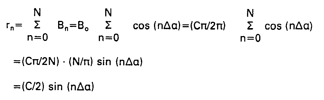


- Diese Funktion a=f(rn) ist für N=12 in Figur 7 dargestellt.
- Erfindungsgemäß wird weiter vorgeschlagen, anstelle eines Abtastfeldes G mit N Teilfeldern Fn' die unterschiedliche Breiten Bn und einen konstanten gegenseitigen Versatz Δα=π/N aufweisen, ein Abtastfeld G' mit M Teilfeldern F'm mit konstanter Breite B' vorzusehen, die gegeneinander jedoch einen variablen Versatz aufweisen, der so bemessen ist, daß die Mitten der Teilfelder Fm' auf der gleichen Linie liegen, die durch die Funktion a=arc sin (2rm/C) für N→ ∞ gebildet wird (m=0, 1, 2, ..., (M-1); M≧N; M=ungerade Zahl).
- Für den Abstand rm der Mitte des m-ten Teilfeldes Fm' mit der konstanten Breite B'=k · P (k=ganze Zahl) von der Mitte des Abtastfeldes G' gilt somit:


- Mit C≈kP(M-1 ) und arc sin (2rm/C)≈arc sin (2Pkm/C) ergibt sich:


- In Figur 4 ist ebenfalls der Maßstab M gemäß Figur 2 vergrößert dargestellt, dessen Teilung T mit der Teilungsperiode P mittels einer Abtastplatte AP' abgetastet wird. Das aus der Teilung T gewonnene periodische Analogsignal S(x) habe die Bandbreite N. Erfindungsgemäß sind daher zur Gewinnung eines ersten oberwellenfreien periodischen Analogsignals in Form des ersten Fouierkoeffizienten a, der Grundwelle des periodischen Analogsignals S(x) eine erste Abtastgruppe Ga' mit einem ersten Abtastfeld Ga1' und mit einem zweiten Abtastfeld Ga2' und zur Gewinnung eines zweiten oberwellenfreien periodischen Analogsignals in Form des zweiten Fourierkoeffizienten b1 der Grundwelle des periodischen Analogsignals S(x) eine zweite Abtastgruppe Gb' mit einem ersten Abtastfeld Gb1' und mit einem zweiten Abtastfeld Gb2' auf der Abtastplatte AP' angeordnet.
- Jedes Abtastfeld Ga1', Ga2', Gb1' . Gb2' der beiden Abtastgruppen Ga', Gb' besteht aus M Teilfeldern F alm', Fa2m', Fb1m', Fb2m' [m=0,1,2,..., (M-1); M≧N). Die Teilfelder Fa1m', Fa2m', Fb1m', Fb2m' weisen jeweils eine mit der Teilung T des Maßstabs M identische Teilung und in Meßrichtung x eine konstante Breite B'=kP (k=ganze Zahl) auf. Gemäß Figur 4 beträgt die Breite B' der Teilfelder Fa1m', Fa2m', Fb1m', Fb2m' eine Teilungsperiode P der Teilung T des Maßstabs M (k=1).
- Die Teilfeldmitten Malm', Ma2m', Mb1m', Mb2m' der Teilfelder Falm', Fa2m', Fb1m,', Fb2m' sind zur Abtastfeldmitte Ma1', Ma2', Mb1', Mb2' der zugehörigen Abtastfelder Ga1' Ga2', Gb1', Gb2' in Meßrichtung x um die Abstände rm=P[k · m+(1/2n) arc sin (2m/(M-1 )))] versetzt. Die Abtastfeldmitten Ma1', Mb1' der ersten Abtastfelder Ga1', Gb1' sind gegen die Abtastfeldmitten Ma2' , Mb2' der zweiten Abtastfelder Ga2' , Gb2' um die halbe Teilungsperiode P der Teilung T des Maßstabes M in Meßrichtung x versetzt; die erste Abtastgruppe Ga' ist gegen die zweite Abtastgruppe Gb' um ein Viertel der Teilungsperiode P der Teilung T des Maßstabs M in Meßrichtung x versetzt.
- Dem ersten Abtastfeld Gal' der ersten Abtastgruppe Ga' ist gemäß Figur 6a ein erstes Photoelement Pa1' und dem zweiten Abtastfeld Ga2' ein zweites Photoelement Pa2' zugeordnet, die antiparallel (in Differenz) geschaltet sind. Das oberwellenfreie Ausgangssignal ASa' der beiden antiparallel geschalteten Photoelemente Pa1', Pa2' ist proportional zum ersten Fourierkoeffizienten a1 der Grundwelle des periodischen Analogsignals S(x) und wird gemäß Figur 6b einer Auswerteeinrichtung W' zur Bildung von Positionsmeßwerten PM' zugeleitet, die in einer nachgeschalteten Anzeigeeinheit Z' angezeigt werden können.
- Dem ersten Abtastfeld Gb1' der zweiten Abtastgruppe Gb' ist gemäß Figur 6a ein erstes Photoelement Pb1' und dem zweiten Abtastfeld Gb2' ein zweites Photoelement Pb2' zugeordnet, die antiparallel (in Differenz) geschaltet sind. Das oberwellenfreie Ausgangssignal ASb' der beiden antiparallel geschalteten Photoelemente Pb1', Pb2' ist proportional zum zweiten Fourierkoeffizienten b1 der Grundwelle des periodischen Analogsignals S(x) und wird gemäß Figur 6b ebenfalls der Auswerteeinrichtung W' zur Bildung von Positionsmeßwerten PM' zugeleitet, die in der nachgeschalteten Anzeigeeinheit Z' angezeigt werden können. Die Auswerteeinrichtungen W, W' können zur Bildung von Positionsmeßwerten PM, PM' einen Richtungsdiskriminator zur Erkennung der Meßrichtung x aufweisen, der an einen Vorwärts-/ Rückwärtszähler angeschlossen ist. Gleichfalls können die Auswerteeinrichtungen W, W' eine zusätzliche Interpolationseinrichtung zur Bildung von interpolierten Positionsmeßwerten innerhalb der Teilungsperiode P der Teilung T des Maßstabs M aufweisen.
- Die Erfindung ist nicht auf lichtelektrische Positionsmeßeinrichtungen beschränkt, sondern auch bei magnetischen, induktiven und kapazitiven Positionsmeßeinrichtungen mit Erfolg einsetzbar.
Claims (8)
Priority Applications (1)
| Application Number | Priority Date | Filing Date | Title |
|---|---|---|---|
| AT85102216T ATE56091T1 (de) | 1984-03-31 | 1985-02-28 | Positionsmesseinrichtung. |
Applications Claiming Priority (2)
| Application Number | Priority Date | Filing Date | Title |
|---|---|---|---|
| DE3412128 | 1984-03-31 | ||
| DE3412128A DE3412128C1 (de) | 1984-03-31 | 1984-03-31 | Positionsmesseinrichtung |
Publications (3)
| Publication Number | Publication Date |
|---|---|
| EP0157177A2 EP0157177A2 (de) | 1985-10-09 |
| EP0157177A3 EP0157177A3 (en) | 1987-09-16 |
| EP0157177B1 true EP0157177B1 (de) | 1990-08-29 |
Family
ID=6232287
Family Applications (1)
| Application Number | Title | Priority Date | Filing Date |
|---|---|---|---|
| EP85102216A Expired - Lifetime EP0157177B1 (de) | 1984-03-31 | 1985-02-28 | Positionsmesseinrichtung |
Country Status (5)
| Country | Link |
|---|---|
| US (1) | US4602436A (de) |
| EP (1) | EP0157177B1 (de) |
| JP (1) | JPS60219511A (de) |
| AT (1) | ATE56091T1 (de) |
| DE (2) | DE3412128C1 (de) |
Cited By (4)
| Publication number | Priority date | Publication date | Assignee | Title |
|---|---|---|---|---|
| WO1991010288A3 (en) * | 1990-01-03 | 1991-11-28 | March Adrian Res Ltd | Position sensor |
| DE4323624A1 (de) * | 1993-07-15 | 1995-01-19 | Heidenhain Gmbh Dr Johannes | Lichtelektrische Längen- oder Winkelmeßeinrichtung |
| DE4323712A1 (de) * | 1993-07-15 | 1995-01-19 | Heidenhain Gmbh Dr Johannes | Lichtelektrische Längen- oder Winkelmeßeinrichtung |
| US5874729A (en) * | 1996-07-16 | 1999-02-23 | Johannes Heidenhain Gmbh | Device for filtering odd-numbered harmonic signal components |
Families Citing this family (32)
| Publication number | Priority date | Publication date | Assignee | Title |
|---|---|---|---|---|
| DE3616144A1 (de) * | 1986-05-14 | 1987-11-19 | Heidenhain Gmbh Dr Johannes | Fotoelektrische messeinrichtung |
| DE8613887U1 (de) * | 1986-05-22 | 1990-09-13 | Dr. Johannes Heidenhain Gmbh, 83301 Traunreut | Meßeinrichtung |
| DE3621236A1 (de) * | 1986-06-25 | 1988-01-14 | Heidenhain Gmbh Dr Johannes | Laengen- oder winkelmesseinrichtung |
| US4991125A (en) * | 1989-04-19 | 1991-02-05 | Mitutoyo Corporation | Displacement detector |
| DE3942178A1 (de) * | 1989-08-08 | 1991-02-21 | Heidenhain Gmbh Dr Johannes | Laengen- oder winkelmesseinrichtung |
| EP0513427B1 (de) * | 1991-05-18 | 1994-07-06 | Dr. Johannes Heidenhain GmbH | Interferentielle Positionsmessvorrichtung |
| EP0541827B1 (de) * | 1991-11-04 | 1995-04-12 | Dr. Johannes Heidenhain GmbH | Vorrichtung zur Erzeugung oberwellenfreier periodischer Signale |
| EP0541828B1 (de) * | 1991-11-04 | 1995-02-01 | Dr. Johannes Heidenhain GmbH | Vorrichtung zur Erzeugung oberwellenfreier periodischer Signale |
| US5173602A (en) * | 1991-12-24 | 1992-12-22 | Xerox Corporation | Binary position sensitive detector with multiple rows of alternating types of photocells |
| DE59201199D1 (de) * | 1992-02-14 | 1995-02-23 | Heidenhain Gmbh Dr Johannes | Wegmesseinrichtung. |
| DE4229575C1 (de) * | 1992-09-04 | 1993-11-25 | Heidenhain Gmbh Dr Johannes | Verfahren bei Längen- oder Winkelmeßeinrichtungen |
| DE59306689D1 (de) * | 1993-08-07 | 1997-07-10 | Heidenhain Gmbh Dr Johannes | Vorrichtung zur Erzeugung oberwellenfreier periodischer Signale |
| DE19508700C1 (de) * | 1995-03-02 | 1996-08-14 | Huebner Elektromasch Ag | Vorrichtung zum Gewinnen weitgehend oberwellenfreier periodischer Signale |
| US5590059A (en) * | 1995-03-14 | 1996-12-31 | Schier; J. Alan | Position encoder system which utilites the fundamental frequency of a ruled scale on an object |
| DE19511068A1 (de) * | 1995-03-25 | 1996-09-26 | Heidenhain Gmbh Dr Johannes | Lichtelektrische Positionsmeßeinrichtung |
| DE59508231D1 (de) * | 1995-06-22 | 2000-05-31 | Heidenhain Gmbh Dr Johannes | Positionsmesseinrichtung |
| DE19530560A1 (de) * | 1995-08-19 | 1997-02-20 | Ct Fuer Intelligente Sensorik | Längen- oder Winkelmeßeinrichtung |
| DE19532246A1 (de) * | 1995-09-01 | 1997-03-06 | Heidenhain Gmbh Dr Johannes | Vorrichtung zur Filterung von Oberwellen-Signalanteilen |
| DE19652562C2 (de) * | 1996-12-17 | 1999-07-22 | Heidenhain Gmbh Dr Johannes | Positionsmeßeinrichtung |
| US6327791B1 (en) | 1999-06-09 | 2001-12-11 | The Government Of The United States As Represented By The Secretary Of Commerce | Chain code position detector |
| EP1192412A4 (de) * | 1999-06-16 | 2003-05-14 | Snorkel International Inc | Kettenkode-positionsdetektor |
| DE19941318A1 (de) | 1999-08-31 | 2001-03-15 | Heidenhain Gmbh Dr Johannes | Optische Positionsmeßeinrichtung |
| DE10020575A1 (de) | 2000-04-28 | 2001-10-31 | Heidenhain Gmbh Dr Johannes | Abtasteinheit für eine optische Positionsmesseinrichtung |
| GB0506358D0 (en) * | 2004-09-29 | 2005-05-04 | Nanomotion Ltd | Assembly |
| DE102005009043A1 (de) * | 2005-02-22 | 2006-08-31 | Dr. Johannes Heidenhain Gmbh | Abtasteinheit für eine Positionsmesseinrichtung |
| JP5591754B2 (ja) * | 2005-03-30 | 2014-09-17 | ナノモーション エルティーディー. | 台の搬送システム |
| EP1795873B1 (de) | 2005-12-06 | 2017-11-08 | Mitutoyo Corporation | Fotoelektrischer Kodierer |
| KR101133817B1 (ko) * | 2007-06-18 | 2012-04-06 | 인텔 코포레이션 | 집합 패킷들의 통신을 위한 장치, 방법 및 시스템 |
| GB201301186D0 (en) | 2012-12-20 | 2013-03-06 | Renishaw Plc | Optical element |
| JP2014224705A (ja) * | 2013-05-15 | 2014-12-04 | キヤノン株式会社 | スケール保持装置、およびエンコーダ |
| JP6359340B2 (ja) * | 2014-05-27 | 2018-07-18 | 株式会社ミツトヨ | スケール及び光学式エンコーダ |
| JP6747568B1 (ja) * | 2019-11-18 | 2020-08-26 | セイコーエプソン株式会社 | 液体吐出装置および液体吐出ヘッドユニット |
Family Cites Families (12)
| Publication number | Priority date | Publication date | Assignee | Title |
|---|---|---|---|---|
| DE1282988B (de) * | 1965-05-28 | 1968-11-14 | Zeiss Carl Fa | Einrichtung zum Messen von Lageaenderungen zweier zueinander beweglicher Teile unterVerwendung einer inkohaerenten Strahlung |
| US3578979A (en) * | 1968-04-23 | 1971-05-18 | Tajima Seisakusho Kk | Electrical signal generating apparatus having a scale grid |
| DE1941731C2 (de) * | 1969-08-16 | 1973-11-15 | Fa. Carl Zeiss, 7920 Heidenheim | Einrichtung zur Messung von Lageande rungen zweier relativ zueinander bewegli eher Teile |
| US3713139A (en) * | 1971-01-25 | 1973-01-23 | Bendix Corp | Apparatus and method of determining displacements |
| DE2207132A1 (de) * | 1972-02-16 | 1973-08-30 | Heidenhain Gmbh Dr Johannes | Anordnung zum messen der relativlage zweier zueinander beweglicher teile |
| US4078173A (en) * | 1976-06-24 | 1978-03-07 | Pertec Computer Corporation | Light amplitude control system for position and motion transducers |
| DE2729697A1 (de) * | 1977-07-01 | 1979-01-04 | Heidenhain Gmbh Dr Johannes | Verfahren zur interpolation |
| DE2826213B2 (de) * | 1978-06-15 | 1980-06-04 | Dr. Johannes Heidenhain Gmbh, 8225 Traunreut | Photoelektrisches inkrementales Längen- und Winkelmeßsystem |
| DE3104972C2 (de) * | 1981-02-12 | 1985-06-20 | Dr. Johannes Heidenhain Gmbh, 8225 Traunreut | Lichtelektrische inkrementale Positioniereinrichtung |
| JPS57169613A (en) * | 1981-04-13 | 1982-10-19 | Tokyo Optical Co Ltd | Photoelectric encoder |
| DE3148910C1 (de) * | 1981-12-10 | 1983-03-10 | Dr. Johannes Heidenhain Gmbh, 8225 Traunreut | Lichtelektrische inkrementale Laengen- oder Winkelmesseinrichtung |
| DE3509102C2 (de) * | 1985-03-14 | 1987-01-15 | Dr. Johannes Heidenhain Gmbh, 8225 Traunreut | Meßeinrichtung |
-
1984
- 1984-03-31 DE DE3412128A patent/DE3412128C1/de not_active Expired
-
1985
- 1985-02-28 DE DE8585102216T patent/DE3579338D1/de not_active Expired - Fee Related
- 1985-02-28 EP EP85102216A patent/EP0157177B1/de not_active Expired - Lifetime
- 1985-02-28 AT AT85102216T patent/ATE56091T1/de not_active IP Right Cessation
- 1985-03-19 US US06/713,458 patent/US4602436A/en not_active Expired - Lifetime
- 1985-03-28 JP JP60062218A patent/JPS60219511A/ja active Granted
Cited By (4)
| Publication number | Priority date | Publication date | Assignee | Title |
|---|---|---|---|---|
| WO1991010288A3 (en) * | 1990-01-03 | 1991-11-28 | March Adrian Res Ltd | Position sensor |
| DE4323624A1 (de) * | 1993-07-15 | 1995-01-19 | Heidenhain Gmbh Dr Johannes | Lichtelektrische Längen- oder Winkelmeßeinrichtung |
| DE4323712A1 (de) * | 1993-07-15 | 1995-01-19 | Heidenhain Gmbh Dr Johannes | Lichtelektrische Längen- oder Winkelmeßeinrichtung |
| US5874729A (en) * | 1996-07-16 | 1999-02-23 | Johannes Heidenhain Gmbh | Device for filtering odd-numbered harmonic signal components |
Also Published As
| Publication number | Publication date |
|---|---|
| DE3579338D1 (de) | 1990-10-04 |
| DE3412128C1 (de) | 1985-05-09 |
| EP0157177A2 (de) | 1985-10-09 |
| JPS60219511A (ja) | 1985-11-02 |
| US4602436A (en) | 1986-07-29 |
| EP0157177A3 (en) | 1987-09-16 |
| ATE56091T1 (de) | 1990-09-15 |
| JPH0125009B2 (de) | 1989-05-16 |
Similar Documents
| Publication | Publication Date | Title |
|---|---|---|
| EP0157177B1 (de) | Positionsmesseinrichtung | |
| DE3239108C2 (de) | ||
| DE3616144C2 (de) | ||
| DE3334398C1 (de) | Messeinrichtung | |
| DE3417176A1 (de) | Photoelektrische messeinrichtung | |
| EP0541827B1 (de) | Vorrichtung zur Erzeugung oberwellenfreier periodischer Signale | |
| DE10049368A1 (de) | Positionswandler mit positionsabhängiger Amplitudenkodierung | |
| EP0645607B1 (de) | Vorrichtung zur Erzeugung oberwellenfreier periodischer Signale | |
| EP0804716B1 (de) | Fotoelektrisches weg- und winkelmesssystem zum messen der verschiebung zweier objekte zueinander | |
| EP1995566B1 (de) | Maßstab für eine Positionsmesseinrichtung und Positionsmesseinrichtung | |
| EP0083689B1 (de) | Lichtelektrische inkrementale Längen- oder Winkelmesseinrichtung | |
| DE1941731B1 (de) | Einrichtung zur Messung von Lageaenderungen zweier relativ zueinander beweglicher Teile | |
| EP0541829B1 (de) | Vorrichtung zur Erzeugung oberwellenfreier periodischer Signale | |
| EP0763715B1 (de) | Vorrichtung zur Filterung von Oberwellen-Signalanteilen | |
| DD93037B1 (de) | Kapazitives weg- und winkelmesssystem | |
| DE3486351T2 (de) | Detektorkopf. | |
| EP0750179B1 (de) | Positionsmesseinrichtung | |
| DE4202560C2 (de) | Vorrichtung zur Erzeugung oberwellenfreier periodischer Signale | |
| DE4212281C2 (de) | ||
| EP0547270A1 (de) | Fotoelektrische Vorrichtung zur Erzeugung oberwellenfreier periodischer Signale | |
| DE102021005682A1 (de) | Optische Positionsmesseinrichtung | |
| DE3322738C1 (de) | Lichtelektrische Längen- oder Winkelmeßeinrichtung | |
| DE3720916C2 (de) | Maßverkörperung | |
| DE3906777A1 (de) | Verfahren zur messung eines drehwinkels und drehwinkelmesser | |
| DE3409298C1 (de) | Positionsmeßeinrichtung |
Legal Events
| Date | Code | Title | Description |
|---|---|---|---|
| PUAI | Public reference made under article 153(3) epc to a published international application that has entered the european phase |
Free format text: ORIGINAL CODE: 0009012 |
|
| 17P | Request for examination filed |
Effective date: 19850307 |
|
| AK | Designated contracting states |
Designated state(s): AT CH DE FR GB IT LI NL SE |
|
| PUAL | Search report despatched |
Free format text: ORIGINAL CODE: 0009013 |
|
| AK | Designated contracting states |
Kind code of ref document: A3 Designated state(s): AT CH DE FR GB IT LI NL SE |
|
| 17Q | First examination report despatched |
Effective date: 19881207 |
|
| RAP3 | Party data changed (applicant data changed or rights of an application transferred) |
Owner name: DR. JOHANNES HEIDENHAIN GMBH |
|
| ITF | It: translation for a ep patent filed | ||
| GRAA | (expected) grant |
Free format text: ORIGINAL CODE: 0009210 |
|
| AK | Designated contracting states |
Kind code of ref document: B1 Designated state(s): AT CH DE FR GB IT LI NL SE |
|
| REF | Corresponds to: |
Ref document number: 56091 Country of ref document: AT Date of ref document: 19900915 Kind code of ref document: T |
|
| ET | Fr: translation filed | ||
| GBT | Gb: translation of ep patent filed (gb section 77(6)(a)/1977) | ||
| REF | Corresponds to: |
Ref document number: 3579338 Country of ref document: DE Date of ref document: 19901004 |
|
| PGFP | Annual fee paid to national office [announced via postgrant information from national office to epo] |
Ref country code: SE Payment date: 19910128 Year of fee payment: 7 |
|
| PGFP | Annual fee paid to national office [announced via postgrant information from national office to epo] |
Ref country code: NL Payment date: 19910228 Year of fee payment: 7 |
|
| PLBE | No opposition filed within time limit |
Free format text: ORIGINAL CODE: 0009261 |
|
| STAA | Information on the status of an ep patent application or granted ep patent |
Free format text: STATUS: NO OPPOSITION FILED WITHIN TIME LIMIT |
|
| 26N | No opposition filed | ||
| PG25 | Lapsed in a contracting state [announced via postgrant information from national office to epo] |
Ref country code: SE Effective date: 19920301 |
|
| PG25 | Lapsed in a contracting state [announced via postgrant information from national office to epo] |
Ref country code: NL Effective date: 19920901 |
|
| NLV4 | Nl: lapsed or anulled due to non-payment of the annual fee | ||
| ITTA | It: last paid annual fee | ||
| EUG | Se: european patent has lapsed |
Ref document number: 85102216.0 Effective date: 19921005 |
|
| PGFP | Annual fee paid to national office [announced via postgrant information from national office to epo] |
Ref country code: AT Payment date: 20010124 Year of fee payment: 17 |
|
| PGFP | Annual fee paid to national office [announced via postgrant information from national office to epo] |
Ref country code: FR Payment date: 20010205 Year of fee payment: 17 |
|
| REG | Reference to a national code |
Ref country code: GB Ref legal event code: IF02 |
|
| PGFP | Annual fee paid to national office [announced via postgrant information from national office to epo] |
Ref country code: CH Payment date: 20020117 Year of fee payment: 18 |
|
| PGFP | Annual fee paid to national office [announced via postgrant information from national office to epo] |
Ref country code: GB Payment date: 20020222 Year of fee payment: 18 |
|
| PG25 | Lapsed in a contracting state [announced via postgrant information from national office to epo] |
Ref country code: AT Free format text: LAPSE BECAUSE OF NON-PAYMENT OF DUE FEES Effective date: 20020228 |
|
| PG25 | Lapsed in a contracting state [announced via postgrant information from national office to epo] |
Ref country code: FR Free format text: LAPSE BECAUSE OF NON-PAYMENT OF DUE FEES Effective date: 20021031 |
|
| REG | Reference to a national code |
Ref country code: FR Ref legal event code: ST |
|
| PGFP | Annual fee paid to national office [announced via postgrant information from national office to epo] |
Ref country code: DE Payment date: 20030208 Year of fee payment: 19 |
|
| PG25 | Lapsed in a contracting state [announced via postgrant information from national office to epo] |
Ref country code: LI Free format text: LAPSE BECAUSE OF NON-PAYMENT OF DUE FEES Effective date: 20030228 Ref country code: GB Free format text: LAPSE BECAUSE OF NON-PAYMENT OF DUE FEES Effective date: 20030228 Ref country code: CH Free format text: LAPSE BECAUSE OF NON-PAYMENT OF DUE FEES Effective date: 20030228 |
|
| GBPC | Gb: european patent ceased through non-payment of renewal fee | ||
| REG | Reference to a national code |
Ref country code: CH Ref legal event code: PL |
|
| PG25 | Lapsed in a contracting state [announced via postgrant information from national office to epo] |
Ref country code: DE Free format text: LAPSE BECAUSE OF NON-PAYMENT OF DUE FEES Effective date: 20040901 |