EP0155840B1 - Vorrichtung und Verfahren zum Verschaffen von Zugang zur Unterseite einer Brücke - Google Patents
Vorrichtung und Verfahren zum Verschaffen von Zugang zur Unterseite einer Brücke Download PDFInfo
- Publication number
- EP0155840B1 EP0155840B1 EP85301879A EP85301879A EP0155840B1 EP 0155840 B1 EP0155840 B1 EP 0155840B1 EP 85301879 A EP85301879 A EP 85301879A EP 85301879 A EP85301879 A EP 85301879A EP 0155840 B1 EP0155840 B1 EP 0155840B1
- Authority
- EP
- European Patent Office
- Prior art keywords
- tower
- support means
- platform
- cantilever
- bridge
- Prior art date
- Legal status (The legal status is an assumption and is not a legal conclusion. Google has not performed a legal analysis and makes no representation as to the accuracy of the status listed.)
- Expired
Links
Images


Classifications
-
- E—FIXED CONSTRUCTIONS
- E01—CONSTRUCTION OF ROADS, RAILWAYS, OR BRIDGES
- E01D—CONSTRUCTION OF BRIDGES, ELEVATED ROADWAYS OR VIADUCTS; ASSEMBLY OF BRIDGES
- E01D19/00—Structural or constructional details of bridges
- E01D19/10—Railings; Protectors against smoke or gases, e.g. of locomotives; Maintenance travellers; Fastening of pipes or cables to bridges
- E01D19/106—Movable inspection or maintenance platforms, e.g. travelling scaffolding or vehicles specially designed to provide access to the undersides of bridges
Definitions
- This invention relates to apparatus for providing access to the underside of a bridge deck.
- Aprincipal method of demolishing a bridge is to fix a charge securing system to the underside of the deck of the bridge to which demolition charges can be attached for subsequent detonation. It is necessary for personnel to gain access to the underside of the bridge deck in orderto place these demolition components.
- Several methods of providing the required access are known. Some rely on gaining access from the grounds beneath the bridge, for example by ladders or vehicles with elevatable platforms, but these are not usable if the bridge is too high or spans inaccessible ground or a waterway for example.
- an alternative method that has been adopted, which has the advantage of being usable with most bridge designs is to build a scaffold structure on the bridge deck to support a platform beneath it.
- the main disadvantage of this system is that it involves a lengthy construction process which is not suited to operations where speed of deployment is of great importance.
- German Patent Specification DE-A-3305384 there is disclosed an apparatus for providing access to the underside of a bridge deck, which consists of a support means positionable on the bridge deck, a tower support means rotatably mountable on the support means, a tower engageable with the tower support means, a platform support means rotatably mountable on the tower, and a platform engageable with the platform support means.
- Engagement of the tower with the tower support means is such as to allow the tower to be moved longitudinally relative thereto whilst being supported thereby and to be rotatable into a substantially vertical position adjacent the bridge deck, whereas engagement of the platform with the platform support means is such as to allow the platform to be supported thereby at a first position substantially parallel to the tower and to be rotatable from the first position to a second position substantially perpendicularto the tower to locate the platform under the bridge deck when the tower is in its substantially vertical position.
- the tower support means disclosed in DE-A-3305384 consists of a guide box for the tower which is swivel mounted on a carriage by means of a ring mounting around an axis running horizontally in a direction outwards from the bridge deck.
- the tower, to which the platform is pivotally connected initially in a parallel relationship thereto, is deployed in its vertical position by first moving the carriage on its support sideways until the tower is suspended horizontally over the side of the bridge perpendicular to the axis of the ring mounting, whereafter the guide box is swivelled into a vertical position and thetower lowered through the box to an appropriate ' position for deploying the platform.
- platform support means comprises two mutually orthogonal pivotable elements; a cross-shaft on the bottom of the tower which allows the platform to be rotated about a horizontal axis from its vertical position parallel to the tower to a horizontal position alongside the bridge deck, and a ring mounting which allows the platform to be subsequently rotated about a vertical axis until it is positioned underneath the bridge deck.
- the tower support means comprises a first cantilever support means engageable with the tower so as to allow the tower to be cantilever launched outwardly from the bridge deck whilst being supported substantially horizontally by the first cantilever support means
- the platform support means comprises a second cantilever support means engageable with the platform so as to allow the platform at its first position to be cantilever launched therefrom outwardly from the bridge deck before the tower is launched.
- An apparatus according to the invention is hereinafter referred to as an under-bridge access assembly.
- the first support means When deployed, the first support means supports the tower vertically down the side of the bridge-deck with the platform in turn supported horizontally beneath the bridge-deck by the second cantilever means mounted on the tower. Access is gained to the underside of the bridge deck by climbing down the tower and onto and along the platform.
- the platform may conveniently be engaged with the second cantilever support means before the tower is launched over the side of the bridge-deck by being moved relative to the first cantilever support means.
- the tower When the tower has been advanced sufficiently far it may then be rotated into a substantially vertical position adjacent the side of the bridge-deck at the same time bringing the platform into position beneath the bridge-deck.
- the engagement of the platform with the second cantilever support means allows the platform to be moved relative thereto whilst being supported substantially horizontally so that the horizontal position of the platform relative to the tower can be varied. If, for example, stores needed to be lowered to the personnel on the platform, the platform can be adjusted so that a portion extends from the tower in a direction away from the underside of the bridge deck to receive those stores.
- the tower may be engaged with the first cantilever support means with the second cantilever support means locked in the first position.
- the platform may then be engaged with the second cantilever support means and moved relative to it whilst being supported thereby launching the platform over the side of the bridge-deck.
- the second cantilever support means may then be unlocked from its first position and rotated to, and locked in, its second position thus bringing the platform substantially perpendicular to the tower.
- the tower may then be launched and rotated, as described above, to deploy the platform beneath the bridge-deck.
- the first cantilever support means may conveniently be fixed relative to the support means during deployment and retrieval of the under- bridge access assembly, the tower being rotatable from a horizontal position to a vertical position by means of a pivot frame, engageable with the first cantilever support means and rotatably attachable to the tower.
- Both the platform and the tower may conveniently comprise a series of modules interengageable end to end so that each module may be jointed in turn to the preceeding one as it is fed into the first or second cantilever support means.
- Various length modules may conveniently be provided to allow the length of the platform and tower to be matched to the dimensions of the particular bridge to be demolished.
- the modules are conveniently of an open truss construction and of trapezoidal cross section so that they are light and can be stacked within each other for compact transportation.
- the support means may conveniently be a support pillar so as to provide a compact means of maintaining the first cantilever support means in the appropriate position on the bridge deck during deployment.
- the support pillar may be provided with a removable counterweight base beam having a ramp arranged so that a vehicle parked with its wheels on the ramp will stabilise the support pillar during deployment of the under-bridge access assembly. This permits deployment without damaging the bridge which is particularly important for use of the assembly during peacetime training. If a flat decked vehicle is used to transport the modules, its deck can be used for construction of a platform and tower whilst simultaneously stabilising the support pillar.
- a--single under bridge access assembly If a--single under bridge access assembly is deployed, the end of the platform furthest from the second cantilever support means should be supported beneath the bridge for added security-conveniently by a cable attached to the bridge parapet furthest from the support tower.
- two underbridge access assemblies may be deployed, one from each bridge parapet, and the two free ends of the platforms joined together by a linking module.
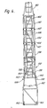
- FIG. 1 there is shown an under-bridge access assembly 2 fully deployed on a bridge deck 4 having a cambered road surface 6, a first and a second pedestrian way 8 and 10, and two parapets 12, 14, and an under-bridge deck 16.
- a launch frame 20 constituting the first cantilever support means, supported in position beside the parapet 12 by a support pillar 22 having a base 24 which rests on the pedestrian way 8 close to the parapet 12.
- the support pillar 22 is stabilised in a plane parallel to the plane of the parapet 12 by means of a pair of adjustable levelling struts 26 extending horizontally from the support pillar 22 which struts each have at their extremity a pad 28 fixed to a height-adjustable jack 30.
- the levelling struts 26 are pivotally attached to fixing plates 32 attached near the base 24 of the support pillar 22 at pivot joints 34 so that the struts 26 can be made to lie next to the support pillar 22 for easier transportation.
- the struts 26 are fixed in the extended position as shown in Figure 2 by fixing pins 36.
- the support pillar 22 is provided with stability in the vertical plane perpendicular to the plane of the parapet 12 during deployment of the under- bridge access assembly by means of a counterweight base beam 50 connected to a vertical plate 52 welded near the base of the support pillar 22 by a fixed length connecting arm 54.
- the support pillar 22 is maintained in a vertical position by means of a strut 56 pivotally attached to one of the plates 40 at the top of the support
- the counterweight base beam 50 comprises an open, rectangular framework 58 having four ramps 60 each hinged to the framework 58 so that they can be folded for ease of transportation.
- a lorry 61 ( Figure 1) can be driven up the ramps 60 so that a pair of its wheels 62 are positioned between side members 66 of the framework 58 as depicted in Figure 1.
- the weight of the lorry 61 provides stability to the support pillar 22 during deployment of the under bridge access assembly 2.
- the support pillar 22 and counterweight base beam 50 constitute the support means for the access assembly 2.
- the launch frame 20 has two main spars 70 and 72 joined by six cross-beams 74, 76, 78, 80, 82 and 84.
- the cross-beam pairs 76, 78 and 80, 82 are closely spaced and positioned so that four fixing bolts 86 can pass between the cross beam pairs to be located in fixing holes in the plate 38 thereby locating the launch frame 20 in position on the top of the support pillar 22.
- Two work platforms 88 and 90 are each hinged to the ends of the main spars 70 and 72 at hinged joints 92, each platform being provided with an outer safety rail 94.
- the ends of the main spars 70 and 72 terminate in perpendicular end plates 100 on which are located pairs of upper and lower rollers 102 and 104 which constitute the first cantilever support means.
- FIG. 4 there is shown a tower 130 as used in the under-bridge access assembly of Figure 1 consisting of tower modules 132,134, 136 and 138 connected end to end by pairs of hook joints 142 and pin joints 144.
- the tower modules 132 to 138 are of open truss construction each having two parallel rollerengagementflanges 146, all having a trapezoidal cross section to allowthem to be nested fortransportation.
- the tower module 132 is fitted with an open frame 150.
- Pivotally attached to the end tower module 138 is a cantilever frame 152 having two pairs of rollers 153, constituting the second cantilever support means, which (152) can be locked perpendicularto the tower 130 as shown in Figure 1 by a pair of locking pins 155 linking pairs of flanges 157 and 159 or substantially parallel to it as shown in Figure 5 by the pair of locking pins 155 linking pairs of flanges 154.and 156.
- the tower module 132 is pivotally attached to a pivot frame 160 by means of pins 163 constituting a connecting means, the frame 160 having side spars 162 engaged with the rollers 102 and 104 of the launch frame 20.
- a hand operated winch 164 with cable 165 attached to the pivot frame 160 and the frame 150 can be used to rotate the tower during deployment and retrieval.
- FIG. 1 the tower 130 is shown in its deployed, vertical position where it is maintained by a pair of bracing struts 166 fixed between the frame 150 ofthetower 130 andthe pivotframe 160.
- the tower modules 132 to 138 are each provided with a ladder section 168 (see Figure 4) so that when the tower 130 is in its deployed position personnel can climb down inside the tower 130 from the bridge deck 4.
- a platform 180 comprising a plurality of platform modules 182 connected end to end by hook and pin joints in the same manner as the tower modules are interconnected, is supported by the cantilever frame 152.
- the platform modules 182 are of open truss construction and of trapezoidal cross section to allowthem to be nested within one another for compactness during transportation. They are provided with decking 183 to permit personnel to walk along the platform 180 when it is deployed.
- Each platform module 182 is provided with drilled plates 184 to which a safety harness can be attached.
- An auxiliary staging unit 186 mounted on top of the platform 180 provides access when required above the reaching height of personnel on the platform 180.
- the decking 183 of the platform 180 is provided with spaced-apart holes to locate the bottom of a ladder (not shown) if needed to reach above the access level provided by the unit 186.
- the platform 180 as shown in Figure 1 has been advanced through the cantilever frame 152 until the end of the platform 180 furthest from the cantilever 152 is close to the parapet 14 on the far side of the bridge.
- a clamp 192 fixed to the parapet 14 supports a simple cable and pulley arrangement 190 which is attached to the end of the platform 180 to support the weight of the platform.
- the supporttower22 is unloaded from the lorry 61 and erected by deploying the struts 26 and adjusting the height of the jacks 30.
- the counterweight base beam 50 is then unloaded and connected to the base of the support tower by means of the connector 54.
- the lorry 61 is backed onto the counterweight base beam 50 and the strut 56 adjusted to maintain the support tower 22 in a vertical position.
- the launch frame 20 is now placed on top of the support tower 22 and bolted into position, the work platforms 88 and 90 folded down into position and the safety rails 94 fixed into place.
- the end-tower module 138 with the attached cantileverframe 152 isthen engaged with the launch frame 20.
- the cantilever frame 152 is locked into its first locked position parallel to the tower by means of first locking means 154, 155, 156 and a first platform module 182 is attached to cantilever frame 152.
- the remaining platform modules 182 are added one at a time by linking each one to the last platform module supported by the cantilever frame 152 and subsequently advancing the platform modules through the rollers 153 thereby cantilevering out the rest of the platform 180.
- the platform is locked into its second locked position relative to the frame 152 by means of simple pins 151 which pass through flanges 149 fixed to the frame 152 and the drilled plates 184 of the last- launched platform module 182 after which the cantilever frame 152 is rotated through a little more than 90° thereby bringing the platform into its second locked, vertical position down the side of the parapet 12 where it is fixed in position by the pins 155 linking pairs of flanges 157 and 159.
- tower modules 132 to 136 may now be linked in sequence to the tower module 138 and cantilevered-out from the launch frame 20 in a similar manner to the way in which the platform 180 was cantilevered-out from the cantilever frame 152.
- the final tower module 132 with the frame 150 is connected when it together with the modules that have already been launched covers the distance between the launch frame 20 and the bottom of the parapet 12.
- the pivot frame 160 is then pivotally linked to the tower module 132 by the pivot pins 163 and maintained in alignment with the pivot frame 160 by means of the hand winch 164 linking the pivot frame 160 to the frame 150 of the tower module 132.
- the tower 130 is then advanced through the launch frame 20 until the pivot frame 160 is engaged with the rollers 102 and 104 of the launching frame 20 and the pivot pins 163 overhang the parapet 12.
- the tower 130 may now be pivoted into a vertical position by letting out the cable 165 from the winch 164.
- the tower 130 When the tower 130 is in a vertical position it is secured in position by means of the pair of bracing struts 166.
- the platform 180 is now positioned horizontally and parallel to the underside 16 of the bridge deck.
- the clamp 192 is then clamped to the parapet wall 14 on the other side of the bridge deck from the support tower 22 and the support cable arrangement 190 attached to the free end of the platform 180.
- the winch assembly 164 is now removed as are the lorry 61 and the counterweight base beam 50 thereby freeing access to the roadway 6.
- each platform 180 can be positioned so that part of it extends from the tower in the direction away from the parapet 12. This provides a platform on to which stores can be lowered from a pulley (not shown) attached to the top of the tower module 132.
- the platform 180 may be provided with side netting in order to prevent the loss of stores from the platform 180.
Landscapes
- Engineering & Computer Science (AREA)
- Architecture (AREA)
- Civil Engineering (AREA)
- Structural Engineering (AREA)
- Bridges Or Land Bridges (AREA)
Claims (7)
Applications Claiming Priority (2)
| Application Number | Priority Date | Filing Date | Title |
|---|---|---|---|
| GB8407141 | 1984-03-19 | ||
| GB848407141A GB8407141D0 (en) | 1984-03-19 | 1984-03-19 | Under-bridge access assembly |
Publications (3)
| Publication Number | Publication Date |
|---|---|
| EP0155840A2 EP0155840A2 (de) | 1985-09-25 |
| EP0155840A3 EP0155840A3 (en) | 1986-06-25 |
| EP0155840B1 true EP0155840B1 (de) | 1989-04-26 |
Family
ID=10558326
Family Applications (1)
| Application Number | Title | Priority Date | Filing Date |
|---|---|---|---|
| EP85301879A Expired EP0155840B1 (de) | 1984-03-19 | 1985-03-18 | Vorrichtung und Verfahren zum Verschaffen von Zugang zur Unterseite einer Brücke |
Country Status (4)
| Country | Link |
|---|---|
| US (1) | US4633975A (de) |
| EP (1) | EP0155840B1 (de) |
| DE (1) | DE3569767D1 (de) |
| GB (1) | GB8407141D0 (de) |
Families Citing this family (16)
| Publication number | Priority date | Publication date | Assignee | Title |
|---|---|---|---|---|
| DE8903771U1 (de) * | 1989-03-25 | 1990-07-26 | Moog, Alfons, 7774 Deggenhausertal, De | |
| FR2650815B1 (fr) * | 1989-08-11 | 1991-11-29 | France Etat Ponts Chaussees | Materiel d'inspection visuelle des faces et parois d'un ouvrage de grandes dimensions |
| US5014381A (en) * | 1989-09-18 | 1991-05-14 | Eddy Jack E | Rolling platform assembly |
| US5549176A (en) * | 1994-09-09 | 1996-08-27 | Modern Bridge Forming Co., Inc. | Bridge construction machinery and method for constructing bridges |
| US6598702B1 (en) | 2000-07-13 | 2003-07-29 | Mcgillewie, Jr. Garth E. | Under bridge access apparatus with cross-linking member connecting tower with vehicular chassis |
| FR2821638B1 (fr) * | 2001-03-01 | 2005-01-14 | Frederic Desneux | Equipement pour la restauration, le nettoyage et/ou la mise en place d'equipements divers sur des parois verticales et/ou sous des voutes d'un ouvrage |
| US7014011B1 (en) * | 2004-01-30 | 2006-03-21 | Honore Ivory Alexander | Scaffolding lift system |
| US7128186B2 (en) * | 2004-05-18 | 2006-10-31 | Jeff Ganiere | Airport bridge people lift |
| FI20135815L (fi) * | 2013-08-06 | 2015-02-07 | Fast Beam Oy | Teline |
| US9695024B2 (en) * | 2015-01-23 | 2017-07-04 | Jeremy Herauf | Unique roadworthy sidewalk boom trailer, having on-site interchangeable boom, on-site interchangeable ladder, and on-site interchangeable catwalk sized to access narrow openings and nooks over and under bridges |
| CN105178178B (zh) * | 2015-07-23 | 2017-10-10 | 中铁第五勘察设计院集团有限公司 | 一种可过墩式桥梁检查设备 |
| CN106968172B (zh) * | 2016-01-13 | 2019-12-17 | 陕西汽车集团有限责任公司 | 桁架式桥梁检测车的防倾翻装置 |
| JP6261800B1 (ja) * | 2017-07-12 | 2018-01-17 | 日本ビソー株式会社 | 作業用ゴンドラ装置およびこれを備えた作業用車両 |
| CN108277740A (zh) * | 2018-01-19 | 2018-07-13 | 江苏森淼工程质量检测有限公司 | 一种桥梁检测车工作台荷载超限保护装置及其控制方法 |
| CN112854064B (zh) * | 2019-11-27 | 2022-04-12 | 怀化市恒裕实业有限公司 | 一种防卡头安全道路护栏 |
| CN112813819A (zh) * | 2021-01-07 | 2021-05-18 | 刘帅 | 一种稳定性好的桥梁检测活动平台 |
Family Cites Families (12)
| Publication number | Priority date | Publication date | Assignee | Title |
|---|---|---|---|---|
| US2598730A (en) * | 1948-03-03 | 1952-06-03 | John L Thompson | Portable dock scaffold |
| US3145801A (en) * | 1963-04-23 | 1964-08-25 | Frederick S Callahan | Scaffold staging |
| US3197178A (en) * | 1964-01-08 | 1965-07-27 | Donald H Nietz | Apparatus for installing continuous rows of fluorescent lighting fixtures |
| DE2054646A1 (de) * | 1969-11-12 | 1971-08-26 | Colbacchini, Attiho D , Chiarotto, Romeo, Dr , Lotto, Sergio, Dr Ing , Saggin, Francesco, Dr Ing , Padova (Italien) | Bruckenbesichtigungseinnchtung |
| US3608669A (en) * | 1969-12-02 | 1971-09-28 | Bridge Painting Inc | Bridge-painting apparatus and method |
| US3900080A (en) * | 1974-08-15 | 1975-08-19 | Jones Spencer D | Scaffold apparatus |
| GB1517560A (en) * | 1974-11-22 | 1978-07-12 | Sverre Munck As | Maintenance of platform deck structures |
| US3995250A (en) * | 1975-11-05 | 1976-11-30 | Ferree Robert W | Portable traffic signal light |
| IT1059351B (it) * | 1976-02-27 | 1982-05-31 | Fip Formatura Inienzione Poli | Struttura reticolare telescopica e snodata autotrasportata ed auto varante particolarmente adatta per ispezione e manutenzione di opere d arte stradali |
| IT1123032B (it) * | 1976-11-09 | 1986-04-30 | Autostrade Concess Const | Ponteggio sospeso retrattile su carrello semovente particolarmente atto per interventi di manutenzione sui ponti stradali e simili |
| FR2438711A1 (fr) * | 1978-10-12 | 1980-05-09 | Pechiney Aluminium | Echafaudage de visite repliable |
| DE3305384A1 (de) * | 1982-09-14 | 1984-03-15 | Alfons 7774 Deggenhausertal Moog | Einrichtung zur inspektion der unterseite von bruecken |
-
1984
- 1984-03-19 GB GB848407141A patent/GB8407141D0/en active Pending
-
1985
- 1985-03-14 US US06/711,493 patent/US4633975A/en not_active Expired - Lifetime
- 1985-03-18 DE DE8585301879T patent/DE3569767D1/de not_active Expired
- 1985-03-18 EP EP85301879A patent/EP0155840B1/de not_active Expired
Also Published As
| Publication number | Publication date |
|---|---|
| DE3569767D1 (en) | 1989-06-01 |
| US4633975A (en) | 1987-01-06 |
| EP0155840A3 (en) | 1986-06-25 |
| GB8407141D0 (en) | 1984-04-26 |
| EP0155840A2 (de) | 1985-09-25 |
Similar Documents
| Publication | Publication Date | Title |
|---|---|---|
| EP0155840B1 (de) | Vorrichtung und Verfahren zum Verschaffen von Zugang zur Unterseite einer Brücke | |
| US7971408B2 (en) | Stairtower and method for erecting the same | |
| US7025546B2 (en) | Vehicle support frame | |
| EP0214345B1 (de) | Ausdehnbarer Steg | |
| US5622237A (en) | Portable hoist system | |
| US20160344330A1 (en) | Portable Solar Power System with Prefabricated Solar Racking | |
| CN1151197A (zh) | 脚手架组件 | |
| US4660680A (en) | Means and methods for erecting a work platform under the deck of a structure | |
| CA2567141A1 (en) | Modular multilevel access platform and method for erecting the same | |
| US4972538A (en) | Launching apparatus for transportable bridges | |
| HUE025649T2 (en) | Scaffolding | |
| US6527081B1 (en) | Embankment stairway | |
| EP0038361A4 (de) | Einklappbares gerüstsystem. | |
| EP0142963B1 (de) | Gerüst | |
| EP0419250A2 (de) | Ladebühne für ein Gebäude im Bau | |
| US20040144594A1 (en) | Work platform | |
| US4663793A (en) | Methods of deploying a bridge of a particular construction | |
| CA2946063A1 (en) | Land-based rig with on-board crane | |
| US4665577A (en) | Methods of constructing modular bridges | |
| EP0165712B1 (de) | Brückenkonstruktion | |
| CA2482342A1 (en) | Work platform | |
| GB2196674A (en) | Transportable bridges | |
| EP0392641A1 (de) | Brückenkonstruktion | |
| WO2001053630A1 (en) | Temporary access structures | |
| EP2872694B1 (de) | Mobile brücke und verfahren zur errichtung einer solchen mobilen brücke |
Legal Events
| Date | Code | Title | Description |
|---|---|---|---|
| PUAI | Public reference made under article 153(3) epc to a published international application that has entered the european phase |
Free format text: ORIGINAL CODE: 0009012 |
|
| AK | Designated contracting states |
Designated state(s): CH DE FR GB LI |
|
| PUAL | Search report despatched |
Free format text: ORIGINAL CODE: 0009013 |
|
| AK | Designated contracting states |
Kind code of ref document: A3 Designated state(s): CH DE FR GB LI |
|
| 17P | Request for examination filed |
Effective date: 19861210 |
|
| 17Q | First examination report despatched |
Effective date: 19871208 |
|
| GRAA | (expected) grant |
Free format text: ORIGINAL CODE: 0009210 |
|
| AK | Designated contracting states |
Kind code of ref document: B1 Designated state(s): CH DE FR GB LI |
|
| REF | Corresponds to: |
Ref document number: 3569767 Country of ref document: DE Date of ref document: 19890601 |
|
| ET | Fr: translation filed | ||
| PLBE | No opposition filed within time limit |
Free format text: ORIGINAL CODE: 0009261 |
|
| STAA | Information on the status of an ep patent application or granted ep patent |
Free format text: STATUS: NO OPPOSITION FILED WITHIN TIME LIMIT |
|
| 26N | No opposition filed | ||
| PGFP | Annual fee paid to national office [announced via postgrant information from national office to epo] |
Ref country code: FR Payment date: 20000214 Year of fee payment: 16 |
|
| PGFP | Annual fee paid to national office [announced via postgrant information from national office to epo] |
Ref country code: CH Payment date: 20000218 Year of fee payment: 16 |
|
| PGFP | Annual fee paid to national office [announced via postgrant information from national office to epo] |
Ref country code: GB Payment date: 20000222 Year of fee payment: 16 |
|
| PGFP | Annual fee paid to national office [announced via postgrant information from national office to epo] |
Ref country code: DE Payment date: 20000228 Year of fee payment: 16 |
|
| PG25 | Lapsed in a contracting state [announced via postgrant information from national office to epo] |
Ref country code: GB Free format text: LAPSE BECAUSE OF NON-PAYMENT OF DUE FEES Effective date: 20010318 |
|
| PG25 | Lapsed in a contracting state [announced via postgrant information from national office to epo] |
Ref country code: LI Free format text: LAPSE BECAUSE OF NON-PAYMENT OF DUE FEES Effective date: 20010331 Ref country code: CH Free format text: LAPSE BECAUSE OF NON-PAYMENT OF DUE FEES Effective date: 20010331 |
|
| GBPC | Gb: european patent ceased through non-payment of renewal fee |
Effective date: 20010318 |
|
| REG | Reference to a national code |
Ref country code: CH Ref legal event code: PL |
|
| PG25 | Lapsed in a contracting state [announced via postgrant information from national office to epo] |
Ref country code: FR Free format text: LAPSE BECAUSE OF NON-PAYMENT OF DUE FEES Effective date: 20011130 |
|
| REG | Reference to a national code |
Ref country code: FR Ref legal event code: ST |
|
| PG25 | Lapsed in a contracting state [announced via postgrant information from national office to epo] |
Ref country code: DE Free format text: LAPSE BECAUSE OF NON-PAYMENT OF DUE FEES Effective date: 20020101 |