EP0155654A2 - Machine agricole - Google Patents
Machine agricole Download PDFInfo
- Publication number
- EP0155654A2 EP0155654A2 EP85103046A EP85103046A EP0155654A2 EP 0155654 A2 EP0155654 A2 EP 0155654A2 EP 85103046 A EP85103046 A EP 85103046A EP 85103046 A EP85103046 A EP 85103046A EP 0155654 A2 EP0155654 A2 EP 0155654A2
- Authority
- EP
- European Patent Office
- Prior art keywords
- socket
- hinge pin
- tool according
- receiving part
- head
- Prior art date
- Legal status (The legal status is an assumption and is not a legal conclusion. Google has not performed a legal analysis and makes no representation as to the accuracy of the status listed.)
- Withdrawn
Links
Images


Classifications
-
- A—HUMAN NECESSITIES
- A01—AGRICULTURE; FORESTRY; ANIMAL HUSBANDRY; HUNTING; TRAPPING; FISHING
- A01B—SOIL WORKING IN AGRICULTURE OR FORESTRY; PARTS, DETAILS, OR ACCESSORIES OF AGRICULTURAL MACHINES OR IMPLEMENTS, IN GENERAL
- A01B69/00—Steering of agricultural machines or implements; Guiding agricultural machines or implements on a desired track
- A01B69/02—Ridge-marking or like devices; Checkrow wires; Accessories therefor
- A01B69/024—Ridge-marking or like devices; Checkrow wires; Accessories therefor adapted to cut and form a ridge or forrow in the soil surface, e.g. with a disc
-
- A—HUMAN NECESSITIES
- A01—AGRICULTURE; FORESTRY; ANIMAL HUSBANDRY; HUNTING; TRAPPING; FISHING
- A01B—SOIL WORKING IN AGRICULTURE OR FORESTRY; PARTS, DETAILS, OR ACCESSORIES OF AGRICULTURAL MACHINES OR IMPLEMENTS, IN GENERAL
- A01B61/00—Devices for, or parts of, agricultural machines or implements for preventing overstrain
- A01B61/04—Devices for, or parts of, agricultural machines or implements for preventing overstrain of the connection between tools and carrier beam or frame
- A01B61/042—Devices for, or parts of, agricultural machines or implements for preventing overstrain of the connection between tools and carrier beam or frame with shearing devices
-
- A—HUMAN NECESSITIES
- A01—AGRICULTURE; FORESTRY; ANIMAL HUSBANDRY; HUNTING; TRAPPING; FISHING
- A01C—PLANTING; SOWING; FERTILISING
- A01C7/00—Sowing
- A01C7/20—Parts of seeders for conducting and depositing seed
- A01C7/208—Chassis; Coupling means to a tractor or the like; Lifting means; Side markers
-
- H—ELECTRICITY
- H01—ELECTRIC ELEMENTS
- H01J—ELECTRIC DISCHARGE TUBES OR DISCHARGE LAMPS
- H01J61/00—Gas-discharge or vapour-discharge lamps
- H01J61/02—Details
- H01J61/04—Electrodes; Screens; Shields
- H01J61/06—Main electrodes
- H01J61/073—Main electrodes for high-pressure discharge lamps
- H01J61/0735—Main electrodes for high-pressure discharge lamps characterised by the material of the electrode
Definitions
- the invention relates to an agricultural implement having a main frame, which is mounted by means of an articulated arm of a second hinge pin to pivot horizontally with at least one marking member, which is mounted vertically pivotable by means of one or more hinge pins, said guiding bolt e-between the first G and a safety locking device is provided in the main frame, which allows the track marker to be pivoted horizontally at a specific actuating force.
- a seed drill is already known (US Pat. No. 3,627,057), which is laterally equipped with vertically pivotable track markers, which for this purpose are connected to the outside of the main frame of the seed drill via a first horizontally extending hinge pin and can be pivoted via a hydraulic cylinder. It is also possible with track markers connected in this way to also forcibly pivot them in a small area in the horizontal direction if larger obstacles hit the track marker. For this purpose, a linkage with a spring is provided between the frame of the seeder and the track marker. However, if the track marker is adjusted beyond the area permitted by the linkage, permanent deformation occurs on the track marker or on the joint parts, so that the repair required as a result becomes very complex.
- the invention has for its object to assign a safety device to the individual joints, which allows the track marker to work properly and then allows horizontal pivoting when larger obstacles hit the marker, without fear of damage to the joint parts or the marker.
- the safety locking device has a linkage that is operatively connected at one end to the first hinge pin and at the other end to the main frame, and the horizontally extending axis of the linkage extends approximately tangentially past an arc that passes through a distance between the second Hinge pin and a connection point is formed between the first hinge pin and the safety locking device, the connection point being in front of the second hinge pin with respect to the direction of travel, and that when a certain actuating force acting on the track marker is exceeded, the linkage connection is interrupted.
- the track marker is held in its desired working position up to a certain load without the safety barrier device responding. Only after a certain actuating force has been exceeded due to an obstacle lying on the field can the track marker overcome the actuating forces emanating from the safety locking device, so that the track marker can be moved into a position rearward with respect to the machine.
- the associated linkage extends tangentially past the circular arc, so that the tensile forces exerted on the linkage do not cause permanent deformations on the linkage under normal working conditions.
- the linkage is designed as a screw bolt, which ends with his Screw head is received in an upwardly open recess of a receiving part and the other end extends through the bore of a bushing, which extends through an opening of a frame part and is secured thereto, while the end of the screw bolt protruding from the bushing by means of a securing element on the front side the socket is secured, and that the socket has at its end facing the screw head a head which is received in a recess connected to the recess of the receiving part, while a part of the bolt in an opening provided between the recess and the recess, open at the top Slot opening of an intermediate wall is added.
- the screw can be set to a certain pretensioning force before the track marker is used, so that small actuating forces or vibrations that are transmitted from the track marker to the screw bolt do not cause any deformation the linkage or other parts of the safety locking device.
- the bush is relatively strong and receives most of the screw bolt within the bore of the bush.
- the recess provided in the receiving part allows a simple connection of the socket to the receiving part and the associated connecting part for connection to the support arm of the track marker, so that when the screw bolt is sheared off, the latter can be replaced relatively quickly, since it can only be lifted out of the recess needs to be replaced by a new screw bolt.
- the head of the socket has a larger diameter than the socket and that the socket in the opening a plate that is interlocked with the main frame and is provided with a thread onto which a nut that comes into contact with the plate can be screwed, whereby one nut that comes into contact with the end face of the socket can also be screwed onto the thread of the screw bolt protruding from the seeker .
- the intermediate wall of the receiving part can be clamped between the screw head and the head of the socket by tightening the nut on the screw bolt. By clamping the wall provided between the recess and the recess open towards the front, the linkage with the associated bushing can be connected to the receiving part in a simple manner.
- the receiving part is articulated via a bracket to the first horizontally extending hinge pin.
- the socket or the head of the socket have mutually parallel contact surfaces which rest in the recess of the receiving part and prevent rotation of the socket, and that the first horizontally extending hinge pin is mounted in the U-shaped holder , which is connected to the receiving part by means of a vertically running bolt.
- the receiving part has two articulated arms arranged at a distance from one another, each of which is mounted on a horizontally extending articulated pin, the linkage being separated when a certain actuating force is exceeded and the receiving part pivoting about the vertically extending articulated pin.
- securing for the socket can be achieved because the contact surfaces of the head of the socket prevent the socket from rotating.
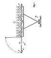
- 12 denotes the rear end of a tractor, to which a seed drill 11 is connected by means of a towing device.
- track markers 10 are connected to the side of the drill.
- Fig. 1 it is illustrated that an obstacle 13 has hit a laterally swung out marker, and due to the arrangement according to the invention, the marker 10 is not bent or broken, but pivoted into a position shown in dashed lines in Fig. 1. If, for example, the seeder 11 moves forward and thereby reaches the obstacle 13 shown in FIG. 1 by means of the track marker 10, then after the track marker 10 has been pivoted backwards and thus has passed the obstacle 13, pivot it back into its position shown in solid lines in FIG. 1.
- the track marker 10 consists of a support arm 14 which is provided at its outer end with a disc 15 which is rotatably mounted on the support arm 14.
- the support arm 14 has two hinge plates 20 which are rigidly connected, for example welded, to the support arm 14.
- the hinge plates 20 are equipped with mutually aligned bores, which serve to receive one hinge pin 22 each, on which hinge arms 21 are arranged to be horizontally pivotable.
- the individual hinge pins 22 are fixed by means of locking rings 23.
- the support arm 14 can be pivoted about the central axes of the articulation pins. If, for example, the track marker 10 is to be used, it can be pivoted downwards by means of a hydraulic cylinder 24.
- the hydraulic cylinder 24 is connected via a hinge pin 26 to a lever arm 25 which is connected to the hinge arm 21.
- the support arm 14 of the track marker 10 is to be raised, the piston rod of the associated hydraulic cylinder 24 is extended and the support arm 14 is thus raised into a position according to FIG. 1.
- the support arm 14 of the track marker 10 is located according to FIG. 1 with respect to the direction of travel on the right side of the seeder 11.
- the articulated arm 21 is in turn articulated to a frame 30 of the seed drill 11.
- the articulation device consists of two spaced-apart support plates 31, which are welded to the top and bottom of the frame 30, for example.
- the support plates are coaxial with one another mutually extending bores equipped to receive a vertically extending hinge pin 32.
- the hinge pin 32 also extends through the provided in the hinge arm 21 cylindrical bore, so that the hinge arm 21 and thus the support arm 14 of the marker 10 can pivot about a vertical axis extending through the hinge pin 32.
- the safety locking device includes a plate 35 which is rigidly connected to the frame 30 of the seed drill 11 and, for this purpose, is welded to the support plates 31 which are arranged at a distance from one another.
- the plate 35 has an opening 36 in the lower region through which a bushing 37 extends.
- the bush 37 has threads 38 over its entire length and a bore 39 at the end. Furthermore, the bush 37 is equipped at one end with a head whose diameter is larger than the diameter of the part of the bush which is provided with the thread 38 .
- the bore 39 extending through the bushing 37 serves to receive a screw bolt 43, which is also equipped with a screw head 44, only the front free end of the screw bolt having thread 45.
- a U-shaped bracket 50 is arranged on the hinge pin 22 and surrounds the hinge pin 22 (see FIGS. 3 and 4). Between the two exposed legs of the holder 50, a rectangular receiving part 51 is pivotally mounted, which is a right for this Has an angle to the hinge pin 22 extending bore in which a hinge pin 52 is received, which further extends through the holes provided in the legs of the bracket 50 and which is secured by means of snap rings 53 in the axial direction.
- the receiving part 51 has at its free end a rectangular recess 54 which is open towards the top of the holder 50 and one side of which is equipped with a U-shaped slot which is open towards the top.
- the depression 54 serves to receive the screw head 44, the slot adjoining the depression 54 serving to receive the screw bolt adjoining the screw head without a threaded part.
- a nut 55 can be screwed onto the thread 45 at the end of the screw bolt 43, so that the head 41 against the end face of the receiving part 51 is present and the bush 37 on the screw bolt 43 generates a pretension.
- the bolt 43 is biased slightly beyond the elastic area.
- the support arm 14 can pivot about the vertically extending joint bolt 32, so that the bush 37 passes through the opening 36 within the plate 35.
- the nut 42 is screwed onto the thread 38 of the bush 37 and tightened so far that pivoting about the axis of the pivot pin 32 is prevented. It is pointed out that when the track marker 10 strikes an obstacle 13, the forces which are necessary for pivoting the support arm 14 overcome the corresponding opposing forces and then pivot the support arm 14 into the position indicated by broken lines in FIG. 1.
- an actuating force acts, which is indicated by the arrow 60 in FIG. 2 indicates the bolt 43.
- the actuating force acts on a radius x which is defined by the distance between the axis of the pivot bolt 32 and the axis of the pivot bolt 52.
- the bolt 43 is arranged so that its axis is tangent to the circle drawn by the pivot bolt 52 (arrow 60). This prevents the bolt from being subjected to permanent deformation or bending beyond the elastic area.
- the screw bolt resists the normal tensile forces that act on the marker 10 when it is in use. Due to the advantageous arrangement of the individual parts, in particular the screw bolt, the shear forces acting on the screw bolt 43 are relatively low. However, if an obstacle strikes the support arm 14, the actuating forces applied by the screw bolt of the safety locking device are overcome, and the support arm 14 swivels backwards about the hinge pin 32, the screw bolt 43 being separated.
Landscapes
- Life Sciences & Earth Sciences (AREA)
- Soil Sciences (AREA)
- Environmental Sciences (AREA)
- Engineering & Computer Science (AREA)
- Mechanical Engineering (AREA)
- Guiding Agricultural Machines (AREA)
- Body Structure For Vehicles (AREA)
- Vehicle Cleaning, Maintenance, Repair, Refitting, And Outriggers (AREA)
Applications Claiming Priority (2)
| Application Number | Priority Date | Filing Date | Title |
|---|---|---|---|
| US59255484A | 1984-03-23 | 1984-03-23 | |
| US592554 | 1984-03-23 |
Publications (2)
| Publication Number | Publication Date |
|---|---|
| EP0155654A2 true EP0155654A2 (fr) | 1985-09-25 |
| EP0155654A3 EP0155654A3 (fr) | 1986-05-07 |
Family
ID=24371148
Family Applications (1)
| Application Number | Title | Priority Date | Filing Date |
|---|---|---|---|
| EP85103046A Withdrawn EP0155654A3 (fr) | 1984-03-23 | 1985-03-16 | Machine agricole |
Country Status (6)
| Country | Link |
|---|---|
| EP (1) | EP0155654A3 (fr) |
| AR (1) | AR246651A1 (fr) |
| AU (1) | AU3979285A (fr) |
| BR (1) | BR8501297A (fr) |
| ES (1) | ES8605349A1 (fr) |
| ZA (1) | ZA852185B (fr) |
Cited By (3)
| Publication number | Priority date | Publication date | Assignee | Title |
|---|---|---|---|---|
| FR2658979A1 (fr) * | 1990-03-02 | 1991-09-06 | Sulky Burel Sa | Dispositif de tracage pour machine agricole. |
| NL1000920C2 (nl) * | 1995-08-03 | 1997-02-04 | Maasland Nv | Zaaimachine. |
| WO2019046184A1 (fr) * | 2017-08-28 | 2019-03-07 | Harvest International, Inc. | Support de montage de machine agricole pour planter en rangs |
Families Citing this family (1)
| Publication number | Priority date | Publication date | Assignee | Title |
|---|---|---|---|---|
| US4530405A (en) * | 1984-03-23 | 1985-07-23 | Deere & Co. | Planter row marker |
Citations (5)
| Publication number | Priority date | Publication date | Assignee | Title |
|---|---|---|---|---|
| US1780112A (en) * | 1929-07-10 | 1930-10-28 | Firestone Tire & Rubber Co | Mill |
| US1947552A (en) * | 1933-06-12 | 1934-02-20 | Case Co J I | Mower |
| GB671797A (en) * | 1950-06-27 | 1952-05-07 | Int Harvester Co | Improvements in or relating to mowing or like machines |
| DE8104600U1 (de) * | 1981-02-19 | 1981-07-30 | Klöckner-Humboldt-Deutz AG Zweigniederlassung Fahr, 7702 Gottmadingen | "nachlaufeinrichtung an einem landwirtschaftlichen arbeitsgeraet" |
| WO1982002469A1 (fr) * | 1981-01-21 | 1982-08-05 | Bailey Alfred John | Semoir agricole |
Family Cites Families (1)
| Publication number | Priority date | Publication date | Assignee | Title |
|---|---|---|---|---|
| BE827201A (fr) * | 1975-03-26 | 1975-07-16 | Dispositif adaptable a un tracteur pour le tracage au sol de sillons delimitant des surfaces traitees avec des produits fertilisants |
-
1985
- 1985-03-11 AU AU39792/85A patent/AU3979285A/en not_active Abandoned
- 1985-03-16 EP EP85103046A patent/EP0155654A3/fr not_active Withdrawn
- 1985-03-21 AR AR85299832A patent/AR246651A1/es active
- 1985-03-22 ZA ZA852185A patent/ZA852185B/xx unknown
- 1985-03-22 ES ES541489A patent/ES8605349A1/es not_active Expired
- 1985-03-22 BR BR8501297A patent/BR8501297A/pt unknown
Patent Citations (5)
| Publication number | Priority date | Publication date | Assignee | Title |
|---|---|---|---|---|
| US1780112A (en) * | 1929-07-10 | 1930-10-28 | Firestone Tire & Rubber Co | Mill |
| US1947552A (en) * | 1933-06-12 | 1934-02-20 | Case Co J I | Mower |
| GB671797A (en) * | 1950-06-27 | 1952-05-07 | Int Harvester Co | Improvements in or relating to mowing or like machines |
| WO1982002469A1 (fr) * | 1981-01-21 | 1982-08-05 | Bailey Alfred John | Semoir agricole |
| DE8104600U1 (de) * | 1981-02-19 | 1981-07-30 | Klöckner-Humboldt-Deutz AG Zweigniederlassung Fahr, 7702 Gottmadingen | "nachlaufeinrichtung an einem landwirtschaftlichen arbeitsgeraet" |
Cited By (5)
| Publication number | Priority date | Publication date | Assignee | Title |
|---|---|---|---|---|
| FR2658979A1 (fr) * | 1990-03-02 | 1991-09-06 | Sulky Burel Sa | Dispositif de tracage pour machine agricole. |
| NL1000920C2 (nl) * | 1995-08-03 | 1997-02-04 | Maasland Nv | Zaaimachine. |
| EP0761082A1 (fr) * | 1995-08-03 | 1997-03-12 | Maasland N.V. | Semoir |
| WO2019046184A1 (fr) * | 2017-08-28 | 2019-03-07 | Harvest International, Inc. | Support de montage de machine agricole pour planter en rangs |
| US10512211B2 (en) | 2017-08-28 | 2019-12-24 | Harvest International, Inc. | Agricultural row planter mounting bracket |
Also Published As
| Publication number | Publication date |
|---|---|
| AU3979285A (en) | 1985-09-26 |
| ES8605349A1 (es) | 1986-03-16 |
| ZA852185B (en) | 1986-11-26 |
| AR246651A1 (es) | 1994-09-30 |
| EP0155654A3 (fr) | 1986-05-07 |
| ES541489A0 (es) | 1986-03-16 |
| BR8501297A (pt) | 1985-11-19 |
Similar Documents
| Publication | Publication Date | Title |
|---|---|---|
| EP0073359B1 (fr) | Dispositif de verrouillage pour faucheuse | |
| EP0924975B1 (fr) | Outil pour ameublir le sol en profondeur | |
| EP0533041B1 (fr) | Dispositif de guidage des bras d'attelage et véhicule agricole | |
| EP0792574A1 (fr) | Outil remorque | |
| DE10128101B4 (de) | Ährenheber | |
| DE3322551C2 (de) | Zwischenstück zum Ausschalten der Seitenbeweglichkeit von Unterlenkern eines Ackerschleppers | |
| EP0081742A1 (fr) | Appareil à travailler la terre déplaçable sur un champ | |
| DE3710167A1 (de) | Einstellbarer wegbegrenzer | |
| EP1167634B1 (fr) | Chassis de fixation pour des accessoires d'une machine de chantier et boulons de reception correspondants | |
| DE10149364A1 (de) | Mähmaschine | |
| EP0155654A2 (fr) | Machine agricole | |
| EP0426005A1 (fr) | Structure d'accouplement | |
| DE60319855T2 (de) | Rotierbare verbindung | |
| DE69708464T2 (de) | Landwirtschaftliche Maschine | |
| DE69613661T2 (de) | Schlepper aufgehängenes landwirtschaftliche Werkzeug mit einem Rahmen zür Verbindung mit der Dreipunktvorrichtung | |
| DE4242995C2 (de) | Kuppelvorrichtung zum Verbinden eines Traktors mit einem Gerät | |
| EP0567720B1 (fr) | Liaison à axe débrochable | |
| EP0072877B1 (fr) | Servomoteur de direction hydraulique | |
| DE102005032610B4 (de) | Blattfederaufhängung für Nutzfahrzeuge | |
| DE19810682C1 (de) | Überlastgesicherter Bodengrubber | |
| DE102021118849B3 (de) | Portalschneidwerk | |
| DE8905240U1 (de) | Mähmaschine | |
| EP0213579A2 (fr) | Machine agricole comportant un châssis et un cadre support d'outils | |
| DE102018132070B4 (de) | Anhängerkupplung | |
| DE69421165T2 (de) | Rohrpflugrahmenüberlastsicherung |
Legal Events
| Date | Code | Title | Description |
|---|---|---|---|
| PUAI | Public reference made under article 153(3) epc to a published international application that has entered the european phase |
Free format text: ORIGINAL CODE: 0009012 |
|
| AK | Designated contracting states |
Designated state(s): DE FR GB |
|
| PUAL | Search report despatched |
Free format text: ORIGINAL CODE: 0009013 |
|
| 17P | Request for examination filed |
Effective date: 19860306 |
|
| AK | Designated contracting states |
Kind code of ref document: A3 Designated state(s): DE FR GB |
|
| 17Q | First examination report despatched |
Effective date: 19871215 |
|
| STAA | Information on the status of an ep patent application or granted ep patent |
Free format text: STATUS: THE APPLICATION IS DEEMED TO BE WITHDRAWN |
|
| 18D | Application deemed to be withdrawn |
Effective date: 19871001 |
|
| RIN1 | Information on inventor provided before grant (corrected) |
Inventor name: STRINGFIELD WHITE, GREGORY Inventor name: ERICKSON, WILLIAM EUGENE |