US4530405A - Planter row marker - Google Patents
Planter row marker Download PDFInfo
- Publication number
- US4530405A US4530405A US06/592,521 US59252184A US4530405A US 4530405 A US4530405 A US 4530405A US 59252184 A US59252184 A US 59252184A US 4530405 A US4530405 A US 4530405A
- Authority
- US
- United States
- Prior art keywords
- marker
- row
- working position
- frame
- slot
- Prior art date
- Legal status (The legal status is an assumption and is not a legal conclusion. Google has not performed a legal analysis and makes no representation as to the accuracy of the status listed.)
- Expired - Lifetime
Links
- 239000003550 marker Substances 0.000 title claims abstract description 46
- 230000003213 activating effect Effects 0.000 abstract description 2
- 230000004913 activation Effects 0.000 description 2
- 239000002689 soil Substances 0.000 description 2
- 238000013459 approach Methods 0.000 description 1
- 230000000694 effects Effects 0.000 description 1
- 238000000034 method Methods 0.000 description 1
- 238000012986 modification Methods 0.000 description 1
- 230000004048 modification Effects 0.000 description 1
Images

Classifications
-
- A—HUMAN NECESSITIES
- A01—AGRICULTURE; FORESTRY; ANIMAL HUSBANDRY; HUNTING; TRAPPING; FISHING
- A01B—SOIL WORKING IN AGRICULTURE OR FORESTRY; PARTS, DETAILS, OR ACCESSORIES OF AGRICULTURAL MACHINES OR IMPLEMENTS, IN GENERAL
- A01B69/00—Steering of agricultural machines or implements; Guiding agricultural machines or implements on a desired track
- A01B69/02—Ridge-marking or like devices; Checkrow wires; Accessories therefor
- A01B69/024—Ridge-marking or like devices; Checkrow wires; Accessories therefor adapted to cut and form a ridge or forrow in the soil surface, e.g. with a disc
Definitions
- This invention relates to row markers for planting implements, and more particularly to row markers that move or float with the contour of the ground.
- Planter row markers that float with the contour of the ground provide a continuous visible marking that aids the operator in the planting process.
- Presently known floating row markers use a straight slotted engagement of the activating hydraulic cylinder end pin. While the straight slot does allow for floating of the marker with the ground contour, its use also results in an undesirable jump or free fall of the marker as the marker initially moves from the vertical position.
- presently known floating row markers using a cable connection present special problems. If the cable is adjusted so the marker will completely unfold above the ground, the cable will be too short to allow the marker to go to its normal working position. If the cable is adjusted to the full range of floatation, the marker disk will contact the ground before the marker is completely unfolded resulting in the disk ends pushing soil to unfold into the ground possibly resulting in structural damage.
- the present invention provides a planter row marker having a floatation slot in the link arm connected to the actuating hydraulic cylinder.
- the slot has a hooked portion in the outer end which quickly engages the end pin of the cylinder as it is retracted. This rapid engagement eliminates the jump or free fall associated with known floatation slots.
- the row marker of the present invention also employs a spring tensioned cable to fully extend the outer link arm before the marker descends to its normal working position where the marker disk contacts the soil.
- the tension spring allows use of a short cable to effect full extension before reaching the working position, while at the same time providing the extra stretched length needed to assure a clear marking throughout the full floatation range allowed by the slot.
- An object of the present invention is the provision of an improved planter row marker.
- Another object is to provide a planter row marker that floats with the contour of the ground.
- a further object of the invention is the provision of planter row markers that unfold in a smooth even manner.
- Still another object is to provide a planter row marker that fully extends before reaching the normal working position.
- a still further object of the present invention is the provision of planter row markers that produce a clear visible marking.
- FIG. 1 is a perspective view showing row markers attached to opposite ends of a frame, and showing, in dashed lines, a plurality of planter units attached to the main frame;
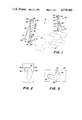
- FIG. 2 is a cut-away front elevational view of a portion of the inner link of a foldable marker arm when the inner link and marker are in the raised vertical position, the view showing a substantially longitudinal slot with a transverse hook at the outer end and the position of the hydraulic cylinder end pin within the hooked portion;
- FIG. 3 is a cut-away front elevational view of a portion of the inner link of a foldable marker arm similar to FIG. 2 but where the inner link and marker are in the lowered horizontal working position, the view showing the range of travel of the hydraulic cylinder end pin within the slot formed in the inner link;
- FIG. 4 is a front elevational view showing the row marker in the raised position, a horizontal completely unfolded position (dashed lines), and the normal working position (dashed lines).
- FIG. 1 shows a planting implement (10) including a frame (12) having a plurality of planting units (14) attached thereto.
- Each end of the frame (12) carries a row marker (20) pivotally attached by a horizontal pin (22).
- the row markers (20) include an inner link arm (24) and an outer link arm (26) pivotally attached by pin (28).
- the marker disk blade (30) is mounted on an arm tube (31) which is conventionally adjustable with respect to outer link (26) to properly position the marker disk (30) for use in conjunction with various row width settings.
- a hydraulic cylinder (32) is pivotally connected by pin (34) to the frame (12) and by cylinder end pin (36) to the slot (40) in inner link arm (24). Selective activation of the cylinder (32) moves the row marker (20) between the vertical raised position and the lowered working position as generally shown in FIG. 4.
- the outer link arm (26) is extended laterally from the frame (12) as the cylinder (32) moves the row marker (20) toward the lowered working position.
- the cable (50) and attached tension spring (52) is connected between a frame offset strap (54) and a pin offset strap (56).
- Pin offset strap (56) is, in turn, pivotally attached to the lever plate (58) that extends up from one end of the outer link arm (26). As the row marker (20) is lowered the force exerted on the lever plate (58) acts to pivot the outer link arm (26) about pin (28) until it reaches a stop (not shown) at the fully extended horizontal position shown in FIG. 4.
- the configuration of the slot (40) of the inner link arm (24) is important to the smooth efficient operation of the row marker (20).
- the slot (40) is disposed generally longitudinally to the inner link (24) but the slot (40) also has a generally transverse hooked portion (42) at the outer end (FIGS. 2 and 3).
- the hydraulic cylinder (32) is activated to retract and move the cylinder end pin (36) downward in the hooked portion (42) of the slot (40) as shown best in FIG. 2.
- the end pin (36) When the end pin (36) is in the dashed line position of FIG. 2, it exerts a force on the inner link arm (24) and it begins to pivot about pin (22) toward the desired working position in a smooth even descent.
- the end pin (36) As the row marker (20) approaches the working position, the end pin (36) is no longer restricted by the hook portion (42) and is free to travel within the slot (40) as illustrated in FIG. 3.
- the tension spring (52) attached to the cable (50) also contributes to the efficient operation of the row marker (20) by providing for full extension of the outer link arm (26) before the disk (30) contacts the ground. This full extension is accomplished when the row marker reaches the horizontal position shown in dashed lines in FIG. 4, at which point the spring (52) is not stretched.
- the spring (52) begins to stretch when the row marker (20) reaches the normal working position illustrated by the lowermost dashed line representation in FIG. 4.
- the spring (52) also stretches when the disk (30) floats below the normal working position as it follows the contour of the land.
- the row marker (20) is raised by activation to extend the hydraulic cylinder (32) which causes the inner link arm (24) to pivot about pin (22) in an upward direction.
- hooked slot insures a smooth folding row marker that overcomes the problem of jumpy, uneven operation. Also, use of the spring tensioned cable provides for full extension of the marker and extra length that allows clear marking throughout the full floatation range of the slot.
Landscapes
- Life Sciences & Earth Sciences (AREA)
- Engineering & Computer Science (AREA)
- Mechanical Engineering (AREA)
- Soil Sciences (AREA)
- Environmental Sciences (AREA)
- Guiding Agricultural Machines (AREA)
- Transplanting Machines (AREA)
Abstract
A row marker for a planting implement having a floatation slot formed in an extendable marker link arm. The link arm slot is generally longitudinal to the link arm and has a transverse hooked portion at the outer end. Engagement of the end pin of an activating hydraulic cylinder in the hook portion results in a smooth even motion of the marker as it moves from the vertical position to the normal working position. Use of a spring tensioned cable simultaneously provides for full marker arm extension prior to reaching the working position and clear marking through the full range of floatation.
Description
This invention relates to row markers for planting implements, and more particularly to row markers that move or float with the contour of the ground.
Planter row markers that float with the contour of the ground provide a continuous visible marking that aids the operator in the planting process. Presently known floating row markers use a straight slotted engagement of the activating hydraulic cylinder end pin. While the straight slot does allow for floating of the marker with the ground contour, its use also results in an undesirable jump or free fall of the marker as the marker initially moves from the vertical position. Also, presently known floating row markers using a cable connection present special problems. If the cable is adjusted so the marker will completely unfold above the ground, the cable will be too short to allow the marker to go to its normal working position. If the cable is adjusted to the full range of floatation, the marker disk will contact the ground before the marker is completely unfolded resulting in the disk ends pushing soil to unfold into the ground possibly resulting in structural damage.
Those concerned with these and other problems recognize the need for an improved planter row marker.
The present invention provides a planter row marker having a floatation slot in the link arm connected to the actuating hydraulic cylinder. The slot has a hooked portion in the outer end which quickly engages the end pin of the cylinder as it is retracted. This rapid engagement eliminates the jump or free fall associated with known floatation slots.
The row marker of the present invention also employs a spring tensioned cable to fully extend the outer link arm before the marker descends to its normal working position where the marker disk contacts the soil. The tension spring allows use of a short cable to effect full extension before reaching the working position, while at the same time providing the extra stretched length needed to assure a clear marking throughout the full floatation range allowed by the slot.
An object of the present invention is the provision of an improved planter row marker.
Another object is to provide a planter row marker that floats with the contour of the ground.
A further object of the invention is the provision of planter row markers that unfold in a smooth even manner.
Still another object is to provide a planter row marker that fully extends before reaching the normal working position.
A still further object of the present invention is the provision of planter row markers that produce a clear visible marking.
These and other attributes of the invention will become more clear upon a thorough study of the following description of the best mode for carrying out the invention, particularly when reviewed in conjunction with the drawings, wherein:
FIG. 1 is a perspective view showing row markers attached to opposite ends of a frame, and showing, in dashed lines, a plurality of planter units attached to the main frame;
FIG. 2 is a cut-away front elevational view of a portion of the inner link of a foldable marker arm when the inner link and marker are in the raised vertical position, the view showing a substantially longitudinal slot with a transverse hook at the outer end and the position of the hydraulic cylinder end pin within the hooked portion;
FIG. 3 is a cut-away front elevational view of a portion of the inner link of a foldable marker arm similar to FIG. 2 but where the inner link and marker are in the lowered horizontal working position, the view showing the range of travel of the hydraulic cylinder end pin within the slot formed in the inner link; and
FIG. 4 is a front elevational view showing the row marker in the raised position, a horizontal completely unfolded position (dashed lines), and the normal working position (dashed lines).
Referring now to the drawings, wherein like reference numerals designate identical or corresponding parts throughout the several views, FIG. 1 shows a planting implement (10) including a frame (12) having a plurality of planting units (14) attached thereto. Each end of the frame (12) carries a row marker (20) pivotally attached by a horizontal pin (22). The row markers (20) include an inner link arm (24) and an outer link arm (26) pivotally attached by pin (28). The marker disk blade (30) is mounted on an arm tube (31) which is conventionally adjustable with respect to outer link (26) to properly position the marker disk (30) for use in conjunction with various row width settings.
A hydraulic cylinder (32) is pivotally connected by pin (34) to the frame (12) and by cylinder end pin (36) to the slot (40) in inner link arm (24). Selective activation of the cylinder (32) moves the row marker (20) between the vertical raised position and the lowered working position as generally shown in FIG. 4.
The outer link arm (26) is extended laterally from the frame (12) as the cylinder (32) moves the row marker (20) toward the lowered working position. The cable (50) and attached tension spring (52) is connected between a frame offset strap (54) and a pin offset strap (56). Pin offset strap (56) is, in turn, pivotally attached to the lever plate (58) that extends up from one end of the outer link arm (26). As the row marker (20) is lowered the force exerted on the lever plate (58) acts to pivot the outer link arm (26) about pin (28) until it reaches a stop (not shown) at the fully extended horizontal position shown in FIG. 4.
The configuration of the slot (40) of the inner link arm (24) is important to the smooth efficient operation of the row marker (20). The slot (40) is disposed generally longitudinally to the inner link (24) but the slot (40) also has a generally transverse hooked portion (42) at the outer end (FIGS. 2 and 3).
In operation, when it is desired to move the row marker (20) from the vertical raised position, the hydraulic cylinder (32) is activated to retract and move the cylinder end pin (36) downward in the hooked portion (42) of the slot (40) as shown best in FIG. 2. When the end pin (36) is in the dashed line position of FIG. 2, it exerts a force on the inner link arm (24) and it begins to pivot about pin (22) toward the desired working position in a smooth even descent. As the row marker (20) approaches the working position, the end pin (36) is no longer restricted by the hook portion (42) and is free to travel within the slot (40) as illustrated in FIG. 3.
The tension spring (52) attached to the cable (50) also contributes to the efficient operation of the row marker (20) by providing for full extension of the outer link arm (26) before the disk (30) contacts the ground. This full extension is accomplished when the row marker reaches the horizontal position shown in dashed lines in FIG. 4, at which point the spring (52) is not stretched. The spring (52) begins to stretch when the row marker (20) reaches the normal working position illustrated by the lowermost dashed line representation in FIG. 4. The spring (52) also stretches when the disk (30) floats below the normal working position as it follows the contour of the land.
The row marker (20) is raised by activation to extend the hydraulic cylinder (32) which causes the inner link arm (24) to pivot about pin (22) in an upward direction.
It can be understood that the hooked slot insures a smooth folding row marker that overcomes the problem of jumpy, uneven operation. Also, use of the spring tensioned cable provides for full extension of the marker and extra length that allows clear marking throughout the full floatation range of the slot.
Thus, it can be seen that at least all of the stated objectives have been achieved.
Obviously, many modifications and variations of the present invention are possible in light of the above teachings. It is therefore to be understood that, within the scope of the appended claims, the invention may be practiced otherwise than as specifically described.
Claims (2)
1. In a row marker for use in conjunction with a planting implement including a plurality of planting units attached to a frame, a foldable support arm attached to the frame, a marker disk blade attached to the end of the vertically foldable support arm, a hydraulic cylinder interconnecting the frame and an inner link of the foldable support arm for selectively moving the row marker between a raised position and a lowered working position, and a cable interconnecting the frame and an outer link of the foldable support arm for selectively extending the outer link when the row marker moves toward its lowered working position, the improvement comprising:
an inner link arm having a slot to receive an end pin carried by the hydraulic cylinder, said slot being disposed to slideably receive said end pin and being defined by a path generally longitudinal to the inner link and having a generally transverse hooked portion at the outer end thereof.
2. The row marker of claim 1, further including a tension spring attached to said cable and disposed between said frame and said outer link, whereby the outer link is fully extended before the said row marker reaches said lowered working position.
Priority Applications (10)
| Application Number | Priority Date | Filing Date | Title |
|---|---|---|---|
| US06/592,521 US4530405A (en) | 1984-03-23 | 1984-03-23 | Planter row marker |
| CA000473902A CA1247459A (en) | 1984-03-23 | 1985-02-08 | Planter row marker |
| AU39787/85A AU574444B2 (en) | 1984-03-23 | 1985-03-11 | Planter row marker |
| EP85102847A EP0155631B1 (en) | 1984-03-23 | 1985-03-13 | Ridge marker for an agricultural implement |
| DE8585102847T DE3571737D1 (en) | 1984-03-23 | 1985-03-13 | Ridge marker for an agricultural implement |
| AR85299833A AR246652A1 (en) | 1984-03-23 | 1985-03-21 | Ridge marker for an agricultural implement |
| ZA852182A ZA852182B (en) | 1984-03-23 | 1985-03-22 | Planter row marker |
| ES541490A ES8605350A1 (en) | 1984-03-23 | 1985-03-22 | Ridge marker for an agricultural implement. |
| MX204696A MX166295B (en) | 1984-03-23 | 1985-03-22 | IMPROVEMENTS TO LINE MARKER FOR CULTIVATION |
| BR8501294A BR8501294A (en) | 1984-03-23 | 1985-03-22 | ROW MARKER FOR EMPLOYMENT WITH A PLANTING IMPLEMENT |
Applications Claiming Priority (1)
| Application Number | Priority Date | Filing Date | Title |
|---|---|---|---|
| US06/592,521 US4530405A (en) | 1984-03-23 | 1984-03-23 | Planter row marker |
Publications (1)
| Publication Number | Publication Date |
|---|---|
| US4530405A true US4530405A (en) | 1985-07-23 |
Family
ID=24371015
Family Applications (1)
| Application Number | Title | Priority Date | Filing Date |
|---|---|---|---|
| US06/592,521 Expired - Lifetime US4530405A (en) | 1984-03-23 | 1984-03-23 | Planter row marker |
Country Status (10)
| Country | Link |
|---|---|
| US (1) | US4530405A (en) |
| EP (1) | EP0155631B1 (en) |
| AR (1) | AR246652A1 (en) |
| AU (1) | AU574444B2 (en) |
| BR (1) | BR8501294A (en) |
| CA (1) | CA1247459A (en) |
| DE (1) | DE3571737D1 (en) |
| ES (1) | ES8605350A1 (en) |
| MX (1) | MX166295B (en) |
| ZA (1) | ZA852182B (en) |
Cited By (59)
| Publication number | Priority date | Publication date | Assignee | Title |
|---|---|---|---|---|
| EP0176084A3 (en) * | 1984-09-25 | 1987-02-04 | Amazonen-Werke H. Dreyer Gmbh & Co. Kg | Apparatus for distributing granular material |
| US4674578A (en) * | 1986-01-09 | 1987-06-23 | J. I. Case Company | Floating marker arm mechanism |
| US5027525A (en) * | 1989-10-02 | 1991-07-02 | Duane Haukaas | Field marker |
| US5379847A (en) * | 1993-08-24 | 1995-01-10 | Deere & Company | Tri-fold row marker |
| US5408756A (en) * | 1993-11-09 | 1995-04-25 | Orthman Manufacturing, Inc. | Bifold field marker |
| US5425427A (en) * | 1994-01-13 | 1995-06-20 | Poma Industries, Inc. | Folding marker for agricultural implement |
| US5485796A (en) * | 1994-03-22 | 1996-01-23 | Dawn Equipment Company | Apparatus for marking soil |
| US5542190A (en) * | 1993-11-09 | 1996-08-06 | Orthman Manufacturing, Inc. | Bifold field marker |
| EP0761082A1 (en) * | 1995-08-03 | 1997-03-12 | Maasland N.V. | A drilling machine |
| US20090020298A1 (en) * | 2007-07-18 | 2009-01-22 | Harnetiaux Travis L | Method And Apparatus For A Folding Marker For An Agricultural Implement |
| US7743843B1 (en) | 2009-02-10 | 2010-06-29 | Cnh Canada, Ltd. | Marker assembly for an agricultural implement |
| US7743842B1 (en) | 2009-02-10 | 2010-06-29 | Cnh Canada, Ltd. | Marker assembly having float feature |
| US20100200253A1 (en) * | 2009-02-10 | 2010-08-12 | Friggstad Terrance A | Marker Assembly Having Caster Wheel |
| US20100200256A1 (en) * | 2009-02-10 | 2010-08-12 | Gerry Gadzella | Marker Assembly Having Spring Linkage To Limit Momentum In Marker Assembly During Marker Assembly Deployment |
| US20100200254A1 (en) * | 2009-02-10 | 2010-08-12 | Naylor Matthew S | Marker Assembly Having Rigid Link And Cam Assembly |
| US8016043B2 (en) | 2009-02-10 | 2011-09-13 | Cnh Canada, Ltd. | Marker assembly having breakaway feature |
| US8327780B2 (en) | 2009-10-16 | 2012-12-11 | Dawn Equipment Company | Agricultural implement having fluid delivery features |
| US8359988B2 (en) | 2007-07-24 | 2013-01-29 | Dawn Equipment Company | Agricultural tillage device |
| US8544398B2 (en) | 2010-09-15 | 2013-10-01 | Dawn Equipment Company | Hydraulic down pressure control system for closing wheels of an agricultural implement |
| US8544397B2 (en) | 2010-09-15 | 2013-10-01 | Dawn Equipment Company | Row unit for agricultural implement |
| US8636077B2 (en) | 2012-05-22 | 2014-01-28 | Dawn Equipment Company | Agricultural tool with structural housing for hydraulic actuator |
| US8763713B2 (en) | 2012-01-27 | 2014-07-01 | Dawn Equipment Company | Agricultural implement with automatic down pressure control |
| US8776702B2 (en) | 2010-09-15 | 2014-07-15 | Dawn Equipment Company | Hydraulic down pressure control system for an agricultural implement |
| USRE45091E1 (en) | 2008-12-01 | 2014-08-26 | Dawn Equipment Company | Row-clearing unit for agricultural implement |
| US8863857B2 (en) | 2011-02-23 | 2014-10-21 | Dawn Equipment Company | Row unit for agricultural implement |
| US8910581B2 (en) | 2012-07-25 | 2014-12-16 | Dawn Equipment Company | Side dressing fertilizer coulter |
| US8985232B2 (en) | 2012-08-20 | 2015-03-24 | Dawn Equipment Company | Agricultural apparatus for sensing and providing feedback of soil property changes in real time |
| US9055712B2 (en) | 2010-09-15 | 2015-06-16 | Dawn Equipment Company | Agricultural apparatus with integrated controller for a row unit |
| US9107338B2 (en) | 2010-09-15 | 2015-08-18 | Dawn Equipment Company | Agricultural systems |
| US9107337B2 (en) | 2012-08-20 | 2015-08-18 | Dawn Equipment Company | Agricultural apparatus for sensing and providing feedback of soil property changes in real time |
| US9144189B2 (en) | 2012-07-25 | 2015-09-29 | Precision Planting Llc | Integrated implement downforce control systems, methods, and apparatus |
| US9192091B2 (en) | 2013-02-01 | 2015-11-24 | Dawn Equipment Company | Agricultural apparatus with hybrid single-disk, double-disk coulter arrangement |
| US9215838B2 (en) | 2013-02-01 | 2015-12-22 | Dawn Equipment Company | Agricultural apparatus with hybrid single-disk, double-disk coulter arrangement |
| US9226440B2 (en) | 2010-09-15 | 2016-01-05 | Dawn Equipment Company | Agricultural apparatus with hydraulic cylinder and manifold for a row unit |
| US9232687B2 (en) | 2010-09-15 | 2016-01-12 | Dawn Equipment Company | Agricultural systems |
| US9241438B2 (en) | 2014-02-05 | 2016-01-26 | Dawn Equipment Company | Agricultural system for field preparation |
| US9271437B2 (en) | 2011-07-01 | 2016-03-01 | Charles H. Martin | Agricultural field preparation device |
| US9288937B2 (en) | 2011-08-05 | 2016-03-22 | Precision Planting Llc | Apparatus, systems and methods for row unit downforce control |
| EP3106010A1 (en) * | 2015-06-16 | 2016-12-21 | Amazonen-Werke H. Dreyer GmbH & Co. KG | Seeding device |
| US9615497B2 (en) | 2014-02-21 | 2017-04-11 | Dawn Equipment Company | Modular autonomous farm vehicle |
| US9668398B2 (en) | 2014-02-05 | 2017-06-06 | Dawn Equipment Company | Agricultural system for field preparation |
| US9723778B2 (en) | 2014-11-07 | 2017-08-08 | Dawn Equipment Company | Agricultural system |
| US9848522B2 (en) | 2014-11-07 | 2017-12-26 | Dawn Equipment Company | Agricultural system |
| US20180220576A1 (en) * | 2015-10-01 | 2018-08-09 | Kinze Manufacturing, Inc. | Wing flex apparatus for agricultural planter |
| US10444774B2 (en) | 2014-11-07 | 2019-10-15 | Dawn Equipment Company | Agricultural system |
| US10477760B2 (en) | 2015-12-28 | 2019-11-19 | Underground Agriculture, LLC | Agricultural organic device for weed control |
| US20190387656A1 (en) * | 2018-06-26 | 2019-12-26 | Cnh Industrial America Llc | Marker arm spring retainer |
| US10548260B2 (en) | 2017-05-04 | 2020-02-04 | Dawn Equipment Company | System for automatically setting the set point of a planter automatic down pressure control system with a seed furrow sidewall compaction measurement device |
| US10582653B2 (en) | 2014-11-07 | 2020-03-10 | Dawn Equipment Company | Agricultural planting system with automatic depth control |
| US10645865B2 (en) | 2017-05-04 | 2020-05-12 | Dawn Equipment Company | Agricultural row unit with automatic control system for furrow closing device |
| US10721855B2 (en) | 2014-02-05 | 2020-07-28 | Dawn Equipment Company | Agricultural system for field preparation |
| US10980174B2 (en) | 2015-12-28 | 2021-04-20 | Underground Agriculture, LLC | Agricultural mowing device |
| US11006563B2 (en) | 2017-05-04 | 2021-05-18 | Dawn Equipment Company | Seed firming device for improving seed to soil contact in a planter furrow with feature designed to prevent the buildup of soil on the outer surfaces by discharging pressurized fluid |
| US11083134B2 (en) | 2015-12-28 | 2021-08-10 | Underground Agriculture, LLC | Agricultural inter-row mowing device |
| US11197411B2 (en) | 2014-11-07 | 2021-12-14 | Dawn Equipment Company | Agricultural planting system with automatic depth control |
| US12016257B2 (en) | 2020-02-19 | 2024-06-25 | Sabanto, Inc. | Methods for detecting and clearing debris from planter gauge wheels, closing wheels and seed tubes |
| US12171152B2 (en) | 2010-09-15 | 2024-12-24 | Deere & Company | System and method for adaptively controlling depth of ground-engaging planting row unit using forward sensor that measures residue ahead of row unit |
| US12389816B2 (en) | 2013-02-04 | 2025-08-19 | Deere & Company | Agricultural systems |
| US12461083B2 (en) | 2020-08-03 | 2025-11-04 | Sabanto, Inc. | Methods for improved agricultural procedures |
Citations (10)
| Publication number | Priority date | Publication date | Assignee | Title |
|---|---|---|---|---|
| US895507A (en) * | 1908-04-13 | 1908-08-11 | Oliver Smith | Marking attachment for corn-planters. |
| US3072200A (en) * | 1960-04-04 | 1963-01-08 | Allis Chalmers Mfg Co | Row marker |
| US3650333A (en) * | 1970-09-14 | 1972-03-21 | Int Harvester Co | Hinge mechanism for folding disk harrow gangs |
| US3666019A (en) * | 1969-10-07 | 1972-05-30 | Case Co J I | Row marking apparatus |
| DE2216014A1 (en) * | 1972-04-01 | 1973-10-11 | Troester A J Fa | DEVICE FOR ALTERNATIVE ACTIVATION OF LEAVERS |
| US3766987A (en) * | 1972-01-24 | 1973-10-23 | Orthman Manufacturing | Planter marker |
| US4047575A (en) * | 1976-01-08 | 1977-09-13 | Allis-Chalmers Corporation | Foldup implement with lift arrangement for wing thereof |
| US4074766A (en) * | 1976-05-24 | 1978-02-21 | Orthman Manufacturing Inc. | Floating folding tool bar having a lock means |
| US4207950A (en) * | 1978-04-27 | 1980-06-17 | Kinzenbaw Jon E | Agricultural row marker |
| US4232747A (en) * | 1978-08-03 | 1980-11-11 | Krause Plow Corporation | Farm implement and control structure for wing sections thereof |
Family Cites Families (3)
| Publication number | Priority date | Publication date | Assignee | Title |
|---|---|---|---|---|
| US3828860A (en) * | 1973-02-28 | 1974-08-13 | Kewanne Machinery & Conveyor C | Agricultural implement with foldable wings |
| FR2457062A1 (en) * | 1979-05-21 | 1980-12-19 | Decommer Pierre | Boom for agricultural spraying - has both sides fitted with tracer wheels and is extended and raised by single acting hydraulic cylinder |
| AU3979285A (en) * | 1984-03-23 | 1985-09-26 | Deere & Company | Breakaway mechanism for a row marker |
-
1984
- 1984-03-23 US US06/592,521 patent/US4530405A/en not_active Expired - Lifetime
-
1985
- 1985-02-08 CA CA000473902A patent/CA1247459A/en not_active Expired
- 1985-03-11 AU AU39787/85A patent/AU574444B2/en not_active Ceased
- 1985-03-13 DE DE8585102847T patent/DE3571737D1/en not_active Expired
- 1985-03-13 EP EP85102847A patent/EP0155631B1/en not_active Expired
- 1985-03-21 AR AR85299833A patent/AR246652A1/en active
- 1985-03-22 BR BR8501294A patent/BR8501294A/en not_active IP Right Cessation
- 1985-03-22 ZA ZA852182A patent/ZA852182B/en unknown
- 1985-03-22 MX MX204696A patent/MX166295B/en unknown
- 1985-03-22 ES ES541490A patent/ES8605350A1/en not_active Expired
Patent Citations (10)
| Publication number | Priority date | Publication date | Assignee | Title |
|---|---|---|---|---|
| US895507A (en) * | 1908-04-13 | 1908-08-11 | Oliver Smith | Marking attachment for corn-planters. |
| US3072200A (en) * | 1960-04-04 | 1963-01-08 | Allis Chalmers Mfg Co | Row marker |
| US3666019A (en) * | 1969-10-07 | 1972-05-30 | Case Co J I | Row marking apparatus |
| US3650333A (en) * | 1970-09-14 | 1972-03-21 | Int Harvester Co | Hinge mechanism for folding disk harrow gangs |
| US3766987A (en) * | 1972-01-24 | 1973-10-23 | Orthman Manufacturing | Planter marker |
| DE2216014A1 (en) * | 1972-04-01 | 1973-10-11 | Troester A J Fa | DEVICE FOR ALTERNATIVE ACTIVATION OF LEAVERS |
| US4047575A (en) * | 1976-01-08 | 1977-09-13 | Allis-Chalmers Corporation | Foldup implement with lift arrangement for wing thereof |
| US4074766A (en) * | 1976-05-24 | 1978-02-21 | Orthman Manufacturing Inc. | Floating folding tool bar having a lock means |
| US4207950A (en) * | 1978-04-27 | 1980-06-17 | Kinzenbaw Jon E | Agricultural row marker |
| US4232747A (en) * | 1978-08-03 | 1980-11-11 | Krause Plow Corporation | Farm implement and control structure for wing sections thereof |
Non-Patent Citations (2)
| Title |
|---|
| Avco New Idea, Single Frame Planters, Form No. 8330 1, undated. * |
| Avco New Idea, Single Frame Planters, Form No. 8330-1, undated. |
Cited By (91)
| Publication number | Priority date | Publication date | Assignee | Title |
|---|---|---|---|---|
| EP0176084A3 (en) * | 1984-09-25 | 1987-02-04 | Amazonen-Werke H. Dreyer Gmbh & Co. Kg | Apparatus for distributing granular material |
| US4674578A (en) * | 1986-01-09 | 1987-06-23 | J. I. Case Company | Floating marker arm mechanism |
| US5027525A (en) * | 1989-10-02 | 1991-07-02 | Duane Haukaas | Field marker |
| US5379847A (en) * | 1993-08-24 | 1995-01-10 | Deere & Company | Tri-fold row marker |
| US5408756A (en) * | 1993-11-09 | 1995-04-25 | Orthman Manufacturing, Inc. | Bifold field marker |
| US5542190A (en) * | 1993-11-09 | 1996-08-06 | Orthman Manufacturing, Inc. | Bifold field marker |
| US5425427A (en) * | 1994-01-13 | 1995-06-20 | Poma Industries, Inc. | Folding marker for agricultural implement |
| US5485796A (en) * | 1994-03-22 | 1996-01-23 | Dawn Equipment Company | Apparatus for marking soil |
| EP0761082A1 (en) * | 1995-08-03 | 1997-03-12 | Maasland N.V. | A drilling machine |
| US7644780B2 (en) * | 2007-07-18 | 2010-01-12 | Cnh America, Llc. | Method and apparatus for a folding marker for an agricultural implement |
| US20090020298A1 (en) * | 2007-07-18 | 2009-01-22 | Harnetiaux Travis L | Method And Apparatus For A Folding Marker For An Agricultural Implement |
| US8359988B2 (en) | 2007-07-24 | 2013-01-29 | Dawn Equipment Company | Agricultural tillage device |
| USRE45091E1 (en) | 2008-12-01 | 2014-08-26 | Dawn Equipment Company | Row-clearing unit for agricultural implement |
| US7854271B2 (en) | 2009-02-10 | 2010-12-21 | Cnh Canada, Ltd. | Marker assembly having rigid link and cam assembly |
| US20100200256A1 (en) * | 2009-02-10 | 2010-08-12 | Gerry Gadzella | Marker Assembly Having Spring Linkage To Limit Momentum In Marker Assembly During Marker Assembly Deployment |
| US20100200254A1 (en) * | 2009-02-10 | 2010-08-12 | Naylor Matthew S | Marker Assembly Having Rigid Link And Cam Assembly |
| US20100200253A1 (en) * | 2009-02-10 | 2010-08-12 | Friggstad Terrance A | Marker Assembly Having Caster Wheel |
| US7984767B2 (en) | 2009-02-10 | 2011-07-26 | Cnh Canada, Ltd. | Marker assembly having caster wheel |
| US8011439B2 (en) | 2009-02-10 | 2011-09-06 | Cnh Canada, Ltd. | Marker assembly having spring linkage to limit momentum in marker assembly during marker assembly deployment |
| US8016043B2 (en) | 2009-02-10 | 2011-09-13 | Cnh Canada, Ltd. | Marker assembly having breakaway feature |
| US7743842B1 (en) | 2009-02-10 | 2010-06-29 | Cnh Canada, Ltd. | Marker assembly having float feature |
| US7743843B1 (en) | 2009-02-10 | 2010-06-29 | Cnh Canada, Ltd. | Marker assembly for an agricultural implement |
| US8327780B2 (en) | 2009-10-16 | 2012-12-11 | Dawn Equipment Company | Agricultural implement having fluid delivery features |
| US9232687B2 (en) | 2010-09-15 | 2016-01-12 | Dawn Equipment Company | Agricultural systems |
| US9788472B2 (en) | 2010-09-15 | 2017-10-17 | Dawn Equipment Company | Row unit for agricultural implement |
| US10506755B2 (en) | 2010-09-15 | 2019-12-17 | Dawn Equipment Company | Agricultural systems |
| US8770308B2 (en) | 2010-09-15 | 2014-07-08 | Dawn Equipment Company | Row unit for agricultural implement |
| US8776702B2 (en) | 2010-09-15 | 2014-07-15 | Dawn Equipment Company | Hydraulic down pressure control system for an agricultural implement |
| US8544397B2 (en) | 2010-09-15 | 2013-10-01 | Dawn Equipment Company | Row unit for agricultural implement |
| US10238024B2 (en) | 2010-09-15 | 2019-03-26 | Dawn Equipment Company | Row unit for agricultural implement |
| US11122726B2 (en) | 2010-09-15 | 2021-09-21 | Dawn Equipment Company | Agricultural systems |
| US10477752B2 (en) | 2010-09-15 | 2019-11-19 | Dawn Equipment Company | Row unit for agricultural implement |
| US9055712B2 (en) | 2010-09-15 | 2015-06-16 | Dawn Equipment Company | Agricultural apparatus with integrated controller for a row unit |
| US9107338B2 (en) | 2010-09-15 | 2015-08-18 | Dawn Equipment Company | Agricultural systems |
| US11470754B2 (en) | 2010-09-15 | 2022-10-18 | Dawn Equipment Company | Agricultural systems |
| US12150399B2 (en) | 2010-09-15 | 2024-11-26 | Deere & Company | Row unit for agricultural implement |
| US9144187B2 (en) | 2010-09-15 | 2015-09-29 | Dawn Equipment Company | Agricultural apparatus with hydraulic cylinder and manifold for a row unit |
| US12171152B2 (en) | 2010-09-15 | 2024-12-24 | Deere & Company | System and method for adaptively controlling depth of ground-engaging planting row unit using forward sensor that measures residue ahead of row unit |
| US9167740B2 (en) | 2010-09-15 | 2015-10-27 | Dawn Equipment Company | Row unit for agricultural implement |
| US8544398B2 (en) | 2010-09-15 | 2013-10-01 | Dawn Equipment Company | Hydraulic down pressure control system for closing wheels of an agricultural implement |
| US9192089B2 (en) | 2010-09-15 | 2015-11-24 | Dawn Equipment Company | Row unit for agricultural implement |
| US9226440B2 (en) | 2010-09-15 | 2016-01-05 | Dawn Equipment Company | Agricultural apparatus with hydraulic cylinder and manifold for a row unit |
| US8863857B2 (en) | 2011-02-23 | 2014-10-21 | Dawn Equipment Company | Row unit for agricultural implement |
| US11375653B2 (en) | 2011-07-01 | 2022-07-05 | Charles H. Martin | Agricultural field preparation device |
| US10806064B2 (en) | 2011-07-01 | 2020-10-20 | Charles H. Martin | Agricultural field preparation device |
| US9271437B2 (en) | 2011-07-01 | 2016-03-01 | Charles H. Martin | Agricultural field preparation device |
| US9504198B2 (en) | 2011-07-01 | 2016-11-29 | Charles H. Martin | Crimping device for agricultural field preparation |
| US10251324B2 (en) | 2011-07-01 | 2019-04-09 | Charles H. Martin | Agricultural field preparation device |
| US12058944B2 (en) | 2011-07-01 | 2024-08-13 | Charles H. Martin | Agricultural field preparation device |
| US9288937B2 (en) | 2011-08-05 | 2016-03-22 | Precision Planting Llc | Apparatus, systems and methods for row unit downforce control |
| US10834863B2 (en) | 2011-08-05 | 2020-11-17 | Precision Planting Llc | Apparatus, systems and methods for row unit downforce control |
| US8763713B2 (en) | 2012-01-27 | 2014-07-01 | Dawn Equipment Company | Agricultural implement with automatic down pressure control |
| US8636077B2 (en) | 2012-05-22 | 2014-01-28 | Dawn Equipment Company | Agricultural tool with structural housing for hydraulic actuator |
| US8910581B2 (en) | 2012-07-25 | 2014-12-16 | Dawn Equipment Company | Side dressing fertilizer coulter |
| US9746007B2 (en) | 2012-07-25 | 2017-08-29 | Precision Planting Llc | Integrated implement downforce control systems, methods, and apparatus |
| US9144189B2 (en) | 2012-07-25 | 2015-09-29 | Precision Planting Llc | Integrated implement downforce control systems, methods, and apparatus |
| US10443631B2 (en) | 2012-07-25 | 2019-10-15 | Precision Planting Llc | Integrated implement downforce control systems, methods, and apparatus |
| US8985232B2 (en) | 2012-08-20 | 2015-03-24 | Dawn Equipment Company | Agricultural apparatus for sensing and providing feedback of soil property changes in real time |
| US9107337B2 (en) | 2012-08-20 | 2015-08-18 | Dawn Equipment Company | Agricultural apparatus for sensing and providing feedback of soil property changes in real time |
| US9113589B2 (en) | 2012-08-20 | 2015-08-25 | Dawn Equipment Company | Agricultural apparatus for sensing and providing feedback of soil property changes in real time |
| US9861022B2 (en) | 2013-02-01 | 2018-01-09 | Dawn Equipment Company | Agricultural apparatus with hybrid single-disk, double-disk coulter arrangement |
| US9215839B2 (en) | 2013-02-01 | 2015-12-22 | Dawn Equipment Company | Agricultural apparatus with hybrid single-disk, double-disk coulter arrangement |
| US9192091B2 (en) | 2013-02-01 | 2015-11-24 | Dawn Equipment Company | Agricultural apparatus with hybrid single-disk, double-disk coulter arrangement |
| US9215838B2 (en) | 2013-02-01 | 2015-12-22 | Dawn Equipment Company | Agricultural apparatus with hybrid single-disk, double-disk coulter arrangement |
| US12389816B2 (en) | 2013-02-04 | 2025-08-19 | Deere & Company | Agricultural systems |
| US10721855B2 (en) | 2014-02-05 | 2020-07-28 | Dawn Equipment Company | Agricultural system for field preparation |
| US9241438B2 (en) | 2014-02-05 | 2016-01-26 | Dawn Equipment Company | Agricultural system for field preparation |
| US9668398B2 (en) | 2014-02-05 | 2017-06-06 | Dawn Equipment Company | Agricultural system for field preparation |
| US10433472B2 (en) | 2014-02-05 | 2019-10-08 | Dawn Equipment Company | Agricultural system for field preparation |
| US10485153B2 (en) | 2014-02-21 | 2019-11-26 | Dawn Equipment Company | Modular autonomous farm vehicle |
| US9615497B2 (en) | 2014-02-21 | 2017-04-11 | Dawn Equipment Company | Modular autonomous farm vehicle |
| US10444774B2 (en) | 2014-11-07 | 2019-10-15 | Dawn Equipment Company | Agricultural system |
| US11197411B2 (en) | 2014-11-07 | 2021-12-14 | Dawn Equipment Company | Agricultural planting system with automatic depth control |
| US10582653B2 (en) | 2014-11-07 | 2020-03-10 | Dawn Equipment Company | Agricultural planting system with automatic depth control |
| US10251333B2 (en) | 2014-11-07 | 2019-04-09 | Dawn Equipment Company | Agricultural system |
| US9723778B2 (en) | 2014-11-07 | 2017-08-08 | Dawn Equipment Company | Agricultural system |
| US9848522B2 (en) | 2014-11-07 | 2017-12-26 | Dawn Equipment Company | Agricultural system |
| EP3106010A1 (en) * | 2015-06-16 | 2016-12-21 | Amazonen-Werke H. Dreyer GmbH & Co. KG | Seeding device |
| US10813268B2 (en) * | 2015-10-01 | 2020-10-27 | Kinze Manufacturing, Inc. | Wing flex apparatus for agricultural planter |
| US20180220576A1 (en) * | 2015-10-01 | 2018-08-09 | Kinze Manufacturing, Inc. | Wing flex apparatus for agricultural planter |
| US10980174B2 (en) | 2015-12-28 | 2021-04-20 | Underground Agriculture, LLC | Agricultural mowing device |
| US11083134B2 (en) | 2015-12-28 | 2021-08-10 | Underground Agriculture, LLC | Agricultural inter-row mowing device |
| US10477760B2 (en) | 2015-12-28 | 2019-11-19 | Underground Agriculture, LLC | Agricultural organic device for weed control |
| US11006563B2 (en) | 2017-05-04 | 2021-05-18 | Dawn Equipment Company | Seed firming device for improving seed to soil contact in a planter furrow with feature designed to prevent the buildup of soil on the outer surfaces by discharging pressurized fluid |
| US10548260B2 (en) | 2017-05-04 | 2020-02-04 | Dawn Equipment Company | System for automatically setting the set point of a planter automatic down pressure control system with a seed furrow sidewall compaction measurement device |
| US12089518B2 (en) | 2017-05-04 | 2024-09-17 | Dawn Equipment Company, Inc. | Seed firming device for improving seed to soil contact in a planter furrow with feature designed to prevent the buildup of soil on the outer surfaces by discharging pressurized fluid |
| US10645865B2 (en) | 2017-05-04 | 2020-05-12 | Dawn Equipment Company | Agricultural row unit with automatic control system for furrow closing device |
| US12290020B2 (en) | 2017-05-04 | 2025-05-06 | Deere & Company | System for automatically setting the set point of a planter automatic down pressure control system with a seed furrow sidewall compaction measurement device |
| US20190387656A1 (en) * | 2018-06-26 | 2019-12-26 | Cnh Industrial America Llc | Marker arm spring retainer |
| US12016257B2 (en) | 2020-02-19 | 2024-06-25 | Sabanto, Inc. | Methods for detecting and clearing debris from planter gauge wheels, closing wheels and seed tubes |
| US12461083B2 (en) | 2020-08-03 | 2025-11-04 | Sabanto, Inc. | Methods for improved agricultural procedures |
Also Published As
| Publication number | Publication date |
|---|---|
| ES8605350A1 (en) | 1986-03-16 |
| MX166295B (en) | 1992-12-28 |
| AU574444B2 (en) | 1988-07-07 |
| AU3978785A (en) | 1985-09-26 |
| BR8501294A (en) | 1985-11-19 |
| AR246652A1 (en) | 1994-09-30 |
| EP0155631B1 (en) | 1989-07-26 |
| ZA852182B (en) | 1986-11-26 |
| EP0155631A3 (en) | 1986-05-14 |
| CA1247459A (en) | 1988-12-28 |
| ES541490A0 (en) | 1986-03-16 |
| DE3571737D1 (en) | 1989-08-31 |
| EP0155631A2 (en) | 1985-09-25 |
Similar Documents
| Publication | Publication Date | Title |
|---|---|---|
| US4530405A (en) | Planter row marker | |
| US4674578A (en) | Floating marker arm mechanism | |
| EP0640273B1 (en) | Row marker | |
| US4862758A (en) | Hinge assembly for folding implement frame | |
| DE3311576A1 (en) | FLOATING WINDSHIELD COVER FOR A RECEIVER DEVICE FOR HARVESTING MACHINES | |
| US4415043A (en) | Toolbar with wings foldable substantially 180 degrees | |
| DE2555726A1 (en) | LOADING PLATFORM WITH IMPROVED LIFTING DEVICE | |
| DE3022887A1 (en) | AGRICULTURAL WORK TOOL CONNECTABLE TO THE FRONT THREE-POINT SUSPENSION OF A TRACTOR | |
| KR102279439B1 (en) | Apparatus for forming groove on the arable land | |
| US2594727A (en) | Accessory side slope blade for bulldozers | |
| USRE23989E (en) | Ditcher having slid able boom supported | |
| SE504368C2 (en) | Support legs | |
| US4646598A (en) | Brick cutting and handling apparatus having movable wire bank cutter assembly | |
| DE2559523B2 (en) | Planting unit of a planting vehicle | |
| US4252198A (en) | Ground levelling attachment for tractors | |
| DE69125663T2 (en) | Upper slider for a sewing machine | |
| CA1054426A (en) | Trip mechanism | |
| DE2841620A1 (en) | Centrifugal fertilizer spreaders mounting - has swing arm with two bottom connections for spreader and tractor power lift to maintain spreader horizontal | |
| JPS6041063Y2 (en) | Planting device lifting control mechanism in rice transplanter | |
| US2710518A (en) | Grass deflector for mowers | |
| US2767635A (en) | Row marker | |
| SU1763589A1 (en) | Multi-depth drainage plough | |
| GB2090225A (en) | Improvements relating to lifting devices | |
| KR830002469Y1 (en) | Rice transplanter of rice transplanter | |
| US3076512A (en) | Three-point hitch |
Legal Events
| Date | Code | Title | Description |
|---|---|---|---|
| AS | Assignment |
Owner name: DEERE AND COMPANY, MOLINE IL A CORP OF DE Free format text: ASSIGNMENT OF ASSIGNORS INTEREST.;ASSIGNOR:WHITE, GREGORY S.;REEL/FRAME:004244/0594 Effective date: 19810323 |
|
| STCF | Information on status: patent grant |
Free format text: PATENTED CASE |
|
| FEPP | Fee payment procedure |
Free format text: PAYOR NUMBER ASSIGNED (ORIGINAL EVENT CODE: ASPN); ENTITY STATUS OF PATENT OWNER: LARGE ENTITY |
|
| FPAY | Fee payment |
Year of fee payment: 4 |
|
| FPAY | Fee payment |
Year of fee payment: 8 |
|
| FPAY | Fee payment |
Year of fee payment: 12 |