EP0154319A2 - Roll grinding apparatus for rolling mills - Google Patents
Roll grinding apparatus for rolling mills Download PDFInfo
- Publication number
- EP0154319A2 EP0154319A2 EP85102413A EP85102413A EP0154319A2 EP 0154319 A2 EP0154319 A2 EP 0154319A2 EP 85102413 A EP85102413 A EP 85102413A EP 85102413 A EP85102413 A EP 85102413A EP 0154319 A2 EP0154319 A2 EP 0154319A2
- Authority
- EP
- European Patent Office
- Prior art keywords
- grindstone
- roll
- casing
- holder
- grinding
- Prior art date
- Legal status (The legal status is an assumption and is not a legal conclusion. Google has not performed a legal analysis and makes no representation as to the accuracy of the status listed.)
- Granted
Links
Images



Classifications
-
- B—PERFORMING OPERATIONS; TRANSPORTING
- B21—MECHANICAL METAL-WORKING WITHOUT ESSENTIALLY REMOVING MATERIAL; PUNCHING METAL
- B21B—ROLLING OF METAL
- B21B28/00—Maintaining rolls or rolling equipment in effective condition
- B21B28/02—Maintaining rolls in effective condition, e.g. reconditioning
- B21B28/04—Maintaining rolls in effective condition, e.g. reconditioning while in use, e.g. polishing or grinding while the rolls are in their stands
-
- B—PERFORMING OPERATIONS; TRANSPORTING
- B24—GRINDING; POLISHING
- B24B—MACHINES, DEVICES, OR PROCESSES FOR GRINDING OR POLISHING; DRESSING OR CONDITIONING OF ABRADING SURFACES; FEEDING OF GRINDING, POLISHING, OR LAPPING AGENTS
- B24B5/00—Machines or devices designed for grinding surfaces of revolution on work, including those which also grind adjacent plane surfaces; Accessories therefor
- B24B5/36—Single-purpose machines or devices
- B24B5/37—Single-purpose machines or devices for grinding rolls, e.g. barrel-shaped rolls
Definitions
- This invention relates to a roll grinding apparatus for rolling mills, and more particularly to a roll grinding apparatus that dresses the profile of used work and back-up rolls of plate mills and pinch rolls of coilers by grinding in-line.
- the inventor proposed a method of grinding rolling mill rolls which comprises reciprocating a grindstone pressed against the surface of a roll not only in the direction parallel to the axis of the roll but also in the direction in which the roll rotates (Provisional Patent Publication No. 14010 of 1981).
- the roll surface can be ground efficiently and precisely without causing grindstone blocking and abrasion.
- the roll surface is ground with a plurality of rectangular grindstones reciprocatably disposed along the roll axis. While being kept in close contact with the roll surface, the grindstones are driven in such a manner as to make a motion in which said two reciprocative movements are combined.
- the object of this invention is to provide a roll grinding apparatus for rolling mills that permits precise grinding of rolls and rapidly setting a group of grindstones in working position.
- a roll grinding apparatus comprises a housing adjoining a roll to be ground, guides attached to the housing in such a manner as to extend perpendicularly to the axis of the roll, a frame attached to the housing in such a manner as to be reciprocated along the guides, means reciprocating the frame, inclined guides provided to the frame in such a manner as to extend along the roll axis and incline toward one e'nd of the frame, a casing having a plurality of guide holes opening to the roll side disposed along the roll axis and traversably mounted on the inclined guides, means reciprocating the casing laterally, a grindstone holder reciprocatably fitted in each of the guide holes, a rectangular grindstone held at the tip of the grindstone holder, and grindstone reciprocating means provided to each grindstone holder.
- the housing may be either shared in common by a rolling stand or provided separately.
- the frame reciprocating means and casing traversing means should preferably be a hydraulic cylinder or motor.
- a pneumatic cylinder or an electric motor may also serve the purpose.
- the guide hole and the sliding portion of the grindstone holder are precision-finished so that the grindstone holder smoothly slides through the guide hole while being held in close contact therewith.
- the grindstone holder reciprocating means is a pneumatic or hydraulic double-acting cylinder. With this means placed inside the sliding portion of the grindstone holder, the holder has a high enough rigidity to withstand considerable vibration and chattering, with a resulting increase in reliability. Being mechanically interlocked with a grindstone clamp, stopper and extending means, the grindstone holder needs only one drive means and, therefore, can be readily installed even on an existing mill where available space might be limited.
- Guide rails, rollers, sliding plates and other similar means may be used as the inclined guides which allow the casing to be moved diagonally back and forth to and from one end thereof.
- the apparatus thus constructed is provided to each of the top and bottom rolls.
- the frame When there arises a need to mount or dismount a roll on or from a rolling stand for roll changing or other reasons, the frame is withdrawn by actuating the frame reciprocating means. Then, the grindstone is detached from the roll along with the casing, back into a place where the grindstone does not interfere with the mounting and dismounting of the roll.
- the frame reciprocating means is actuated to advance the frame until the grindstone is brought close to the roll surface.
- the grindstone holder reciprocating means is actuated to send out the grindstone holder out of the casing, whereupon the grindstone is pressed against the roll surface and the frame is reciprocated by means of the casing traversing means. Then, the grindstone dresses the roll surface while spirally moving back and forth therealong.
- the amount of dressing is controlled by adjusting the force with which the grindstone is pressed against the roll surface and the grinding time.
- the grindstone holder When no grinding is done, the grindstone holder is withdrawn away from the roll surface by means of the grindstone holder reciprocating means.
- FI G. 1 shows an example in which a roll grinding apparatus of this invention is applied to a hot-strip mill comprising a reheating furnace 1, a roughing stand 2, a finishing mill train 4 and a coiler 6.
- the roll grinding apparatus of this invention is best fitted for grinding such rolls as the work rolls 3 of the roughing stand 2 and the work rolls 5 of the finishing stand 4 of a hot-strip mill that wear off heavily during use. It is also applicable to such rolls as the pinch rolls 7 of the coiler 6 and the rolls of a tandem and reversing mill that are employed in a cold-strip mill, not shown, whose wear presents various problems.
- the finishing mill 4 may also be of the six-high, cross-country or other types.
- the arrow A shows the direction in which the strip S travels and the arrow B indicates the direction in which the rolls rotate.
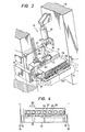
- FIG. 2 is a side elevation showing the entirety of a roll grinding apparatus 11 and FIG. 3 is a perspective view of a top roll grinding apparatus 11.
- a bottom roll grinding apparatus is analogous to the top roll grinding apparatus in structure and function, the only difference being the position in which they are installed. As such, similar parts are designated by similar reference characters, with the description thereof omitted.
- a pair of guides 15 inclined forward or toward a roll 5 are provided in a-housing 13.
- the housing 13 also carries a reciprocatable frame 17 through said guides 15.
- a swingable hydraulic cylinder 21 is also attached to the housing 13 through a pin 22.
- One end of a crank 26 is connected to the rod 23 of the hydraulic cylinder 21 through a pin 25, with the middle part of the crank 26 fastened to a shaft 27 rotatably fitted to the housing 13.
- To the other end of the crank 26 is connected a link bar 29 through a pin 28, with the other end of the link bar connected to the rear end of said frame 17 by means of a pin 30.
- the cylinder rod 23, crank 26 and link bar 29 make up a linkage.
- the frame 17 is therefore moved back and forth by the action of the hydraulic cylinder 21.
- a pair of rails 32 extending along the axis of the roll and inclined toward one side of the frame 17 is provided near the front end of the frame 17.
- a traversable block-shaped casing 34 is mounted on the rails 32.
- the casing 34 has seven holes 37 that open forward as shown in FIG. 4, with a sleeve 38 fitted in each of the holes 37.
- a hydraulic cylinder 41 is provided near the rear end of the frame 17, with the rod 42 thereof connected to the casing 34 through a coupling 43. By the action of the hydraulic cylinder 41, the casing 34 diagonally moves over the rails 32 to and from the side of the frame 17.
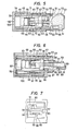
- FIGs. 5 to 9 show the details of a grindstone holder 45. While FIGs. 5 to 7 show a grindstone 57 sent out of a grindstone holding portion 53 without touching the roll 5, FIGs. " 8 and 9 show the grindstone 57 kept in contact with the.roll 5.
- the grindstone holder 45 comprises a cylindrical sliding portion 46 and the grindstone holding portion 53 that is a forward continuation thereof.
- the sliding portion 46 is slidably fitted in a guide hole 39 in said sleeve 38.
- the precision-finished internal surface of the guide hole 39 and external surface of the sliding portion 46 offers little resistance to each other, thereby permitting the grindstone holder 45 to move back and forth smoothly.
- the grindstone holding portion 53 has a square hole 54 in which a plate-shaped grindstone 57 is reciprocatably fitted.
- the grindstone 57 is fastened to the grindstone holding portion 53 by means of a clamp mechanism 59 to be described next.
- a bellows 56 is provided between the sliding portion 46 and the grindstone holding portion 53 to prevent dust and vapor from entering the clearance between the sliding portion 46 and the sleeve 38.
- a longitudinal taper 55 is provided near the front end of one side wall 54 of the grindstone holding portion 53.
- a clamp rod 60 reciprocatably passes through a bulkhead 48 between the sliding portion 46 and grindstone holding portion 53:
- a wedge 61 and a spring seat 62 are provided to the front and rear end of the clamp rod 60, respectively.
- a spring 63 is inserted between the spring seat 62 and the bulkhead 48.
- the double-acting pneumatic cylinder 65 is positioned inside the sliding portion 46 of each grindstone holder 45, with the cylinder tube 66 fastened to the rear wall 35 of the casing 34.
- a tubular piston rod 72 passing through the cover 67 and bulkhead 48 forms a single-acting pneumatic cylinder 75 in conjuction with a ram 76 inserted therein.
- the rear wall 35 of the casing 34 is provided with a passage 82 through which compressed air is supplied to the head-side chamber 68 of the double-acting pneumatic cylinder 65 and to the rod-side chamber 69 thereof through a pipe 83. Compressed air is also supplied from the rod-side chamber 69 to the ram chamber 73 through a passage 84 in the piston 71.
- the passage 82 and the pipe 83 are independent from each other and respectively receive the supply of compressed air through a flexible tube 85 shown in FIG. 2.
- Each flexible tube 85 is provided with a stop valve and a pressure-regulating valve (not shown).
- a grindstone stopper 87 is provided to the front portion of the grindstone holder 45.
- a rod 88 passes through the head 49 of the sliding portion of the grindstone holder 45, while an arm 91 having a pawl 90 at the front end thereof is rotatably attached to the grindstone holding portion through a shaft 92.
- a cam 93 is attached to a point some distance away from the front end of the rod 88 through the shaft 92.
- the rear end of the rod 88 constitutes a spring seat 95, with a spring 96 interposed between the spring seat 95 and said bulkhead 48.
- a roller 89 to actuate the cam 93 is pivotally fitted to the front end of the rod 88.
- the casing 34 has a plunger chamber 98 that extends forward in the bottom 36 thereof.
- the front end of a plunger 99 inserted in the plunger chamber 98 is in contact with the flange 50 at the rear end of the grindstone holder 45.
- the plunger chamber 98 and plunger 99 make up a balancing mechanism 97.
- With compressed air supplied from a passage 100 to the plunger chamber 98 the plunger 99 pushes backward the grindstone holder 45.
- the grindstone holder 45 tends to jump out of the casing 34 under its own weight but supported by the plunger 99 so that the weight of the grindstone holder 45 is balanced with the thrust exerted by the plunger 99. Being installed in a horizontal position as shown in FIG. 2, the bottom roll grinding apparatus 11 requires no balancing mechanism 97.
- a wiper 103 is attached to the front end of the frame 17. Being kept in close contact with the roll 5 between the grindstone 57 and the strip S, the wiper 103 clears the ground chips off the roll surface, thus preventing the strip surface from being damaged thereby.
- FIG. 10 schematically shows a grinding control system which essentially comprises a sensor 111, a control computer (TOSBAC 7/70G) 121 and a controller 123.
- the sensor 111 has a roll profile meter 112 and a grindstone position detector 118.
- a guide rail 115 is . provided across the housing 13 parallel to the shaft of the roll 5.
- a carriage 113 which is driven by a motor 114 along the guide rail 115, is mounted thereon.
- the carriage 113 carries the roll profile meter 112 that determines the shape of the roll surface.
- An air micrometer, a water micrometer or an eddy-current displacement meter, for example, may be used as the roll profile meter 112.
- the grindstone position detector 118 is an ordinary displacement meter that senses the position of the casing 34 accommodating the grindstone holder 45 in the direction of the roll axis.
- the strip width w and the roll-body length A are preset in the control computer 121, with a detection signal p inputted from the roll profile meter 112.
- the controller 123 To the controller 123 are inputted a detection signal d from the grindstone position detector 118 and a control signal c, which instructs a grinding mode (showing whether the grindstone is grinding the roll surface or not) to each grindstone 57, from the control computer.121.
- the controller 123 outputs an operation signal m to the control valve 125 of the hydraulic cylinder 41 that traverses the casing 34 according to the signal c from the control computer to control the stroke and cycle of the reciprocative motion of the casing.
- the controller 123 also outputs an operation signal m to the control valve 127 of the pneumatic cylinder 65 that moves back and forth the grindstone holder 45 according to the signals c and d.
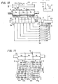
- FIG. 11 illustrates a roll grinding method, showing a worn-off roll, the loci drawn by the reciprocating grindstones over the surface of the rotating roll, and the grinding modes of the grindstones in a time-series arrangement.
- FIG. 12 is a flow chart showing the sequence of roll grinding control.
- the roll 5 usually wears off in a portion 5b where the strip passes, thereby creating a difference q in diameter between the portion 5b and the remaining portions 5a and 5c where the strip does not pass.
- the portions 5a and 5c must be ground off.
- the profile of the roll surface is directly determined along the roll axis by use of the roll profile meter 112 at a proper time during operation. '
- the control computer 121 determines the profile of the worn-off roll 5, pinpoints the portions 5a and 5c requiring grinding, and the required grinding time.
- the limits P and Q within which the projection of the grindstone 57 beyond the stepped portion and the roll edge should be kept are determined.
- the individual grindstones 57 are controlled so that the over-projecting grindstone 57 is withdrawn away from the roll surface.
- the grind- stones 57a and 57g are withdrawn when the projection beyond the roll edge exceeds the limit Q while the grindstones 57c and 57e are withdrawn when the projection beyond the stepped portion exceeds the limit P, shifting from the grinding mode to the non-grinding mode.
- the grindstones 57b and 57f are at all times in the grinding mode, whereas the grindstone 57d is always withdrawn and in the non-grinding mode.
- the advance and withdrawal of the grindstones 57 are timed according to the signal c from the control computer 121 and the signal d from the grindstone position detector 118.
- the hatched rectangle show a grindstone in the grinding mode and the blank rectangle indicates a grindstone in the non-grinding mode.
- the roll surface is always kept smooth by determining the profile of the roll 5 as desired and grinding off only the unpassed portions 5a and 5c.
- the whole surface may be ground uniformly. If any biased wear is detected on the roll 5 by the roll profile meter 112, corrective grinding can be applied as well.
- the hydraulic cylinder 21 is actuated to move the casing 34 back and forth diagonally.
- the grindstone 57 pressed against the roll surface moves backs and forth therealong with the diagonal reciprocation of the casing 34. That is, the grindstone 57 moves back and forth spirally over the roll surface.
- the profile of the roll 5 may be either measured directly with the roll profile meter or estimated from the shape of the rolled strip S.
- the roll profile can also be estimated from the calculation based on such rolling conditions as the load applied in rolling, overall length of strip, properties of steel, properties and temperature of the roll. Grinding is accomplished by pressing against the roll only such grindstones 57 as are required by the desired profile thereof.
- the grindstone 57 is sent out of the grindstone holding portion 53 of the grindstone holder 57 as follows.
- the double-acting pneumatic cylinder 65 is actuated to draw the grindstone holder 45 into the casing 34.
- the cover 67 of the double-acting pneumatic cylinder 65 pushes the rod 60 of the clamp mechanism 59 and the rod 88 of the stopper mechanism 87.
- the arm 91 of the stopper mechanism 87 turns to bring the pawl 90 immediately in front of the end surface of the grindstone holding portion 53, thereby disengaging the grindstone 57.
- the space between the end surface of the grindstone holding portion 53 and the pawl 90 is set equal to the desired amount of pay-out.
- the roll grinding apparatus 11 of this invention comprises the traversable casing 34 mounted on the reciprocatable frame 17, the casing 34 carrying a plurality of slidable grindstone holders 45.
- the grindstone 57 is fastened to each grindstone holder 45.
- This arrangement permits rapidly setting all grindstones in the grinding position. Being slidably fitted in the casing 34, the grindstone holder 45 can move smoothly, which, in turn, assures the smooth motion of the grindstone 57. This means that the grindstone 57 is at all times pressed against the roll surface with a constant pressure, thus assuring precision grinding.
- the casing may be traversed by an electric motor.
- the traversing roll profile meter may also be replaced with a plurality of roll profile measuring heads disposed along the roll axis.
Landscapes
- Engineering & Computer Science (AREA)
- Mechanical Engineering (AREA)
- Grinding Of Cylindrical And Plane Surfaces (AREA)
Abstract
Description
- This invention relates to a roll grinding apparatus for rolling mills, and more particularly to a roll grinding apparatus that dresses the profile of used work and back-up rolls of plate mills and pinch rolls of coilers by grinding in-line.
- With a view to increasing the efficiency of rolling operation, several methods of grinding work. and other rolls in line while the rolling operation is in progress have been proposed as in the Japanese Utility Model Gazette No. 45037 of 1974, Provisional Patent Publications Nos. 58951 of 1978, 3989 of 1979, 65061 of 1980 and 53806 of 1981.
- Previously the inventor proposed a method of grinding rolling mill rolls which comprises reciprocating a grindstone pressed against the surface of a roll not only in the direction parallel to the axis of the roll but also in the direction in which the roll rotates (Provisional Patent Publication No. 14010 of 1981). By this method, the roll surface can be ground efficiently and precisely without causing grindstone blocking and abrasion. In this method, the roll surface is ground with a plurality of rectangular grindstones reciprocatably disposed along the roll axis. While being kept in close contact with the roll surface, the grindstones are driven in such a manner as to make a motion in which said two reciprocative movements are combined.
- To grind the roll surface to a desired shape with a precision on the order of µm according to the method just described, it is necessary to press the individual grindstones against the roll surface with an appropriate amount of pressure and put the grindstones in exact working position with respect to the roll to be dressed. For increasing the operational efficiency, it is also necessary to rapidly place the grindstones in the desired position. So far, however, no concrete grinding apparatus satisfying such requirements has been proposed.
- This invention has been made to solve the above- mentioned problems with the conventional roll grinding apparatus. The object of this invention is to provide a roll grinding apparatus for rolling mills that permits precise grinding of rolls and rapidly setting a group of grindstones in working position.
- A roll grinding apparatus according to this invention comprises a housing adjoining a roll to be ground, guides attached to the housing in such a manner as to extend perpendicularly to the axis of the roll, a frame attached to the housing in such a manner as to be reciprocated along the guides, means reciprocating the frame, inclined guides provided to the frame in such a manner as to extend along the roll axis and incline toward one e'nd of the frame, a casing having a plurality of guide holes opening to the roll side disposed along the roll axis and traversably mounted on the inclined guides, means reciprocating the casing laterally, a grindstone holder reciprocatably fitted in each of the guide holes, a rectangular grindstone held at the tip of the grindstone holder, and grindstone reciprocating means provided to each grindstone holder.
- The housing may be either shared in common by a rolling stand or provided separately. The frame reciprocating means and casing traversing means should preferably be a hydraulic cylinder or motor. A pneumatic cylinder or an electric motor may also serve the purpose. The guide hole and the sliding portion of the grindstone holder are precision-finished so that the grindstone holder smoothly slides through the guide hole while being held in close contact therewith. The grindstone holder reciprocating means is a pneumatic or hydraulic double-acting cylinder. With this means placed inside the sliding portion of the grindstone holder, the holder has a high enough rigidity to withstand considerable vibration and chattering, with a resulting increase in reliability. Being mechanically interlocked with a grindstone clamp, stopper and extending means, the grindstone holder needs only one drive means and, therefore, can be readily installed even on an existing mill where available space might be limited.
- Guide rails, rollers, sliding plates and other similar means may be used as the inclined guides which allow the casing to be moved diagonally back and forth to and from one end thereof.
- The apparatus thus constructed is provided to each of the top and bottom rolls.
- When there arises a need to mount or dismount a roll on or from a rolling stand for roll changing or other reasons, the frame is withdrawn by actuating the frame reciprocating means. Then, the grindstone is detached from the roll along with the casing, back into a place where the grindstone does not interfere with the mounting and dismounting of the roll. When the roll has been mounted on the rolling stand, the frame reciprocating means is actuated to advance the frame until the grindstone is brought close to the roll surface.
- In grinding a roll, the grindstone holder reciprocating means is actuated to send out the grindstone holder out of the casing, whereupon the grindstone is pressed against the roll surface and the frame is reciprocated by means of the casing traversing means. Then, the grindstone dresses the roll surface while spirally moving back and forth therealong. The amount of dressing is controlled by adjusting the force with which the grindstone is pressed against the roll surface and the grinding time.
- When no grinding is done, the grindstone holder is withdrawn away from the roll surface by means of the grindstone holder reciprocating means.
-
- FIG. 1 is a schematic illustration of a rolling mill line on which a roll grinding apparatus according to this invention is installed.
- FIG. 2 is an overall side elevation of a roll grinding apparatus of this invention.
- FIG. 3 is a perspective view of a top roll grinding apparatus.
- FIG. 4 is a cross-sectional view taken along the line IV-IV of FIG. 2.
- FIGs. 5 to 9 show details of a grindstone holder according to this invention. FIGs. 5, 6 and 7 are a sectional plan view, a sectional side elevation and a front view showing a grindstone sent out of the grindstone holder without touching a roll to be grounded, respectively.
- FIGs. 8 and 9 are a sectional plan view and a sectional side elevation showing the grindstone kept in contact with the roll, respectively.
- FIG. 10 is a schematic diagram showing a grinding control system.
- FIG. 11 illustrates a roll grinding method that is implemented by employing a roll grinding apparatus of this invention.
- FIG. 12 is a flow chart showing the sequence of roll grinding control according to this invention.
- Now a preferred embodiment of this invention will be described by reference to/accompanying drawings.
- FIG. 1 shows an example in which a roll grinding apparatus of this invention is applied to a hot-strip mill comprising a reheating
furnace 1, a roughingstand 2, afinishing mill train 4 and acoiler 6. The roll grinding apparatus of this invention is best fitted for grinding such rolls as the work rolls 3 of the roughingstand 2 and the work rolls 5 of thefinishing stand 4 of a hot-strip mill that wear off heavily during use. It is also applicable to such rolls as the pinch rolls 7 of thecoiler 6 and the rolls of a tandem and reversing mill that are employed in a cold-strip mill, not shown, whose wear presents various problems. In addition to the simple four-high mill shown in the described example, the finishingmill 4 may also be of the six-high, cross-country or other types. - The arrow A shows the direction in which the strip S travels and the arrow B indicates the direction in which the rolls rotate.
- FIG. 2 is a side elevation showing the entirety of a
roll grinding apparatus 11 and FIG. 3 is a perspective view of a toproll grinding apparatus 11. A bottom roll grinding apparatus is analogous to the top roll grinding apparatus in structure and function, the only difference being the position in which they are installed. As such, similar parts are designated by similar reference characters, with the description thereof omitted. As illustrated, a pair ofguides 15 inclined forward or toward aroll 5 are provided in a-housing 13. - The
housing 13 also carries areciprocatable frame 17 through saidguides 15. - A swingable
hydraulic cylinder 21 is also attached to thehousing 13 through apin 22. One end of acrank 26 is connected to the rod 23 of thehydraulic cylinder 21 through apin 25, with the middle part of thecrank 26 fastened to ashaft 27 rotatably fitted to thehousing 13. To the other end of thecrank 26 is connected a link bar 29 through apin 28, with the other end of the link bar connected to the rear end of saidframe 17 by means of apin 30. Thus, the cylinder rod 23,crank 26 and link bar 29 make up a linkage. Theframe 17 is therefore moved back and forth by the action of thehydraulic cylinder 21. - A pair of
rails 32 extending along the axis of the roll and inclined toward one side of theframe 17 is provided near the front end of theframe 17. - A traversable block-
shaped casing 34 is mounted on therails 32. Thecasing 34 has sevenholes 37 that open forward as shown in FIG. 4, with asleeve 38 fitted in each of theholes 37. - A
hydraulic cylinder 41 is provided near the rear end of theframe 17, with therod 42 thereof connected to thecasing 34 through acoupling 43. By the action of thehydraulic cylinder 41, thecasing 34 diagonally moves over therails 32 to and from the side of theframe 17. - FIGs. 5 to 9 show the details of a
grindstone holder 45. While FIGs. 5 to 7 show a grindstone 57 sent out of agrindstone holding portion 53 without touching theroll 5, FIGs."8 and 9 show thegrindstone 57 kept in contact withthe.roll 5. - As will be seen, the
grindstone holder 45 comprises a cylindrical slidingportion 46 and thegrindstone holding portion 53 that is a forward continuation thereof. - The sliding
portion 46 is slidably fitted in aguide hole 39 in saidsleeve 38. The precision-finished internal surface of theguide hole 39 and external surface of the slidingportion 46 offers little resistance to each other, thereby permitting thegrindstone holder 45 to move back and forth smoothly. - The
grindstone holding portion 53 has asquare hole 54 in which a plate-shapedgrindstone 57 is reciprocatably fitted. Thegrindstone 57 is fastened to thegrindstone holding portion 53 by means of aclamp mechanism 59 to be described next. A bellows 56 is provided between the slidingportion 46 and thegrindstone holding portion 53 to prevent dust and vapor from entering the clearance between the slidingportion 46 and thesleeve 38. - A
longitudinal taper 55 is provided near the front end of oneside wall 54 of thegrindstone holding portion 53. Aclamp rod 60 reciprocatably passes through abulkhead 48 between the slidingportion 46 and grindstone holding portion 53: Awedge 61 and aspring seat 62 are provided to the front and rear end of theclamp rod 60, respectively. Aspring 63 is inserted between thespring seat 62 and thebulkhead 48. - When the
grindstone holder 45 moves backward by the action of a double-actingpneumatic cylinder 65, thespring seat 62 strikes thecover 67 of the double-actingpneumatic cylinder 65 and theclamp rod 60 moves forward with respect to thegrindstone holder 45. As a consequence, thegrindstone 57 is released from thewedge 61 to move back and forth freely. When thegrindstone holder 45 moves forward, thespring seat 62 is separated from thecover 67 of the double-actingpneumatic cylinder 65 and sent backward by the force of thespring 63. Then, thewedge 61 enters the clearance between the grindstone 57 and the taperedportion 55 of theside wall 54, thereby fastening thegrindstone 57 to thegrindstone holder 45. Since the plate-shapedgrindstone 57 is grasped from both sides, the grindstone will not be damaged by the force of the clamp even if the grindstone may have deformed slightly or any foreign matter has entered the holder. - The double-acting
pneumatic cylinder 65 is positioned inside the slidingportion 46 of eachgrindstone holder 45, with thecylinder tube 66 fastened to therear wall 35 of thecasing 34. Atubular piston rod 72 passing through thecover 67 andbulkhead 48 forms a single-actingpneumatic cylinder 75 in conjuction with aram 76 inserted therein. - The
rear wall 35 of thecasing 34 is provided with apassage 82 through which compressed air is supplied to the head-side chamber 68 of the double-actingpneumatic cylinder 65 and to the rod-side chamber 69 thereof through apipe 83. Compressed air is also supplied from the rod-side chamber 69 to theram chamber 73 through apassage 84 in thepiston 71. Thepassage 82 and thepipe 83 are independent from each other and respectively receive the supply of compressed air through aflexible tube 85 shown in FIG. 2. Eachflexible tube 85 is provided with a stop valve and a pressure-regulating valve (not shown). - When compressed air is supplied to the
ram chamber 73, theram 76 moves forward to bring theflange 77 at the front end thereof in contact with the rear surface of thegrindstone 57 which is, in turn, pushed out of thegrindstone holding portion 53. When compressed air is supplied to the piston-side chamber 68 of the double-actingpneumatic cylinder 65, thepiston rod 72 moves forward to bring theflange 74 at the front end thereof in contact with the rear surface of theram flange 77, then advancing further to push the entirety of thegrindstone holder 45 out of thecasing 34. Thewhole grindstone holder 45 moves backward when compressed air is supplied to the cover-side chamber 69. - A
grindstone stopper 87 is provided to the front portion of thegrindstone holder 45. Arod 88 passes through thehead 49 of the sliding portion of thegrindstone holder 45, while anarm 91 having apawl 90 at the front end thereof is rotatably attached to the grindstone holding portion through ashaft 92. Acam 93 is attached to a point some distance away from the front end of therod 88 through theshaft 92. The rear end of therod 88 constitutes aspring seat 95, with aspring 96 interposed between thespring seat 95 and saidbulkhead 48. Aroller 89 to actuate thecam 93 is pivotally fitted to the front end of therod 88. - When the
grindstone holder 45 withdraws, thecylinder cover 67 pushes forward therod 88, thereby rotating thecam 93 which, in turn, causes thearm 91 to rotate into a horizontal position, whereupon thepawl 90 stands up to prevent the grindstone 57 from moving forward. When thegrindstone holder 45 moves forward, thespring seat 95 is released from thecylinder cover 67 and therod 88 moves backward by the force of thespring 96. As a consequence, thecam 93 rotates to turn thearm 91 clockwise, thereby disengaging thepawl 90 from the front end of thegrindstone 57. - The
casing 34 has aplunger chamber 98 that extends forward in the bottom 36 thereof. The front end of aplunger 99 inserted in theplunger chamber 98 is in contact with theflange 50 at the rear end of thegrindstone holder 45. Theplunger chamber 98 andplunger 99 make up abalancing mechanism 97. With compressed air supplied from apassage 100 to theplunger chamber 98, theplunger 99 pushes backward thegrindstone holder 45. Because the toproll grinding apparatus 11 inclines forward as shown in FIG. 2, thegrindstone holder 45 tends to jump out of thecasing 34 under its own weight but supported by theplunger 99 so that the weight of thegrindstone holder 45 is balanced with the thrust exerted by theplunger 99. Being installed in a horizontal position as shown in FIG. 2, the bottomroll grinding apparatus 11 requires nobalancing mechanism 97. - A
wiper 103 is attached to the front end of theframe 17. Being kept in close contact with theroll 5 between the grindstone 57 and the strip S, thewiper 103 clears the ground chips off the roll surface, thus preventing the strip surface from being damaged thereby. - FIG. 10 schematically shows a grinding control system which essentially comprises a
sensor 111, a control computer (TOSBAC 7/70G) 121 and acontroller 123. Thesensor 111 has aroll profile meter 112 and agrindstone position detector 118. Aguide rail 115 is . provided across thehousing 13 parallel to the shaft of theroll 5. Acarriage 113, which is driven by amotor 114 along theguide rail 115, is mounted thereon. Thecarriage 113 carries theroll profile meter 112 that determines the shape of the roll surface. An air micrometer, a water micrometer or an eddy-current displacement meter, for example, may be used as theroll profile meter 112. Thegrindstone position detector 118 is an ordinary displacement meter that senses the position of thecasing 34 accommodating thegrindstone holder 45 in the direction of the roll axis. - The strip width w and the roll-body length A are preset in the
control computer 121, with a detection signal p inputted from theroll profile meter 112. - To the
controller 123 are inputted a detection signal d from thegrindstone position detector 118 and a control signal c, which instructs a grinding mode (showing whether the grindstone is grinding the roll surface or not) to each grindstone 57, from the control computer.121. Thecontroller 123 outputs an operation signal m to thecontrol valve 125 of thehydraulic cylinder 41 that traverses thecasing 34 according to the signal c from the control computer to control the stroke and cycle of the reciprocative motion of the casing. Thecontroller 123 also outputs an operation signal m to thecontrol valve 127 of thepneumatic cylinder 65 that moves back and forth thegrindstone holder 45 according to the signals c and d. - Now a method of grinding the
roll 5 using theroll grinding apparatus 11 just described will be explained in the following. - FIG. 11 illustrates a roll grinding method, showing a worn-off roll, the loci drawn by the reciprocating grindstones over the surface of the rotating roll, and the grinding modes of the grindstones in a time-series arrangement. FIG. 12 is a flow chart showing the sequence of roll grinding control.
- As a result of repeated rolling, the
roll 5 usually wears off in aportion 5b where the strip passes, thereby creating a difference q in diameter between theportion 5b and the remainingportions portions roll profile meter 112 at a proper time during operation.' On the basis of the difference q derived from the measurement p, the strip width w and the roll-body length l, thecontrol computer 121 determines the profile of the worn-off roll 5, pinpoints theportions - To grind off only the
portions necessary grindstones 34 are chosen and pressed against the surface of the rotating roll. These operations are carried out as follows in accordance with the instruction m that is outputted from thecontroller 123 on the basis of the control signal c from thecontrol computer 121. - To grind off the
unpassed portions roll 5, the limits P and Q within which the projection of thegrindstone 57 beyond the stepped portion and the roll edge should be kept are determined. When the projection of agrindstone 57 moving with the traversing of thecasing 34 exceeds the preset limit P or Q, theindividual grindstones 57 are controlled so that theover-projecting grindstone 57 is withdrawn away from the roll surface. In FIG. 12, the grind-stones grindstones 57c and 57e are withdrawn when the projection beyond the stepped portion exceeds the limit P, shifting from the grinding mode to the non-grinding mode. Pressed forward against the roll surface, thegrindstones grindstone 57d is always withdrawn and in the non-grinding mode. The advance and withdrawal of thegrindstones 57 are timed according to the signal c from thecontrol computer 121 and the signal d from thegrindstone position detector 118. In the figure, the hatched rectangle show a grindstone in the grinding mode and the blank rectangle indicates a grindstone in the non-grinding mode. - Thus, the roll surface is always kept smooth by determining the profile of the
roll 5 as desired and grinding off only theunpassed portions roll 5 by theroll profile meter 112, corrective grinding can be applied as well. - In grinding the
roll 5 as described above, theframe 17 is moved forward to the grinding position by means of thehydraulic cylinder 21. At this point, thegrindstone holder 45 is still held inside thecasing 34 as shown in FIGs. 5 and 6. - When there arises a need to correct the profile of the
roll 5 during rolling, compressed air is supplied to the double-actingpneumatic cylinder 65 of agrindstone holder 45 corresponding to the portion requiring grinding in the direction of the roll axis, whereby thegrindstone holder 45 is sent out of thecasing 34. As shown in FIGs. 8 and 9, thegrindstone 57 is fastened inside thegrindstone holding portion 53 by theclamp mechanism 59 and thepawl 90 disengages from the front end of thegrindstone 57. Thegrindstone 57 andgrindstone holder 45 are integrally pushed by the double-actingpneumatic cylinder 65 until the roll surface is reached. With the compressed air controlled appropriately, thegrindstone 57 is kept in contact with the roll surface with the desired pressure. - Simultaneously with the above operation, the
hydraulic cylinder 21 is actuated to move thecasing 34 back and forth diagonally. Thegrindstone 57 pressed against the roll surface moves backs and forth therealong with the diagonal reciprocation of thecasing 34. That is, thegrindstone 57 moves back and forth spirally over the roll surface. - The profile of the
roll 5 may be either measured directly with the roll profile meter or estimated from the shape of the rolled strip S. The roll profile can also be estimated from the calculation based on such rolling conditions as the load applied in rolling, overall length of strip, properties of steel, properties and temperature of the roll. Grinding is accomplished by pressing against the roll onlysuch grindstones 57 as are required by the desired profile thereof. - When worn off as a result of grinding, the
grindstone 57 is sent out of thegrindstone holding portion 53 of thegrindstone holder 57 as follows. First, the double-actingpneumatic cylinder 65 is actuated to draw thegrindstone holder 45 into thecasing 34. Then, thecover 67 of the double-actingpneumatic cylinder 65 pushes therod 60 of theclamp mechanism 59 and therod 88 of thestopper mechanism 87. As a consequence, thearm 91 of thestopper mechanism 87 turns to bring thepawl 90 immediately in front of the end surface of thegrindstone holding portion 53, thereby disengaging thegrindstone 57. The space between the end surface of thegrindstone holding portion 53 and thepawl 90 is set equal to the desired amount of pay-out. At the same time, compressed air is supplied to theram chamber 73 of the single-actingcylinder 75 to cause theram 77 to push thegrindstone 57 out of thegrindstone holding portion 53. On striking against thepawl 90, thegrindstone 57 has been paid out over the desired distance. - The
roll grinding apparatus 11 of this invention comprises thetraversable casing 34 mounted on thereciprocatable frame 17, thecasing 34 carrying a plurality ofslidable grindstone holders 45. Thegrindstone 57 is fastened to eachgrindstone holder 45. This arrangement permits rapidly setting all grindstones in the grinding position. Being slidably fitted in thecasing 34, thegrindstone holder 45 can move smoothly, which, in turn, assures the smooth motion of thegrindstone 57. This means that thegrindstone 57 is at all times pressed against the roll surface with a constant pressure, thus assuring precision grinding. - This invention is by no means limited to the preferred embodiment described above. For instance, the casing may be traversed by an electric motor. The traversing roll profile meter may also be replaced with a plurality of roll profile measuring heads disposed along the roll axis.
Claims (7)
- (1) A roll grinding apparatus for use on a rolling mill which comprises:a housing provided next to a roll;a guide provided in the housing in such a manner as to extend perpendicularly to the axis of the roll;a frame attached to the housing in such a manner as to move back and forth along the guide;means reciprocating the frame;an inclined guide provided to the frame in such a manner as to extend along the roll axis and incline toward one end of the frame;a casing provided with a plurality of guide holes opening toward the roll side and arranged along the roll axis and traversably mounted on the inclined guide;means traversing the casing;a grindstone holder slidably inserted in each guide hole;a rectangular parallelepiped-shaped grindstone held in the front portion of the grindstone holder; andmeans reciprocating the grindstone provided to each grindstone holder.
- (2) A roll grinding apparatus according to claim 1, in which the casing has means for clamping the grindstone, the grindstone clamping means consisting of a wedge connected to the casing proper through a rod extending to the tip of the grindstone holder, the wedge being interposed between the grindstone holder and. the grindstone and adapted to clamp the grindstone as the grindstone holder advances.
- (3) A roll grinding apparatus according to claim 1 or 2, in which the casing has a grindstone stopper, the grindstone stopper consisting of a rod extending to the grindstone holding portion of the grindstone holder, an arm having a pawl engaging with the front end of the grindstone at the front end thereof and rotatably attached to the grindstone holding portion through a rotating shaft at the rear end thereof and-a cam mechanism attached to the front end of said rod and said rotating shaft and being adapted to restrict the advance of the grindstone with the grindstone holder.
- (4) A roll grinding apparatus according to any of claims 1 to 3, in which the grindstone reciprocating means consists of a double-acting fluid-pressure actuated cylinder, the double-acting fluid-pressure actuated cylinder comprising a cylinder tube with the head end thereof fastened to said casing in the grindstone holder, the cylinder tube having a head-side chamber to which an actuating fluid is supplied, a piston rod passing through the cover of said cylinder, the piston rod being tubular to form a ram chamber to which the actuating fluid is supplied through the rod-side chamber of the cylinder tube, and a ram inserted in the ram chamber of the piston rod so that the front end thereof pushes the rear end of the grindstone.
- (5) A roll grinding apparatus according to any of claims 1 tc 4, in which the grindstone is held breadthwise by the grindstone holder.
- (6) A roll grinding apparatus according to any of claims 1 tc 5, in which the casing has a longitudinally extending plunger chamber holding a plunger inserted therein, the front end of the plunger being kept in contact with the grindstone holder in such a manner as to push the grindstone holder backward.
- (7) A roll grinding apparatus according to any of claims 1 to 6, which comprises means sensing the profile of the roll surface, means sensing the position of the casing in the direction of the roll axis, a computer that selects one or more grindstones to grind the roll surface on the basis of the signals sent from said profile and casing position sensing means, and control means to output an operation signal to the grindstone reciprocating means according to the signal from the computer.
Applications Claiming Priority (2)
| Application Number | Priority Date | Filing Date | Title |
|---|---|---|---|
| JP40443/84 | 1984-03-05 | ||
| JP59040443A JPS60184411A (en) | 1984-03-05 | 1984-03-05 | Roll grinding device in rolling installation |
Publications (3)
| Publication Number | Publication Date |
|---|---|
| EP0154319A2 true EP0154319A2 (en) | 1985-09-11 |
| EP0154319A3 EP0154319A3 (en) | 1986-03-05 |
| EP0154319B1 EP0154319B1 (en) | 1989-10-18 |
Family
ID=12580785
Family Applications (1)
| Application Number | Title | Priority Date | Filing Date |
|---|---|---|---|
| EP85102413A Expired EP0154319B1 (en) | 1984-03-05 | 1985-03-04 | Roll grinding apparatus for rolling mills |
Country Status (5)
| Country | Link |
|---|---|
| US (1) | US4619080A (en) |
| EP (1) | EP0154319B1 (en) |
| JP (1) | JPS60184411A (en) |
| KR (1) | KR880002338B1 (en) |
| DE (1) | DE3573741D1 (en) |
Cited By (9)
| Publication number | Priority date | Publication date | Assignee | Title |
|---|---|---|---|---|
| FR2600919A1 (en) * | 1986-07-03 | 1988-01-08 | Sofresid | Method and device for dressing (retouching), because of wearing, the rolls of a rolling mill, on the rolling line |
| FR2603827A1 (en) * | 1986-09-12 | 1988-03-18 | Kocks Technik | DEVICE FOR MACHINING BY CHIP REMOVAL OF WORKING SURFACES OF CYLINDERS |
| AU609005B2 (en) * | 1989-05-19 | 1991-04-18 | Mitsubishi Jukogyo Kabushiki Kaisha | Method for grinding roll |
| FR2685880A1 (en) * | 1992-01-06 | 1993-07-09 | Clecim Sa | Apparatus for cleaning a cylindrical roller, and especially a rolling-mill roll |
| EP0812632A1 (en) * | 1996-06-13 | 1997-12-17 | DANIELI & C. OFFICINE MECCANICHE S.p.A. | In-line grinding device for mill rolls and/or pinch rolls |
| WO2012001032A1 (en) * | 2010-07-02 | 2012-01-05 | Sms Siemag Ag | Polishing device |
| CN102490108A (en) * | 2011-12-13 | 2012-06-13 | 文登威力高档工具有限公司 | Abrasive cloth wheel polisher for double-faced curve grinding and polishing method thereof |
| WO2014191357A1 (en) * | 2013-05-27 | 2014-12-04 | Hydro Aluminium Rolled Products Gmbh | Rolling device and method for conditioning a roll surface |
| CN113787432A (en) * | 2021-08-23 | 2021-12-14 | 朱泽妍 | Spare part production facility for manufacturing |
Families Citing this family (16)
| Publication number | Priority date | Publication date | Assignee | Title |
|---|---|---|---|---|
| JPS6390504U (en) * | 1986-12-01 | 1988-06-11 | ||
| KR100277320B1 (en) * | 1992-06-03 | 2001-01-15 | 가나이 쓰도무 | Rolling mill and rolling method with on-line roll grinding device and grinding wheel |
| JP3022702B2 (en) * | 1993-05-27 | 2000-03-21 | 株式会社日立製作所 | Online roll mill |
| US5569060A (en) * | 1993-05-27 | 1996-10-29 | Hitachi, Ltd. | On-line roll grinding apparatus |
| DE19633855A1 (en) * | 1996-08-16 | 1998-02-19 | Mannesmann Ag | Method and device for regrinding the rolls installed in hot strip rolling mills |
| US6408666B1 (en) * | 2000-09-11 | 2002-06-25 | Hitachi, Ltd. | Rolling mill and rolling method |
| RU2175583C2 (en) * | 2000-01-25 | 2001-11-10 | Открытое акционерное общество "Новолипецкий металлургический комбинат" | Method for preparing rolling rolls of cold rolling mills for rolling operation |
| US6827530B2 (en) * | 2001-07-10 | 2004-12-07 | Self Leveling Machines, Inc. | Symmetrical mill |
| KR100960376B1 (en) * | 2003-06-13 | 2010-05-28 | 주식회사 포스코 | Back-Roll Grinding Machine for Scoring Machine |
| JP2010105050A (en) * | 2010-02-19 | 2010-05-13 | Jfe Steel Corp | Hot finishing mill train and hot-rolling mill train provided with on-line roll grinder |
| KR101330544B1 (en) * | 2011-07-28 | 2013-11-18 | 현대제철 주식회사 | Apparatus for measuring shape of slab |
| KR101330546B1 (en) * | 2011-07-28 | 2013-11-18 | 현대제철 주식회사 | Grinding method for work roller in rolling mill |
| US9617691B2 (en) * | 2013-03-15 | 2017-04-11 | Greenleaf Technology Corporation | Rail re-profiling method and apparatus |
| CN104307879A (en) * | 2014-11-10 | 2015-01-28 | 江苏亨特宏业重工有限公司 | Dirt removing device for cold rolling mill roller for aluminum profile production line |
| CN112139872B (en) * | 2020-09-01 | 2022-04-05 | 武汉市科迈机械制造有限责任公司 | Part polishing device for mechanical production and use method thereof |
| CN117161858B (en) * | 2023-11-02 | 2023-12-29 | 上海昭晟机电(江苏)有限公司 | Cathode titanium roller surface grinding treatment equipment |
Family Cites Families (13)
| Publication number | Priority date | Publication date | Assignee | Title |
|---|---|---|---|---|
| US1634005A (en) * | 1925-12-09 | 1927-06-28 | V P Wendle | Roll polisher |
| DE640258C (en) * | 1935-04-21 | 1936-12-28 | Schloemann Akt Ges | Polishing device for the rolls of sheet metal mills |
| DE887787C (en) * | 1941-06-13 | 1953-08-27 | Schloemann Ag | Polishing device for the rolls of rolling mills |
| US2461459A (en) * | 1946-08-06 | 1949-02-08 | Wm R Thropp & Sons Co | Roll grinder and polisher |
| US3165865A (en) * | 1962-12-31 | 1965-01-19 | B S Roy & Son Co | Roll grinder |
| JPS5241255B2 (en) * | 1972-09-08 | 1977-10-17 | ||
| JPS5358951A (en) * | 1976-11-10 | 1978-05-27 | Kawasaki Steel Co | Hot roll working roll surface repairing in rolling stand |
| JPS543989A (en) * | 1977-06-10 | 1979-01-12 | Kawasaki Steel Corp | Grinding attachment for roll surface |
| JPS5565061A (en) * | 1978-11-11 | 1980-05-16 | Kawasaki Steel Corp | Method and device for on-line grinding of roll for rolling |
| JPS5614010A (en) * | 1979-07-13 | 1981-02-10 | Nippon Steel Corp | Grinding method for roll of rolling mill |
| JPS5653806A (en) * | 1979-10-09 | 1981-05-13 | Kawasaki Steel Corp | Grinding method for rolling roll |
| JPS57141808U (en) * | 1981-03-04 | 1982-09-06 | ||
| JPS5834746A (en) * | 1981-08-20 | 1983-03-01 | Toshiba Mach Co Ltd | Control apparatus for roll grinding machine |
-
1984
- 1984-03-05 JP JP59040443A patent/JPS60184411A/en active Granted
-
1985
- 1985-03-04 DE DE8585102413T patent/DE3573741D1/en not_active Expired
- 1985-03-04 EP EP85102413A patent/EP0154319B1/en not_active Expired
- 1985-03-05 US US06/708,847 patent/US4619080A/en not_active Expired - Fee Related
- 1985-03-05 KR KR1019850001377A patent/KR880002338B1/en not_active Expired
Cited By (13)
| Publication number | Priority date | Publication date | Assignee | Title |
|---|---|---|---|---|
| FR2600919A1 (en) * | 1986-07-03 | 1988-01-08 | Sofresid | Method and device for dressing (retouching), because of wearing, the rolls of a rolling mill, on the rolling line |
| FR2603827A1 (en) * | 1986-09-12 | 1988-03-18 | Kocks Technik | DEVICE FOR MACHINING BY CHIP REMOVAL OF WORKING SURFACES OF CYLINDERS |
| AU609005B2 (en) * | 1989-05-19 | 1991-04-18 | Mitsubishi Jukogyo Kabushiki Kaisha | Method for grinding roll |
| FR2685880A1 (en) * | 1992-01-06 | 1993-07-09 | Clecim Sa | Apparatus for cleaning a cylindrical roller, and especially a rolling-mill roll |
| US5383306A (en) * | 1992-01-06 | 1995-01-24 | Clecim | Cleaning apparatus for a cylindrical roll, and in particular a mill roll |
| US5997389A (en) * | 1996-06-13 | 1999-12-07 | Danieli & C. Officine Meccanich Spa | In-line grinding device for mill rolls and/or pinch rolls |
| EP0812632A1 (en) * | 1996-06-13 | 1997-12-17 | DANIELI & C. OFFICINE MECCANICHE S.p.A. | In-line grinding device for mill rolls and/or pinch rolls |
| WO2012001032A1 (en) * | 2010-07-02 | 2012-01-05 | Sms Siemag Ag | Polishing device |
| CN102958645A (en) * | 2010-07-02 | 2013-03-06 | Sms西马格股份公司 | Polishing device |
| CN102490108A (en) * | 2011-12-13 | 2012-06-13 | 文登威力高档工具有限公司 | Abrasive cloth wheel polisher for double-faced curve grinding and polishing method thereof |
| WO2014191357A1 (en) * | 2013-05-27 | 2014-12-04 | Hydro Aluminium Rolled Products Gmbh | Rolling device and method for conditioning a roll surface |
| JP2016522746A (en) * | 2013-05-27 | 2016-08-04 | ハイドロ アルミニウム ロールド プロダクツ ゲゼルシャフト ミット ベシュレンクテル ハフツングHydro Aluminium Rolled Products GmbH | Rolling apparatus and method for conditioning roll surface |
| CN113787432A (en) * | 2021-08-23 | 2021-12-14 | 朱泽妍 | Spare part production facility for manufacturing |
Also Published As
| Publication number | Publication date |
|---|---|
| DE3573741D1 (en) | 1989-11-23 |
| KR880002338B1 (en) | 1988-10-26 |
| JPH0344845B2 (en) | 1991-07-09 |
| JPS60184411A (en) | 1985-09-19 |
| EP0154319B1 (en) | 1989-10-18 |
| KR850007031A (en) | 1985-10-30 |
| EP0154319A3 (en) | 1986-03-05 |
| US4619080A (en) | 1986-10-28 |
Similar Documents
| Publication | Publication Date | Title |
|---|---|---|
| EP0154319B1 (en) | Roll grinding apparatus for rolling mills | |
| GB2135609A (en) | Grinding machine for use with the rolls of rolling mills | |
| US4901611A (en) | Apparatus and method for cutting mults from billets | |
| CN102527739A (en) | Time-optimization based automatic speed control equipment and method of reversible hot mill | |
| US2525687A (en) | Separation device for rolling mills | |
| JPH0374793B2 (en) | ||
| JPH05154516A (en) | On-line profile measuring method and equipment for rolling rolls | |
| JPH0852514A (en) | Pinch roll device | |
| US6029491A (en) | Continous spiral motion and roll bending system for rolling mills | |
| JPH08224609A (en) | Mill roll wiper device | |
| JPS6352961B2 (en) | ||
| EP0765697B1 (en) | Device for in-situ precision grinding of the rolls of hot strip mills | |
| JPH07115293B2 (en) | Brush roll left and right reciprocating brush roll machine | |
| EP0324612A2 (en) | Taper rolling of metal | |
| CN114160581A (en) | Automatic feeding method controlled by torque | |
| JP3786239B2 (en) | Online roll grinding method and control device therefor | |
| JPS6093911A (en) | Roll shape measuring method and device | |
| CN206009665U (en) | A kind of hoop bender of simple structure | |
| GB1574360A (en) | Feed mechanism for hot pilger rolling mills | |
| JP2516592B2 (en) | On-line roll grinding method for rolling mill | |
| JP3082412B2 (en) | Tube rolling method by cold pilger mill and cold pilger mill | |
| SU1424906A1 (en) | Press for straightening shafts | |
| JP3771781B2 (en) | Thick steel plate rolling equipment and thick steel plate rolling method | |
| HU181767B (en) | Apparatus for hot pilger mills serving for rolling seamless pipes | |
| SU1731325A1 (en) | Strip rolling mill stand by-pass guide |
Legal Events
| Date | Code | Title | Description |
|---|---|---|---|
| PUAI | Public reference made under article 153(3) epc to a published international application that has entered the european phase |
Free format text: ORIGINAL CODE: 0009012 |
|
| AK | Designated contracting states |
Designated state(s): DE FR GB NL |
|
| PUAL | Search report despatched |
Free format text: ORIGINAL CODE: 0009013 |
|
| AK | Designated contracting states |
Kind code of ref document: A3 Designated state(s): DE FR GB NL |
|
| 17P | Request for examination filed |
Effective date: 19860403 |
|
| 17Q | First examination report despatched |
Effective date: 19870611 |
|
| GRAA | (expected) grant |
Free format text: ORIGINAL CODE: 0009210 |
|
| AK | Designated contracting states |
Kind code of ref document: B1 Designated state(s): DE FR GB NL |
|
| ET | Fr: translation filed | ||
| REF | Corresponds to: |
Ref document number: 3573741 Country of ref document: DE Date of ref document: 19891123 |
|
| PLBE | No opposition filed within time limit |
Free format text: ORIGINAL CODE: 0009261 |
|
| STAA | Information on the status of an ep patent application or granted ep patent |
Free format text: STATUS: NO OPPOSITION FILED WITHIN TIME LIMIT |
|
| 26N | No opposition filed | ||
| PGFP | Annual fee paid to national office [announced via postgrant information from national office to epo] |
Ref country code: GB Payment date: 19960226 Year of fee payment: 12 |
|
| PGFP | Annual fee paid to national office [announced via postgrant information from national office to epo] |
Ref country code: DE Payment date: 19960312 Year of fee payment: 12 |
|
| PGFP | Annual fee paid to national office [announced via postgrant information from national office to epo] |
Ref country code: NL Payment date: 19960328 Year of fee payment: 12 |
|
| PG25 | Lapsed in a contracting state [announced via postgrant information from national office to epo] |
Ref country code: GB Effective date: 19970304 |
|
| PGFP | Annual fee paid to national office [announced via postgrant information from national office to epo] |
Ref country code: FR Payment date: 19970313 Year of fee payment: 13 |
|
| PG25 | Lapsed in a contracting state [announced via postgrant information from national office to epo] |
Ref country code: NL Effective date: 19971001 |
|
| GBPC | Gb: european patent ceased through non-payment of renewal fee |
Effective date: 19970304 |
|
| NLV4 | Nl: lapsed or anulled due to non-payment of the annual fee |
Effective date: 19971001 |
|
| PG25 | Lapsed in a contracting state [announced via postgrant information from national office to epo] |
Ref country code: DE Effective date: 19971202 |
|
| PG25 | Lapsed in a contracting state [announced via postgrant information from national office to epo] |
Ref country code: FR Free format text: THE PATENT HAS BEEN ANNULLED BY A DECISION OF A NATIONAL AUTHORITY Effective date: 19980331 |
|
| REG | Reference to a national code |
Ref country code: FR Ref legal event code: ST |