EP0152931B1 - Procédé pour actionner une installation de chauffage à générateur-pompe de chaleur d'absorption pour le chauffage des locaux, la préparation d'eau chaude et pareil et installation de chauffage générateur-pompe de chaleur d'absorption - Google Patents
Procédé pour actionner une installation de chauffage à générateur-pompe de chaleur d'absorption pour le chauffage des locaux, la préparation d'eau chaude et pareil et installation de chauffage générateur-pompe de chaleur d'absorption Download PDFInfo
- Publication number
- EP0152931B1 EP0152931B1 EP85101699A EP85101699A EP0152931B1 EP 0152931 B1 EP0152931 B1 EP 0152931B1 EP 85101699 A EP85101699 A EP 85101699A EP 85101699 A EP85101699 A EP 85101699A EP 0152931 B1 EP0152931 B1 EP 0152931B1
- Authority
- EP
- European Patent Office
- Prior art keywords
- heating
- heat
- absorber
- generator
- condenser
- Prior art date
- Legal status (The legal status is an assumption and is not a legal conclusion. Google has not performed a legal analysis and makes no representation as to the accuracy of the status listed.)
- Expired - Lifetime
Links
Images


Classifications
-
- F—MECHANICAL ENGINEERING; LIGHTING; HEATING; WEAPONS; BLASTING
- F24—HEATING; RANGES; VENTILATING
- F24H—FLUID HEATERS, e.g. WATER OR AIR HEATERS, HAVING HEAT-GENERATING MEANS, e.g. HEAT PUMPS, IN GENERAL
- F24H4/00—Fluid heaters characterised by the use of heat pumps
- F24H4/02—Water heaters
-
- F—MECHANICAL ENGINEERING; LIGHTING; HEATING; WEAPONS; BLASTING
- F25—REFRIGERATION OR COOLING; COMBINED HEATING AND REFRIGERATION SYSTEMS; HEAT PUMP SYSTEMS; MANUFACTURE OR STORAGE OF ICE; LIQUEFACTION SOLIDIFICATION OF GASES
- F25B—REFRIGERATION MACHINES, PLANTS OR SYSTEMS; COMBINED HEATING AND REFRIGERATION SYSTEMS; HEAT PUMP SYSTEMS
- F25B29/00—Combined heating and refrigeration systems, e.g. operating alternately or simultaneously
- F25B29/006—Combined heating and refrigeration systems, e.g. operating alternately or simultaneously of the sorption type system
Definitions
- the invention relates to a method for operating a generator absorption heat pump heating system and such a heating system for space heating, water heating, and. Like. Up to a heating power of about 20 kW according to the preamble of claims 1 and 4.
- a generic method of a device for its implementation is known from DE-A-32 00 436.
- the heat is released to the heating system in two successive phases, with the refrigerant being expelled and condensed in the first phase and the heat of condensation being given off to the heating water, and in a subsequent phase ambient heat is supplied to the evaporator and the devaluation absorption heat is supplied to the heating water in the absorber.
- Switching between the phases is temperature-dependent.
- the different operating phases aborber operation, generator operation
- This technology requires the use of a high-pressure material system (eg NH 3 / H 2 0), so that corresponding externally controlled shut-off devices are essential. Floating valves cannot be used. A total of five solenoid valves are required in the working fluid circuit, including a three-way valve. All of these valves, which are designed as solenoid valves, can be addressed via the external control. This method is complex in terms of circuitry and equipment.
- a high-pressure material system eg NH 3 / H 2 0
- DE-A-29 38 203 which can be implemented, in particular in connection with heat transfer circuits as a multi-stage periodically acting absorption pump for heat recovery and for ventilation systems, the object of the invention, the number of devices and the Reduce the effort for the control and if possible do without susceptible, maintenance-requiring and energy-consuming components or units.
- the invention provides the method for operating a generator absorption heat pump heating system characterized in claim 1 and the generator absorption heat pump heating system characterized in claim 4.
- Embodiments of the invention are characterized in the subclaims.
- the invention enables heating energy to be provided with a minimal number of apparatuses and, as is known, without a solution pump. It becomes the disadvantage of periodic absorption systems that large Parts of the system and the working fluid solution consisting of solvent (s) and refrigerant (s) must be heated and cooled intermittently, thereby avoiding that expulsion and absorption on the one hand and evaporation and condensation on the other hand take place in separate apparatuses, so that the greater part of the overall system constantly remains in the range of the useful temperature level and thus the heat losses through insulation can be kept well low.
- the apparatus volumes and heat exchange surfaces are comparatively small, operation takes place at widely differing pressure levels due to a periodic change in the operating phase expulsion and absorption. In contrast to continuously operating absorption heat pumps, the operating phases expulsion with condensation and evaporation with absorption take place at different times.
- the heating system according to the invention provides benefits during the total operating time, because either useful heat is given off as condensation heat in the condenser or useful heat is given off as absorption heat in the absorber to the heating water to be heated.
- the condenser, a container below the condenser or the evaporator can be designed as a refrigerant store, so that all part-load operating points are then possible at sliding working temperatures with optimal heat coupling from the environment (low-temperature heat).
- the heating output of the system is adjusted to the heat demand via the ratio generator (burner) operating time to evaporator (absorber) operating time, whereby it is advisable to adhere to certain minimum runtimes.
- the exemplary embodiment describes a generator absorption heat pump for the heating supply of buildings with direct heating of the expeller or generator with high temperature heat, which is generated by a burner, and the evaporator with the surroundings of extracted low temperature heat, e.g. is brought up with a fan.
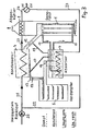
- a generator 1 (expeller) which is bi-heated directly by means of a burner, the exhaust gas cooler 2 integrated with this, a hot water-cooled condenser 3, a hot water-cooled absorber 4 and an evaporator 5 with direct heat coupling from a low-temperature heat source, namely, for example the outside air.
- Generator 1 and absorber 4 form a communicatively connected system which is filled with a suitable working fluid solution (refrigerant and solvent, eg CH 3 0H / H 2 0-LiBr), the majority of the working fluid solution being accommodated in the absorber 4.
- a suitable working fluid solution eg CH 3 0H / H 2 0-LiBr
- the generator 1 is equipped with a burner, e.g. B. an oil or gas burner, heated directly. Its heat exchanger, through which the working fluid flows from bottom to top, has a small volume, which is why the evaporation of the more volatile component (s) (refrigerant) starts after a very short time, for example after half a minute.
- the communicating connection of the heat exchanger of the generator 1 with the absorber 4 takes place via a low-lying connection line 10 for the incoming rich solution and an elevated connection line 11 for the outgoing poor solution.
- the formation of vapor bubbles in the vertical boiler tubes of the heat exchanger of generator 1, which is thus designed as a thermosiphon, sets in motion a natural circulation of the refrigerant-rich solution between generator 1 and absorber 4, which ensures a sufficiently high heat and material exchange in generator 1.
- the refrigerant vapor itself is deposited in the higher condenser 3 and for later evaporation stocked or throttled passed into the evaporator 5.
- the upper end of the heat exchanger of the generator 1 is connected to the vapor space of the condenser 3 by a connecting line 12.
- the condensation heat released when the refrigerant vapor is precipitated is given off as useful heat to a heating water flow which is to be heated and returned from a heating system and which then passes through the exhaust gas cooler 2.
- the exhaust gas cooler which is arranged in the upper part of the generator, uses the remaining exhaust gas heat that has not been transferred to the heat exchanger of the generator 1 up to almost the useful temperature.
- the liquefied refrigerant is first stored in the lower part of the condenser 3, in a refrigerant store or directly in the evaporator 5 for later evaporation.
- the condenser 3 is connected to the heat exchanger of the evaporator 5 through a condensate line 13 with a built-in shut-off valve 14.
- the vapor space of the heat exchanger of the evaporator 5 is connected to a connecting line 15 with a built-in one-way valve 16 with an overhead steam connection of the absorber 4.
- the one-way valve 16 can be a non-return valve which only allows the steam to pass from the evaporator 5 to the absorber 4 and also prevents the working agent solution from overflowing from the absorber 4 into the evaporator 5.
- the absorber 4 is connected to the lower part of the condenser 3 by means of a connecting line 17 in order to allow condensate to pass directly from the condenser 3 into the absorber 4 in direct or continuous heating mode, that is to say when the condensate store or evaporator is completely full.
- the return water flowing back from a heating system can be conveyed with the usual heating water pump 20 via a line 21 to the heat exchanger of the condenser 3 and via a line 22 to the heat exchanger of the absorber 4.
- the heating water emerging from the condenser 3 passes via a line 23 to the exhaust gas cooler 2 and a line 24 to a changeover valve 25 and, in the position shown in FIG. 1, into the heating water supply line 26.
- the absorber mode which follows at intervals (FIG. 2), after the changeover valve 25 has been switched over, the heating water now emerging from the absorber 4 passes via a line 27 directly to the changeover valve 25 and, in the position shown in FIG. 2, into the flow line 26.
- the one-way valve 14 in the line 13 between the condenser 3 and the evaporator 5, which can be designed as a float valve, ensures that the refrigerant reservoir of the condenser is filled to the maximum permissible level 3 or the evaporator that the condensate still accumulating in the condenser 3 runs back directly into the absorber 4.
- the working fluid solution serves as a pure heat transfer fluid and continuous heating operation (boiler operation), as shown in FIG. 3, with the maximum nominal heating output is possible.
- the generator-absorption heat pump heating system which could also be called a boiler with a periodically acting absorber part, is therefore a monovalent heating system that covers the maximum heating requirements of the building without any additional heating device.
- the generator operation is stopped, which means that the burner is switched off when the rising flow or return temperature of the heating system signals that there is no further heat requirement. This can be done with a simple heating water thermostat or with a temperature sensor in the solution.
- the generator mode automatically switches to the continuous heating mode according to FIG. 3, which can be continued for as long as desired. If heat demand is signaled again after the burner has been switched off, the absorber operation is initiated automatically by reversing the changeover valve 25, because the solution temperature now drops due to the heat being removed by the heating water and the solution thus becomes absorbent and the absorption process can therefore begin.
- absorber operation While there is a high pressure level of the working fluid solution in generator and continuous heating operation, absorber operation, as shown in FIG. 2, and into which the system can pass after the burner has been switched off, is characterized by low pressure.
- the changeover valve 25 By switching the changeover valve 25, the heating water flow from the condenser 3 and exhaust gas cooler 2 is directed to the heat exchanger of the absorber 4 and thereby the vapor pressure of the solvent is reduced by heat extraction and associated cooling below the vapor pressure of the refrigerant (mixture) in the evaporator, so that evaporation the same is made possible at low temperatures.
- a device for example a fan, for transporting the low-temperature heat carrier, that is to say the air, is put into operation.
- the fan can be switched on via a temperature difference sensor.
- the cold steam from the evaporator 5 passes the one-way valve 16 in the form of a non-return flap in the connecting line 15 to the absorber 4 and is absorbed in it above the useful temperature level, see FIG. 2.
- Outside air, exhaust air, groundwater, running water, absorber roof, etc. come as a low-temperature heat source. in question.
- the heat of absorption generated during absorption is now fed to the heating system via the heat exchanger of the absorber 4, which is now flowed through by the heating water.
- absorber 4 itself Numerous measures can be provided to optimize the heat and mass transfer and to use the solvent until it reaches its initial concentration.
- the minimum required temperature increase in absorber or heat pump operation can be set by the refrigerant concentration of the filled solution within the limits specified by the material system.
- the storage of a certain amount of refrigerant can be achieved by evaporation at sliding, ie dependent on the necessary temperature increase, absorber temperature. In this way, for each difference between the outside temperature and the heating water temperature, maximum utilization of the degassing width of the working material system and thus maximum use of low temperature heat are possible.
- refrigerant mixtures e.g. water and methanol
- the lower-boiling component remains partially stored at low outside temperatures, e.g. 0 ° C, while at higher outside temperatures, e.g. 12 ° C, their advantageous thermodynamic properties come into play.
- the continuous heating operation of the heating system with nominal heating output described with reference to Fig. 3 is possible if the condensate accumulated during the expulsion is returned directly to the absorber 4 .
- the working fluid solution which serves as heat transfer fluid in this operating phase, gives off the heating energy via the condenser 3 to the heating water.
- This periodically acting absorption heat pump thus represents a full-fledged heating system, which can provide both the base load and the peak load of the heating demand.
- the thermostat switches the burner out of operation again.
- the heating water flow is then switched over by means of the switching valve 25 to the heat exchanger of the absorber 4, when a renewed heat requirement is reported by falling below the predetermined heating water temperature.
- the absorption phase can be continued until the temperature of the heating water is no longer sufficient and the heating water temperature drops below a predetermined low heating water temperature, triggering the burner to start again.
- the heating power of the system is continuously regulated via the ratio of the burner runtime (generator operating time) to the absorber operating time.
- this results in particularly good heat conditions in part-load operation, because with increasing outside temperatures, the possible absorption of refrigerant vapor in the working fluid solution increases.
- the centerpiece of the directly heated generator 1 is a vertically arranged, cross-finned finned tube bundle, the finned tubes of which end in the lower part in an inlet distributor which is located in the immediate vicinity of the heating device (gas burner, oil burner or the like).
- the pipes open into a vapor-liquid separator, which has the task of separating the boiled-out solution from the refrigerant that is drawn off.
- a special, asymmetrical arrangement of baffles between the finned tubes ensures that the hot fuel gases are evenly applied to the tubes up to their upper end, so that the exhaust gas, already largely cooled, leaves the generator or expeller.
- the head of the generator is additionally designed as an exhaust gas cooler 2, so that the fuel can be used up to the calorific value.
- the vertical arrangement of the pipes with the horizontal guidance of the fuel gases along the fins, together with the solution delivery in the pipes caused by the vapor bubbles, ensures highly efficient heat or material exchange.
- the tubes are roughened on the inside to promote the formation of vapor bubbles.
- the absorber 4 is designed as a bubble absorber, ie the refrigerant vapor is introduced into the absorbent solution in such a way that thorough mixing thereof is achieved and concentration differences in this apparatus remain small during the absorption phase.
- Further measures to improve the heat and material exchange are the use of a tube bundle heat exchanger, which is profiled, for example, by milling, in order to achieve an increase in surface area, weight savings and the generation of turbulence in the solution, the installation of a circulation device with the aid of which spraying solution is collected and at the bottom of the Container again is fed, so that a natural circulation of the solution is guaranteed even in absorber operation.
- This arrangement prevents mixing of the solution in the generator phase, so that a largely constant degassing width can be achieved on the generator 1 during the entire expulsion time.
- Another advantage is that only a small amount of solution has to be heated for a short operation of the generator 1.
- the condenser 3 is designed as a spiral tube condenser, a drainage channel for the condensate being provided at the bottom of the cylindrical jacket.
- the apparatus itself is installed in such a way that the condensate drainage is made possible by gravity.
- the outside air evaporator 5 can be a flooded finned tube bundle (refrigerant in the tubes), in which a special distributor device ensures that the condensate is applied evenly to all tubes. This is achieved with the help of a distributor trough with overflow hole attached to the side of each finned tube row, which doses the amount of refrigerant per row.
- the container wall, on which the steam outlet openings of the pipes converge, is also inclined towards the vertical so that refrigerant from the upper rows, which splashes over during evaporation, flows back to the lower rows.
- the evaporator can also be operated as a dry evaporator if the supply line between a condensate store 3 and evaporator 5 is equipped with a distribution device for the finned tubes and an automatic control element for metering the required amount of refrigerant.
- the connecting line 15 between the evaporator 5 and the absorber 4 is equipped with an independently acting non-return valve 16, which has the task of preventing the condensation of refrigerant vapor in the evaporator during generator operation and also of avoiding an overflow of solution into the evaporator.
- the steam line 12 between the generator (expeller) 1 and the condenser 2 is kinked several times in order to avoid over-splashing of solution into the condenser 3 during violent generator operation.
Claims (12)
que l'eau de chauffage est fournie seulement au condenseur, s'il s'agit de l'apport de chaleur de haute température, et qu'elle est fournie seulement à l'absorbeur, s'il s'agit de l'apport de chaleur de basse température; en ce que, si la température de l'eau de chauffage de retour ou d'aller reste en-dessous d'une température de seuil inférieure, chaque fois, et d'une façon alternée, l'alimentation de la chaleur de haute ou de basse température est mise en route et est de nouveau arrêtée chaque fois que la température de seuil supérieur est excédée ou que la température de seuil inférieur n'est pas atteinte; et en ce qu'au moment du passage entre l'alimentation de chaleur de haute température et l'alimentation de chaleur de basse température, l'apport de l'agent frigorifique à partir de l'évaporateur vers l'absorbeur et à partir du condenseur vers l'évaporateur se réalise par l'intermédiaire de soupapes à une voie à commande automatique.
Priority Applications (1)
| Application Number | Priority Date | Filing Date | Title |
|---|---|---|---|
| AT85101699T ATE58225T1 (de) | 1984-02-17 | 1985-02-15 | Verfahren zum betreiben einer generatorabsorptionsw|rmepumpen-heizanlage fuer die raumheizung, warmwasserbereitung und dergl. und generator-absorptionswaermepumpen-heizanlage. |
Applications Claiming Priority (2)
| Application Number | Priority Date | Filing Date | Title |
|---|---|---|---|
| DE3405800 | 1984-02-17 | ||
| DE3405800A DE3405800C2 (de) | 1984-02-17 | 1984-02-17 | Verfahren zum Betreiben einer Generator-Absorptionswärmepumpen-Heizanlage für die Raumheizung und/oder Warmwasserbereitung und Generator-Absorptionswärmepumpen-Heizanlage |
Publications (3)
| Publication Number | Publication Date |
|---|---|
| EP0152931A2 EP0152931A2 (fr) | 1985-08-28 |
| EP0152931A3 EP0152931A3 (en) | 1987-05-20 |
| EP0152931B1 true EP0152931B1 (fr) | 1990-11-07 |
Family
ID=6228071
Family Applications (1)
| Application Number | Title | Priority Date | Filing Date |
|---|---|---|---|
| EP85101699A Expired - Lifetime EP0152931B1 (fr) | 1984-02-17 | 1985-02-15 | Procédé pour actionner une installation de chauffage à générateur-pompe de chaleur d'absorption pour le chauffage des locaux, la préparation d'eau chaude et pareil et installation de chauffage générateur-pompe de chaleur d'absorption |
Country Status (3)
| Country | Link |
|---|---|
| EP (1) | EP0152931B1 (fr) |
| AT (1) | ATE58225T1 (fr) |
| DE (2) | DE3405800C2 (fr) |
Families Citing this family (7)
| Publication number | Priority date | Publication date | Assignee | Title |
|---|---|---|---|---|
| ITVR940028A1 (it) * | 1994-03-21 | 1995-09-22 | Alessandro Beschi | Macchina frigo-termica ad assorbimento. |
| DE10154032B4 (de) * | 2001-11-02 | 2005-06-23 | Bbt Thermotechnik Gmbh | Diffusionsabsorptionsanlage |
| JP5190286B2 (ja) * | 2008-03-27 | 2013-04-24 | 本田技研工業株式会社 | ボイラー付吸収式ヒートポンプユニット |
| JP2012513008A (ja) | 2008-12-19 | 2012-06-07 | インベンソール ゲーエムベーハー | 収着機(SorptionMachines)における再冷却用体積流を分流する減圧要素 |
| DE102013222658A1 (de) * | 2013-11-07 | 2015-05-07 | Robert Bosch Gmbh | Absorptionswärmepumpe |
| IT201800007258A1 (it) * | 2018-07-17 | 2020-01-17 | Macchina di riscaldamento ad attivazione termica | |
| EP3842710A1 (fr) | 2019-12-23 | 2021-06-30 | Technische Universität Berlin | Procédé de fonctionnement d'une installation de sorption et installation de sorption |
Family Cites Families (9)
| Publication number | Priority date | Publication date | Assignee | Title |
|---|---|---|---|---|
| DE427278C (de) * | 1922-06-17 | 1926-03-29 | Siemens Schuckertwerke G M B H | Absorptionsmaschine |
| DE842352C (de) * | 1945-06-13 | 1952-06-26 | Electrolux Ab | Absorptionskaelteapparat |
| DE2748415C2 (de) * | 1977-10-28 | 1986-10-09 | Naamloze Vennootschap Nederlandse Gasunie, Groningen | Heizverfahren und bimodales Heizsystem zum Heizen von Gebäuden |
| DE2758773C2 (de) * | 1977-12-29 | 1981-12-17 | Ask August Schneider Gmbh & Co Kg, 8650 Kulmbach | Bivalente Heizanlage |
| DE2938203A1 (de) * | 1979-09-21 | 1981-04-02 | Knoche, Karl-Friedrich, Prof. Dr.-Ing., 5100 Aachen | Verfahren und vorrichtung zur nutzung von bei niedriger temperatur aufgenommener waerme |
| DE3140003C2 (de) * | 1981-10-08 | 1984-07-05 | Buderus Ag, 6330 Wetzlar | Heizungsanlage |
| DE3149005A1 (de) * | 1981-12-10 | 1983-06-16 | Buderus Ag, 6330 Wetzlar | Verfahren und vorrichtung zum betreiben einer monovalent alternativen absorptionsheizanlage |
| DE3200436A1 (de) * | 1982-01-09 | 1983-07-21 | Buderus Ag, 6330 Wetzlar | Verfahren zum betreiben einer absorptionswaermepumpe und waermepumpe zur druchfuehrung des verfahrens |
| DE3204288A1 (de) * | 1982-02-06 | 1983-08-11 | Joh. Vaillant Gmbh U. Co, 5630 Remscheid | Sorptionswaermepumpe |
-
1984
- 1984-02-17 DE DE3405800A patent/DE3405800C2/de not_active Expired
-
1985
- 1985-02-15 AT AT85101699T patent/ATE58225T1/de not_active IP Right Cessation
- 1985-02-15 DE DE8585101699T patent/DE3580377D1/de not_active Expired - Lifetime
- 1985-02-15 EP EP85101699A patent/EP0152931B1/fr not_active Expired - Lifetime
Also Published As
| Publication number | Publication date |
|---|---|
| DE3405800C2 (de) | 1986-11-20 |
| ATE58225T1 (de) | 1990-11-15 |
| DE3580377D1 (de) | 1990-12-13 |
| DE3405800A1 (de) | 1985-08-22 |
| EP0152931A3 (en) | 1987-05-20 |
| EP0152931A2 (fr) | 1985-08-28 |
Similar Documents
| Publication | Publication Date | Title |
|---|---|---|
| DE2754626C2 (de) | Mit einer Energiequelle relativ niedriger Temperatur, insbesondere Solarenergie, arbeitende Kälteanlage | |
| DE3706072C2 (fr) | ||
| EP0010551A1 (fr) | Système de pompe à chaleur à absorption | |
| DE3007256A1 (de) | Zentralheizungs- und/oder warmwassererzeugungsanlage | |
| DE3233649C2 (de) | Absorptionskühl- und -heizsystem | |
| DE2131793A1 (de) | Verfahren und Anlage zur Schaffung und Erhaltung angenehmer Aufenthaltsbedingungen in Gebaeuderaeumen | |
| DE2457577C3 (de) | Absorptions-Kälteerzeugungsanlage | |
| EP0152931B1 (fr) | Procédé pour actionner une installation de chauffage à générateur-pompe de chaleur d'absorption pour le chauffage des locaux, la préparation d'eau chaude et pareil et installation de chauffage générateur-pompe de chaleur d'absorption | |
| DE2937025A1 (de) | Vorrichtung zur abfuehrung von waerme aus abdampf | |
| WO2006018216A1 (fr) | Machine frigorifique a absorption | |
| DE3106716A1 (de) | Zentralheizungs- und/oder warmwassererzeugungs-anlage | |
| DE1751333B2 (de) | Absorptions-kaelteanlage und verfahren zu ihrem betrieb | |
| CH359821A (de) | Verfahren zum Pumpen von Wärme von einem tieferen auf ein höheres Temperaturniveau | |
| DE2457578C3 (de) | Absorptions-Kälteerzeugungsanlage | |
| EP0091095B1 (fr) | Installation de chauffage par accumulation contenant un réservoir à sorption | |
| DE60109831T2 (de) | Absorptionskältegerät | |
| AT504399B1 (de) | Absorptionskältemaschine | |
| DE3020693C2 (de) | Absorptionskälteanlage | |
| DE3105796A1 (de) | "waermepumpe" | |
| DE3037777C2 (de) | Verfahren zur Erzeugung elektrischer Energie aus Wärme | |
| DE1211229B (de) | Anlage zum Erzeugen von Kaelte oder Waerme mit einer Absorptionskaeltemaschine | |
| DE938848C (de) | Absorptionskaeltemaschine | |
| DE3345061A1 (de) | Verfahren zur energierueckgewinnung aus einem waermespeichermedium, das einen kristallinen feststoff in form eines stoechiometrischen hydrats bilden kann, sowie unter verwendung dieses verfahrens arbeitender energiespeicher und hiermit versehenes heizsystem, kuehlsystem und energietransformationssystem | |
| DE10219262B4 (de) | Absorptionskälteverfahren für Temperaturen unter 0 °C ohne druckausgleichendem Gas | |
| EP0330198B1 (fr) | Echangeur de chaleur en tant qu'évaporateur à injection pour une machine frigorifique |
Legal Events
| Date | Code | Title | Description |
|---|---|---|---|
| PUAI | Public reference made under article 153(3) epc to a published international application that has entered the european phase |
Free format text: ORIGINAL CODE: 0009012 |
|
| AK | Designated contracting states |
Designated state(s): AT BE CH DE FR GB IT LI NL |
|
| RIN1 | Information on inventor provided before grant (corrected) |
Inventor name: GRABENHENRICH, HEINZ-BERND Inventor name: STEHMEIER, DIETER Inventor name: KNOCHE, KARL FRIEDRICH, DR.-ING. PROF. |
|
| PUAL | Search report despatched |
Free format text: ORIGINAL CODE: 0009013 |
|
| AK | Designated contracting states |
Kind code of ref document: A3 Designated state(s): AT BE CH DE FR GB IT LI NL |
|
| 17P | Request for examination filed |
Effective date: 19871119 |
|
| 17Q | First examination report despatched |
Effective date: 19880729 |
|
| GRAA | (expected) grant |
Free format text: ORIGINAL CODE: 0009210 |
|
| AK | Designated contracting states |
Kind code of ref document: B1 Designated state(s): AT BE CH DE FR GB IT LI NL |
|
| PG25 | Lapsed in a contracting state [announced via postgrant information from national office to epo] |
Ref country code: IT Free format text: LAPSE BECAUSE OF FAILURE TO SUBMIT A TRANSLATION OF THE DESCRIPTION OR TO PAY THE FEE WITHIN THE PRESCRIBED TIME-LIMIT;WARNING: LAPSES OF ITALIAN PATENTS WITH EFFECTIVE DATE BEFORE 2007 MAY HAVE OCCURRED AT ANY TIME BEFORE 2007. THE CORRECT EFFECTIVE DATE MAY BE DIFFERENT FROM THE ONE RECORDED. Effective date: 19901107 Ref country code: GB Effective date: 19901107 |
|
| REF | Corresponds to: |
Ref document number: 58225 Country of ref document: AT Date of ref document: 19901115 Kind code of ref document: T |
|
| REF | Corresponds to: |
Ref document number: 3580377 Country of ref document: DE Date of ref document: 19901213 |
|
| PGFP | Annual fee paid to national office [announced via postgrant information from national office to epo] |
Ref country code: FR Payment date: 19910118 Year of fee payment: 7 |
|
| PGFP | Annual fee paid to national office [announced via postgrant information from national office to epo] |
Ref country code: AT Payment date: 19910124 Year of fee payment: 7 |
|
| PGFP | Annual fee paid to national office [announced via postgrant information from national office to epo] |
Ref country code: CH Payment date: 19910125 Year of fee payment: 7 |
|
| PGFP | Annual fee paid to national office [announced via postgrant information from national office to epo] |
Ref country code: NL Payment date: 19910228 Year of fee payment: 7 |
|
| PGFP | Annual fee paid to national office [announced via postgrant information from national office to epo] |
Ref country code: BE Payment date: 19910305 Year of fee payment: 7 |
|
| ET | Fr: translation filed | ||
| GBV | Gb: ep patent (uk) treated as always having been void in accordance with gb section 77(7)/1977 [no translation filed] | ||
| PLBE | No opposition filed within time limit |
Free format text: ORIGINAL CODE: 0009261 |
|
| STAA | Information on the status of an ep patent application or granted ep patent |
Free format text: STATUS: NO OPPOSITION FILED WITHIN TIME LIMIT |
|
| 26N | No opposition filed | ||
| PG25 | Lapsed in a contracting state [announced via postgrant information from national office to epo] |
Ref country code: AT Effective date: 19920215 |
|
| PG25 | Lapsed in a contracting state [announced via postgrant information from national office to epo] |
Ref country code: BE Effective date: 19920228 |
|
| PG25 | Lapsed in a contracting state [announced via postgrant information from national office to epo] |
Ref country code: LI Effective date: 19920229 Ref country code: CH Effective date: 19920229 |
|
| PGFP | Annual fee paid to national office [announced via postgrant information from national office to epo] |
Ref country code: DE Payment date: 19920430 Year of fee payment: 8 |
|
| BERE | Be: lapsed |
Owner name: KNOCHE KARL-FRIEDRICH Effective date: 19920228 |
|
| PG25 | Lapsed in a contracting state [announced via postgrant information from national office to epo] |
Ref country code: NL Effective date: 19920901 |
|
| NLV4 | Nl: lapsed or anulled due to non-payment of the annual fee | ||
| PG25 | Lapsed in a contracting state [announced via postgrant information from national office to epo] |
Ref country code: FR Effective date: 19921030 |
|
| REG | Reference to a national code |
Ref country code: CH Ref legal event code: PL |
|
| REG | Reference to a national code |
Ref country code: FR Ref legal event code: ST |
|
| PG25 | Lapsed in a contracting state [announced via postgrant information from national office to epo] |
Ref country code: DE Effective date: 19931103 |