EP0152149B1 - Capteur optique de pression - Google Patents
Capteur optique de pression Download PDFInfo
- Publication number
- EP0152149B1 EP0152149B1 EP85200162A EP85200162A EP0152149B1 EP 0152149 B1 EP0152149 B1 EP 0152149B1 EP 85200162 A EP85200162 A EP 85200162A EP 85200162 A EP85200162 A EP 85200162A EP 0152149 B1 EP0152149 B1 EP 0152149B1
- Authority
- EP
- European Patent Office
- Prior art keywords
- pressure sensor
- pressure measurement
- pressure
- optical
- measurement chambers
- Prior art date
- Legal status (The legal status is an assumption and is not a legal conclusion. Google has not performed a legal analysis and makes no representation as to the accuracy of the status listed.)
- Expired
Links
Images
Classifications
-
- G—PHYSICS
- G01—MEASURING; TESTING
- G01L—MEASURING FORCE, STRESS, TORQUE, WORK, MECHANICAL POWER, MECHANICAL EFFICIENCY, OR FLUID PRESSURE
- G01L11/00—Measuring steady or quasi-steady pressure of a fluid or a fluent solid material by means not provided for in group G01L7/00 or G01L9/00
- G01L11/02—Measuring steady or quasi-steady pressure of a fluid or a fluent solid material by means not provided for in group G01L7/00 or G01L9/00 by optical means
Definitions
- the invention relates to an optical pressure sensor, consisting of a translucent body, which is connected to a pressure measuring chamber with an inlet opening for a pressurized liquid or gaseous medium and which is irradiated by polarized light, and from behind in the beam direction of the light the body arranged analyzer, which filters linearly polarized light from the light with a pressure-dependent polarization state with a strength that changes with the pressure in the pressure measuring chamber.
- Optical pressure sensors are used to record pressures or differential pressures of explosive liquids and gases, since optical pressure sensors are only connected to the evaluation circuit via optical fibers and are therefore free of electrical voltages that can cause dangerous sparking.
- an optical pressure sensor with a block-shaped, translucent body which is irradiated by polarized light and on which the pressure to be detected acts. If the pressure of a liquid or gaseous medium is to be recorded, it is necessary to pass the gas or liquid into a bellows which presses on the translucent body with a force corresponding to the pressure of the medium. As a result, the polarization state of the light radiating through the body is changed such that an analyzer arranged behind the body in the beam direction of the light filters out linearly polarized light with a strength corresponding to the magnitude of the liquid or gas pressure from the light with a pressure-dependent polarization state.
- the bellows and the translucent body are arranged in a chamber that serves as a holder for the bellows and the translucent body.
- the bellows In order to produce a defined and homogeneous distribution of stress in the translucent body, the bellows must be provided with a flat bottom and must be constructed in such a way that the liquid or gas pressure is directed along an axis perpendicular to the surface of the fastening chamber, so that the bellows in the direction the main voltage axis acts on the translucent body.
- a very high level of precision is therefore required in the manufacture and in particular in the adjustment of the known sensor, so that the sensor operates without errors and achieves the sensitivity required for measuring the liquid pressure.
- the object of the present invention is to provide a simply constructed, sensitive pressure sensor which precisely detects the pressure of a gas or a liquid and whose sensitivity can be varied within wide limits.
- the internal stresses in the translucent body change with the pressure of the liquid or gaseous medium introduced into the pressure measuring chamber.
- the liquid or gas pressure can be precisely determined by analyzing the polarization state of the polarized light which is already variable through very small internal voltages.
- the sensitivity of the pressure sensor can be changed within wide limits by changing the diameter and the shape of the pressure measuring chamber.
- the body In order to be able to measure the difference between two different gas or liquid pressures, it is advantageous for the body to have four pressure measuring chambers, which are distributed uniformly over its circumference and are opposed to one another in pairs, each with an inlet opening, different pressures being supplied to the two pressure measuring chamber pairs.
- the four pressure measuring chambers are designed as outwardly sealed slots, which face each other in pairs with their longitudinal walls, the area over which the gas or liquid presses on the area of the body which is illuminated by light is very large, as a result of which the pressure sensor is very sensitive reacts to gas or liquid pressures and in particular can measure small pressure differences with a high proportion of constant pressure without errors.
- slot-like pressure measuring chambers which are of straight design, can be milled out of the translucent body in a particularly simple manner.
- the four pressure measuring chambers can be designed as round bores that lie on a common radius and are sealed off from the outside.
- the manufacture of the pressure sensor is simplified if the pressure measuring chambers are incorporated as through holes in the body, on which sealing plates are attached on both sides in the area of the pressure measuring chambers.
- a pressure sensor that is easy to manufacture is obtained if the sealing plates are made of metal and are screwed together.
- the polarization state of the light is not influenced by internal stresses of the body caused by the sealing plates, since the internal stresses are parallel to the direction of the light.
- the translucent body consists of a round disc and are the Sealing plates are ring-shaped.
- Such pressure sensors are compact and easy to manufacture.
- the body has additional cutouts between the pressure measuring chambers.
- the internal stresses are concentrated on the area of the translucent body which is irradiated by light, which increases the sensitivity of the pressure sensor.
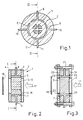
- the translucent body 2 shown in section in FIG. 1 contains four pressure measuring chambers 5 to 8 designed as part-circular slits.
- the walls of slits 6, 8 and 5, 7 lying opposite one another can be arranged flat and parallel to one another.
- the slots formed as through holes are sealed to the outside by two sealing plates 3 and 4 applied to the two end faces of the body 2.
- the sealing plates 3 and 4 can be made of the same material as the translucent body 2. They are glued to the end faces of the body 2, for example.
- Each pressure measuring chamber 5 to 8 is provided with its own inlet opening 9 to 12.
- a pressurized liquid or gaseous medium is supplied to the pressure measuring chambers 5 to 8 via these inlet openings 9 to 12.
- the pressure measuring chambers 5 to 8 are evenly distributed over the circumference of the body 2 and lie on a common radius.
- the body 2 can be provided with fewer than four pressure measuring chambers, for example with only one pressure measuring chamber or also with more than four pressure measuring chambers.
- the translucent body 2 is designed as a round disk and consists of quartz glass, glass ceramic or titanium silicate glass. It can have any other shape, for example the shape of a cube or a cuboid. If the body 2 has a diameter of 6 cm and a thickness of 3 cm, the pressure sensor 1 has a measuring range of approximately 1 to 10 bar without the additional recesses 13 to 16 to be described.
- the pressure measuring chambers 5 to 8 can also be designed as continuous, round bores with a diameter of, for example, 1 to 3 mm. Then the measuring range of the pressure sensor is approx. 10 to 500 bar. The measuring range of the pressure sensor can be varied within wide limits via the hole diameter and the distance between the holes.
- the sensitivity of the pressure sensor can be further increased by recesses 13 to 16 additionally machined into the body 2 between the pressure measuring chambers 5 to 8.
- the recesses 13 to 16 can, as shown in FIGS. 1 and 2, be formed as through holes. If the distance between the outer walls of the recesses 13 and 16 or 14 and 15 is approximately 25 mm, cross-shaped webs with a width of a few millimeters are formed between them, on which the internal stresses in the body 2 are concentrated. This enables a measuring range of approx. 10 mbar to 1 bar to be achieved.
- an analyzer 18 designed as a polarizer filters out linearly polarized light from the light 17, the strength of which is a measure of the pressure of the medium to be measured.
- the ring-shaped sealing plates 19 and 20 of the pressure sensor shown in FIG. 3 consist of metal and are connected to one another by means of screw bolts 21 and 22. Between the body 2 and the sealing plates 19 and 20 there are sealing rings 23 to 26 which seal the pressure measuring chambers 5 to 8 to the outside.
- the internal stresses caused by the sealing plates 19 and 20 in the body 2 lie parallel to the direction 17 of the light radiating through the body 2 and thus have no influence on the measurement result.
Landscapes
- Physics & Mathematics (AREA)
- General Physics & Mathematics (AREA)
- Measuring Fluid Pressure (AREA)
Claims (10)
Applications Claiming Priority (2)
| Application Number | Priority Date | Filing Date | Title |
|---|---|---|---|
| DE3405026 | 1984-02-13 | ||
| DE19843405026 DE3405026A1 (de) | 1984-02-13 | 1984-02-13 | Optischer drucksensor |
Publications (3)
| Publication Number | Publication Date |
|---|---|
| EP0152149A2 EP0152149A2 (fr) | 1985-08-21 |
| EP0152149A3 EP0152149A3 (en) | 1986-09-10 |
| EP0152149B1 true EP0152149B1 (fr) | 1989-05-10 |
Family
ID=6227544
Family Applications (1)
| Application Number | Title | Priority Date | Filing Date |
|---|---|---|---|
| EP85200162A Expired EP0152149B1 (fr) | 1984-02-13 | 1985-02-11 | Capteur optique de pression |
Country Status (4)
| Country | Link |
|---|---|
| US (1) | US4612810A (fr) |
| EP (1) | EP0152149B1 (fr) |
| JP (1) | JPS60187836A (fr) |
| DE (2) | DE3405026A1 (fr) |
Families Citing this family (18)
| Publication number | Priority date | Publication date | Assignee | Title |
|---|---|---|---|---|
| JPH01158326A (ja) * | 1987-09-11 | 1989-06-21 | Toshiba Corp | 温度測定装置 |
| EP0440790B1 (fr) * | 1987-09-11 | 1994-06-08 | Kabushiki Kaisha Toshiba | Appareil de mesure de temperature |
| US4805461A (en) * | 1987-10-02 | 1989-02-21 | Washington State University Research Foundation, Inc. | Transducer and systems for high speed measurement of shock loads |
| US4911015A (en) * | 1988-11-14 | 1990-03-27 | Asea Brown Boveri Inc. | Non-electrical monitoring of a physical condition |
| FR2642521B1 (fr) * | 1989-02-02 | 1993-01-22 | Schlumberger Ind Sa | Capteur optique de pression ainsi que procede et dispositif pour la realisation d'un tel capteur |
| US5187983A (en) * | 1991-09-04 | 1993-02-23 | Universite Du Quebec A Hull | Fiber-optic strain gauge manometer |
| DE19710499B4 (de) * | 1996-03-13 | 2008-02-21 | Berghof Laborprodukte Gmbh | Vorrichtung zur berührungslosen Druckmessung in einem Druckaufschlußgefäß |
| DE69931348D1 (de) | 1998-12-17 | 2006-06-22 | Chevron Usa Inc | Vorrichtung und verfahren zum schutz von optischen geräten unter rauhen betriebszuständen |
| US6766703B1 (en) | 1999-02-05 | 2004-07-27 | Sensor Dynamics Limited | Apparatus and method for enhancing remote sensor performance and utility |
| DE60125018T2 (de) | 2000-02-11 | 2007-06-28 | Rosemount Inc., Eden Prairie | Optischer druckaufnehmer |
| US6937394B2 (en) * | 2001-04-10 | 2005-08-30 | Carl Zeiss Semiconductor Manufacturing Technologies Ag | Device and method for changing the stress-induced birefringence and/or the thickness of an optical component |
| US6659976B2 (en) | 2001-04-16 | 2003-12-09 | Zevek, Inc. | Feeding set adaptor |
| US6523414B1 (en) * | 2001-04-16 | 2003-02-25 | Zevex, Inc. | Optical pressure monitoring system |
| US7561776B2 (en) * | 2005-11-29 | 2009-07-14 | Petrospec Engineering Ltd. | Method of preventing hydrogen darkening of optic fibre |
| US8486020B2 (en) | 2010-08-11 | 2013-07-16 | Zevex, Inc. | Pressure sensor and method of use |
| ES2766780T3 (es) | 2010-10-01 | 2020-06-15 | Zevex Inc | Sistema de monitorización de presión para bombas de infusión |
| US8752436B2 (en) | 2010-10-01 | 2014-06-17 | Zevex, Inc. | Pressure sensor seal and method of use |
| US9417103B2 (en) | 2011-09-20 | 2016-08-16 | Schlumberger Technology Corporation | Multiple spectrum channel, multiple sensor fiber optic monitoring system |
Family Cites Families (2)
| Publication number | Priority date | Publication date | Assignee | Title |
|---|---|---|---|---|
| GB1068014A (en) * | 1965-01-22 | 1967-05-10 | Ivor Hawkes | Improvements in or relating to pressure gauges |
| JPS57211523A (en) * | 1981-06-23 | 1982-12-25 | Tokai Rika Co Ltd | Pressure measuring device |
-
1984
- 1984-02-13 DE DE19843405026 patent/DE3405026A1/de not_active Withdrawn
-
1985
- 1985-02-11 DE DE8585200162T patent/DE3570126D1/de not_active Expired
- 1985-02-11 US US06/700,377 patent/US4612810A/en not_active Expired - Fee Related
- 1985-02-11 EP EP85200162A patent/EP0152149B1/fr not_active Expired
- 1985-02-12 JP JP60025087A patent/JPS60187836A/ja active Granted
Non-Patent Citations (1)
| Title |
|---|
| LASER UND OPTOELEKTRONIK, Band 15, Nr. 3, September 1983, Seiten 226-243, Stuttgart, DE; K. SPENNER et al.: "Faseroptische Multimode-Sensoren: eine Übersicht" * |
Also Published As
| Publication number | Publication date |
|---|---|
| DE3570126D1 (en) | 1989-06-15 |
| EP0152149A2 (fr) | 1985-08-21 |
| US4612810A (en) | 1986-09-23 |
| DE3405026A1 (de) | 1985-08-14 |
| JPS60187836A (ja) | 1985-09-25 |
| EP0152149A3 (en) | 1986-09-10 |
| JPH0528337B2 (fr) | 1993-04-26 |
Similar Documents
| Publication | Publication Date | Title |
|---|---|---|
| EP0152149B1 (fr) | Capteur optique de pression | |
| DE4042411C2 (de) | Kapazitiver Differenzdruckdetektor | |
| DE2052515B2 (de) | Kapazitiver Druckfühler | |
| DE3122438A1 (de) | Druckmessdose | |
| EP0111348B1 (fr) | Transducteur capacitif de pression différentielle | |
| DE2657119A1 (de) | Drucksensor fuer faseroptik | |
| DE2709834A1 (de) | Kapazitiver druckfuehler | |
| EP0759547A1 (fr) | Capteur de pression | |
| DE3713236C2 (fr) | ||
| DE102008033337A1 (de) | Druckmittler und Druckmessgerät mit einem solchen Druckmittler | |
| DE3233179C2 (fr) | ||
| EP0276889B1 (fr) | Capteur de pression pour charges de pression statiques avec corps en silicium | |
| DE69003763T2 (de) | Membran-Deformationsmessvorrichtung. | |
| EP1275951B1 (fr) | Capteur de pression et procédé de surveillance de son fonctionnement | |
| EP0410014A1 (fr) | Capteur de pression et procédé pour calibrer des capteurs de pression | |
| DE19617696C2 (de) | Mikromechanischer Druck- und Kraftsensor | |
| EP1591766A2 (fr) | Dispositif de mesure optique et capteur de force | |
| EP0126172B1 (fr) | Dispositif d'amortissement pour capteurs de force | |
| DE3928733A1 (de) | Manometer mit mehreren bourdon-roehrenspulen | |
| DE2263901B2 (de) | Meßumformer | |
| DE4207950C1 (en) | Capacitative differential pressure sensor - has two carrier plates of monocrystalline silicon@ with flat recesses etched to form measuring chamber by facing diaphragm plate of boron silicate glass | |
| DE3703241C1 (de) | Schwingquarz mit temperaturabhaengiger Resonanzfrequenz | |
| DE4411853A1 (de) | Optoakustischer Gassensor | |
| EP1505378A1 (fr) | Système de transmission de pression | |
| DE102014212766A1 (de) | Differenzdruckmessumformer mit einem Überlastschutzsystem |
Legal Events
| Date | Code | Title | Description |
|---|---|---|---|
| PUAI | Public reference made under article 153(3) epc to a published international application that has entered the european phase |
Free format text: ORIGINAL CODE: 0009012 |
|
| AK | Designated contracting states |
Designated state(s): DE FR GB |
|
| PUAL | Search report despatched |
Free format text: ORIGINAL CODE: 0009013 |
|
| AK | Designated contracting states |
Kind code of ref document: A3 Designated state(s): DE FR GB |
|
| 17P | Request for examination filed |
Effective date: 19870226 |
|
| RAP1 | Party data changed (applicant data changed or rights of an application transferred) |
Owner name: N.V. PHILIPS' GLOEILAMPENFABRIEKEN Owner name: PHILIPS PATENTVERWALTUNG GMBH |
|
| 17Q | First examination report despatched |
Effective date: 19880510 |
|
| GRAA | (expected) grant |
Free format text: ORIGINAL CODE: 0009210 |
|
| AK | Designated contracting states |
Kind code of ref document: B1 Designated state(s): DE FR GB |
|
| REF | Corresponds to: |
Ref document number: 3570126 Country of ref document: DE Date of ref document: 19890615 |
|
| ET | Fr: translation filed | ||
| GBT | Gb: translation of ep patent filed (gb section 77(6)(a)/1977) | ||
| PLBE | No opposition filed within time limit |
Free format text: ORIGINAL CODE: 0009261 |
|
| STAA | Information on the status of an ep patent application or granted ep patent |
Free format text: STATUS: NO OPPOSITION FILED WITHIN TIME LIMIT |
|
| 26N | No opposition filed | ||
| PGFP | Annual fee paid to national office [announced via postgrant information from national office to epo] |
Ref country code: GB Payment date: 19910201 Year of fee payment: 7 |
|
| PGFP | Annual fee paid to national office [announced via postgrant information from national office to epo] |
Ref country code: FR Payment date: 19910219 Year of fee payment: 7 |
|
| PGFP | Annual fee paid to national office [announced via postgrant information from national office to epo] |
Ref country code: DE Payment date: 19910424 Year of fee payment: 7 |
|
| PG25 | Lapsed in a contracting state [announced via postgrant information from national office to epo] |
Ref country code: GB Effective date: 19920211 |
|
| GBPC | Gb: european patent ceased through non-payment of renewal fee | ||
| PG25 | Lapsed in a contracting state [announced via postgrant information from national office to epo] |
Ref country code: FR Effective date: 19921030 |
|
| PG25 | Lapsed in a contracting state [announced via postgrant information from national office to epo] |
Ref country code: DE Effective date: 19921103 |
|
| REG | Reference to a national code |
Ref country code: FR Ref legal event code: ST |