EP0151641B1 - Laufkran - Google Patents
Laufkran Download PDFInfo
- Publication number
- EP0151641B1 EP0151641B1 EP83902448A EP83902448A EP0151641B1 EP 0151641 B1 EP0151641 B1 EP 0151641B1 EP 83902448 A EP83902448 A EP 83902448A EP 83902448 A EP83902448 A EP 83902448A EP 0151641 B1 EP0151641 B1 EP 0151641B1
- Authority
- EP
- European Patent Office
- Prior art keywords
- rail
- monorail
- carrier
- side face
- overhead travelling
- Prior art date
- Legal status (The legal status is an assumption and is not a legal conclusion. Google has not performed a legal analysis and makes no representation as to the accuracy of the status listed.)
- Expired
Links
- 239000000969 carrier Substances 0.000 claims abstract description 10
- 230000005540 biological transmission Effects 0.000 claims abstract description 6
- 229920003002 synthetic resin Polymers 0.000 claims abstract description 6
- 239000000057 synthetic resin Substances 0.000 claims abstract description 6
- 230000037431 insertion Effects 0.000 claims 1
- 238000003780 insertion Methods 0.000 claims 1
- 230000008878 coupling Effects 0.000 abstract 1
- 238000010168 coupling process Methods 0.000 abstract 1
- 238000005859 coupling reaction Methods 0.000 abstract 1
- 230000011664 signaling Effects 0.000 description 5
- 238000009413 insulation Methods 0.000 description 4
- 238000010276 construction Methods 0.000 description 3
- 230000000694 effects Effects 0.000 description 3
- 238000003754 machining Methods 0.000 description 3
- 238000004519 manufacturing process Methods 0.000 description 3
- 238000005553 drilling Methods 0.000 description 2
- 238000012423 maintenance Methods 0.000 description 2
- 230000002035 prolonged effect Effects 0.000 description 2
- 239000004677 Nylon Substances 0.000 description 1
- XAGFODPZIPBFFR-UHFFFAOYSA-N aluminium Chemical compound [Al] XAGFODPZIPBFFR-UHFFFAOYSA-N 0.000 description 1
- 229910052782 aluminium Inorganic materials 0.000 description 1
- 238000005452 bending Methods 0.000 description 1
- 230000015572 biosynthetic process Effects 0.000 description 1
- 230000006866 deterioration Effects 0.000 description 1
- 238000001125 extrusion Methods 0.000 description 1
- 239000004519 grease Substances 0.000 description 1
- 230000002452 interceptive effect Effects 0.000 description 1
- 238000005304 joining Methods 0.000 description 1
- 238000005461 lubrication Methods 0.000 description 1
- 239000000463 material Substances 0.000 description 1
- 238000000034 method Methods 0.000 description 1
- 229920001778 nylon Polymers 0.000 description 1
- 230000002093 peripheral effect Effects 0.000 description 1
- 238000011179 visual inspection Methods 0.000 description 1
Images


Classifications
-
- H—ELECTRICITY
- H01—ELECTRIC ELEMENTS
- H01R—ELECTRICALLY-CONDUCTIVE CONNECTIONS; STRUCTURAL ASSOCIATIONS OF A PLURALITY OF MUTUALLY-INSULATED ELECTRICAL CONNECTING ELEMENTS; COUPLING DEVICES; CURRENT COLLECTORS
- H01R41/00—Non-rotary current collectors for maintaining contact between moving and stationary parts of an electric circuit
-
- B—PERFORMING OPERATIONS; TRANSPORTING
- B66—HOISTING; LIFTING; HAULING
- B66C—CRANES; LOAD-ENGAGING ELEMENTS OR DEVICES FOR CRANES, CAPSTANS, WINCHES, OR TACKLES
- B66C11/00—Trolleys or crabs, e.g. operating above runways
- B66C11/02—Trolleys or crabs, e.g. operating above runways with operating gear or operator's cabin suspended, or laterally offset, from runway or track
- B66C11/04—Underhung trolleys
- B66C11/06—Underhung trolleys running on monorails
-
- B—PERFORMING OPERATIONS; TRANSPORTING
- B66—HOISTING; LIFTING; HAULING
- B66C—CRANES; LOAD-ENGAGING ELEMENTS OR DEVICES FOR CRANES, CAPSTANS, WINCHES, OR TACKLES
- B66C13/00—Other constructional features or details
- B66C13/12—Arrangements of means for transmitting pneumatic, hydraulic, or electric power to movable parts of devices
-
- B—PERFORMING OPERATIONS; TRANSPORTING
- B66—HOISTING; LIFTING; HAULING
- B66C—CRANES; LOAD-ENGAGING ELEMENTS OR DEVICES FOR CRANES, CAPSTANS, WINCHES, OR TACKLES
- B66C7/00—Runways, tracks or trackways for trolleys or cranes
Definitions
- the present invention relates to an overhead travelling conveyor adapted to travel on an I-shaped monorail. More particularly, it is concerned with an overhead travelling conveyor suitable for conveyance which may involve frequent starting and stopping, especially sudden stopping, and which is also suitable for a curved rail.
- Conventional overhead travelling conveyors have a structure in which right and left wheels of a carrier travel on a rail composed of a pair of channel members fixed to a support member and in which bus bars for supplying power to a running motor are disposed inside the rail.
- This structure ensures safety even in the use of bare bars, but since the wheel diameter is restricted to a relatively small diameter, it is necessary to increase the number of wheels when the conveyed load is large.
- a special quenched rail must be used with the result that the rail weight becomes larger.
- FR-A-2387 149 describes an I-shaped monorail, the upper flange surface of which is conversely curved to support the wheel of the carrier, which has a corresponding peripheral groove to fit over the rail.
- Guide wheels are positioned to engage the bottom flanges of the rail to provide lateral stability and receive lateral forces on the carrier wheel.
- the upper and lower flange surfaces form recesses on both sides of the monorail by virtue of their shape.
- an overhead travelling conveyor including a monorail which comprises
- a conveyance article holding means is supportd through a spherical bearing attached to the conveyance article holding means suspending portion of the load bar, so even if a lateral load is exerted on the conveyance article holding means and the conveyance article itself during travelling on a curved portion of the rail or during working, such load can be absorbed by the spherical bearing. Consequently, only vertical loads are imposed on the wheels and the guide rollers do not undergo a large lateral load, so that the rail is not subject to a torsional load nor are the load bar connecting pins subject to an excessive load.
- a notched portion of a size which permits the lower portion of the carrier to be removed sideways of the monorail is formed in part of the lower portion of the monorail of I-shaped section, and a rail piece corresponding to such notched portion is fixed detachably to the notched portion.
- a carrier 11 comprises a driving carrier 13 and a driven carrier 14 both adapted to travel on a rail 12 of I-shaped section and interconnected through a load bar 15. From the load bar 15 is suspended conveyance article holding means 16 such as an electrically operated chain block, hoist, or the like.
- the driving carrier 13 has a generally E-shaped frame 20 on the upper part of which is mounted a bearing portion 21 which supports an axle 23 of a cylindrical wheel 22 adapted to travel on the rail 12, the wheel 22 being formed of rubber or synthetic resin such as nylon.
- the wheel 22 being formed of rubber or synthetic resin such as nylon.
- an upper arm 24 and an intermediate arm 25 of the frame 20 respectively, on which are mounted vertical-axle guide rollers 26 and 27, respectively, adjacent to both sides of the rail 12, the guide rollers 26 and 27 being formed of rubber or synthetic resin.
- the guide rollers 27 prevent lateral swinging of the driving carrier 13. Therefore, only a single pair of right and left guide rollers 27 may be provided below the wheel 22.
- Both ends of a vertical pin 29 are inserted and fixed into holes respectively formed in the intermediate arm 25 and a lower arm of the frame 20 on a perpendicular which passes the center of the wheel 22, and one end of the load bar 15 is fitted on an intermediate portion of the pin 29 through a bushing.
- a running reduction motor 30 is attached to the back of the lower portion of the frame 20.
- the wheel axle 23 and the motor shaft are connected for power transmission through toothed belt wheels 31 and 32 and a toothed belt 33.
- the toothed belt 33 is kept tensioned by a roller 34 mounted on the frame 20.
- the driven carrier 14, as shown in Figs. 4 and 5, is similar to the driving carrier 13 and has an E-shaped frame 35, a cylindrical wheel 36, guide rollers 37 and 38 and a pin 39.
- the other end of the load bar 15 is fitted and supported on the pin 39 similarly to the case of the pin 29.
- the driven carrier is further provided with collector means for receiving power for the running motor 30 and the electrically operated chain block from trolley lines 40 and for transmitting and receiving control signals.
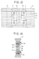
- a support structure for the trolley lines 40 in which many grooves 43 are formed in the outside of support means 41 and a notched concave 44 is formed between adjacent grooves 43 to form resilient deformable legs 45 at opposite sides of each groove 43, and a latch portion 46 projecting into the groove 43 is formed on the outer end of each leg 45.
- Each of the bus bars 40 comprises an extruded member having a generally square external form and a hollow portion 47. It is provided with a longitudinal opening 48 at one side of the hollow portion and with retaining portions 49 projecting on both sides of the opening 48. A side wall opposed to the opening 48 is slightly inwardly concaved to form a slightly concaved outer surface of the side wall which outer surface serves as a sliding contact surface 50, and projecting portions 51 are formed on both sides of the sliding contact surface 50.
- Each of the bus bars 40 has such a sectional shape.
- the bus bars 40 are each fitted into an insulation sheath 52 having a S-shaped section and held in place by projections 53 formed at both edges of the sheath 52.
- the assembly thus fabricated is press-fitted into the groove 43 and held in place by the latch portions 46.
- a connector fitting 54 which spans both trolley lines is inserted into the hollow portion 47 and a screw 55 is threadedly inserted through the opening 48 and is fastened so that the leading end of the screw is brought into pressure contact with the inner wall of the hollow portion 47, whereby both side portions of the connector 54 are forcedly contacted with the inner surfaces of the retaining portions 49.
- the upper three bus bars are power supply lines for the motor and the lower two are control signal lines for insulating a specific section from the other sections to effect starting or stopping of the carrier.
- the bus bars 40 are covered with the insulation sheath 52 as previously noted, and it is only a slight projection of the screw 55 that projects at the junction of trolley lines. Therefore, the bus bars 40 can be laid easily and compactly with a high accuracy in proximity to the web 18.
- tip end portions of upper and lower rail fixing members 42 of the bus bars supporting means 41 are inserted into concave portions formed between a side face of the web 18 and projections 17, then bolts 42a are threadedly fitted into threaded portions 42' formed in the rail fixing members 42 and tightened to let the leading ends of the bolts 42a come into pressure contact with the side face of the web 18 and the rail fixing members 42 into pressure contact with side faces of the projections 17, whereby the bus bars supporting means 41 is fixed to the rail 12.
- the bus bar supporting means 41 as shown in Fig. 7, is first disposed sideways on a side face of the rail web 18 and then turned to a predetermined position.
- Collector shoes 57 which are in sliding contact with the bus bar 40 are attached to an insulation plate 56 which is fixed by screws to the frame 35 of the driven carrier 14, as shown in Fig. 5. Since the driven carrier 14 scarcely undergoes a lateral vibration as previously noted, there may be used small-sized collector shoes 56 having only a limited range of movement, whereby a good current collecting effect can be attained.
- the I-shaped rail 12 is formed of aluminum or other material by extrusion.
- Recessed portions 18a for a rail connecting plate are formed along the longitudinal direction in both side faces of a web 18, and pressure-mounting projections 17 for the rail hanger means and for the power supplying and signalling bus bars supporting means are formed along the longitudinal direction of the side faces of the web 18 on the opposed faces of upper and lower flanges 12c which form a running surface 12a for the wheels of the monorail travelling conveyor and guide surfaces 12b for the guide rollers of the conveyor.
- Figs. 9 and 10 are a side view and a front sectional view, respectively, there is shown the rail 12 as suspended and fixed by rail hanger means 60. More specifically, a rail fixing member 61 provided at the tip end portion of the rail hanger means 60 which is fixed to the ceiling is brought into abutment with the outer surfaces of one projections 17 of the rail flanges 12c, then bolts 63 are each inserted through a bolt hole 62 of the rail fixing member 61 into a threaded portion 65 of a patch plate 64 which is partially fitted in the concave portions formed between the side face of the web 18 and the projections 17, and then tightened, whereby both side faces of the projections 17 of the rail flanges 12c are gripped by the rail fixing member 61 of the rail hanger means 60 and the patch plate 64 to thereby fix the rail 12 to the rail hanger means 60.
- the patch plate 64 is first sideways disposed on a side face of the web 18 and then turned to a predetermined position, as shown in Fig. 11.
- the numeral 76 denotes a mounting space for the connector fitting for connection of power supplying and signalling bus bars formed in each rail section. Since the drilling reference lines 18b are provided on the side faces of the web 18 along the longitudinal direction, it is very easy to machine the rail connecting bolt holes 74, etc.
- Both ends of the load bar 15 are supported by the pins 29 and 39 which are supported at the respective both ends by the frames 20 and 35, respectively, as previously noted.
- This mounting provides a highly strong resistance against the inertia force of the conveyance article induced at the time of sudden stopping and also against a bending moment applied to the pins 29 and 39 due to the conveyance load at a sloped portion of the rail.
- the hanger In the case of suspending a conveyance article by a hanger attached to the load bar 15, the hanger is supported by the load bar 15 through a ball bearing.
- the pins 29 and 39 act as both end-supported beams, so can maintain a sufficient strength even against a sharp curve, and the surface pressure of the guide rollers 27 and 38 is reduced remarkably and their life much prolonged.
- FIG. 14 is a sectional view of a principal portion for supporting the conveyance article holding means by a spherical bearing, in which the conveyance article holding means 16 such as a chain block or hoist is supported in a suspended state through a suspending connection pin 81 by a spherical bearing 80 which is attached to the conveyance article holding means suspending portion of the load bar 15.
- a notched portion 90 of a size which permits the lower portion of the carrier to move out therefrom sideways of the rail 12.
- a rail piece 91 corresponding to the notched portion 90 is fixed with bolts 93 to a mounting plate 92 which is fixed to one side of the web 18 in the position of the notched portion 90.
- the driving and driven carriers 13 and 14 when the driving and driven carriers 13 and 14 are to be detached from the rail 12, first the rail piece 91 is removed from the rail 12, then those driving and driven carriers after removal therefrom of the conveyance article holding means 16 such as an electrically operated chain block or hoist and the load bar 15 are each successively brought into the position of the notched portion 90 of the rail 12, and the carrier now located in that position is moved sideways, whereby the driving and driven carriers 13 and 14 can each be detached from the rail 12.
- the carriers 13 and 14 can be loaded onto the rail 12 in accordance with operations reverse to the operations just described.
Landscapes
- Engineering & Computer Science (AREA)
- Mechanical Engineering (AREA)
- Carriers, Traveling Bodies, And Overhead Traveling Cranes (AREA)
- Framework For Endless Conveyors (AREA)
- Professional, Industrial, Or Sporting Protective Garments (AREA)
- Catching Or Destruction (AREA)
- Holders For Apparel And Elements Relating To Apparel (AREA)
Claims (3)
Applications Claiming Priority (1)
| Application Number | Priority Date | Filing Date | Title |
|---|---|---|---|
| PCT/JP1983/000249 WO1985000579A1 (fr) | 1983-08-01 | 1983-08-01 | Pont roulant |
Publications (3)
| Publication Number | Publication Date |
|---|---|
| EP0151641A1 EP0151641A1 (de) | 1985-08-21 |
| EP0151641A4 EP0151641A4 (de) | 1985-12-11 |
| EP0151641B1 true EP0151641B1 (de) | 1988-10-12 |
Family
ID=13790026
Family Applications (1)
| Application Number | Title | Priority Date | Filing Date |
|---|---|---|---|
| EP83902448A Expired EP0151641B1 (de) | 1983-08-01 | 1983-08-01 | Laufkran |
Country Status (6)
| Country | Link |
|---|---|
| EP (1) | EP0151641B1 (de) |
| AU (1) | AU546736B2 (de) |
| DE (1) | DE3378205D1 (de) |
| FI (1) | FI78885C (de) |
| NO (1) | NO164163C (de) |
| WO (1) | WO1985000579A1 (de) |
Families Citing this family (18)
| Publication number | Priority date | Publication date | Assignee | Title |
|---|---|---|---|---|
| DE3533835C1 (de) * | 1985-09-23 | 1986-11-27 | Seiwert Stahl- und Apparatebau GmbH, 6638 Dillingen | Tragsystem für Elektro-Hängebahnen |
| DE3820953A1 (de) * | 1988-06-16 | 1989-12-28 | Mannesmann Ag | Einrichtung zum steuern eines krans |
| DE4436520C1 (de) * | 1994-10-13 | 1995-09-07 | Wampfler Gmbh | Wagen zum Aufhängen und Verfahren an einer Schiene |
| MY122280A (en) * | 1999-03-12 | 2006-04-29 | Daimler Chrysler Ag | Power rail and guidebeam assembly for a vehicle transportation system |
| GB0400955D0 (en) * | 2004-01-16 | 2004-02-18 | Insul 8 Ltd | A track system |
| CN102452609A (zh) * | 2010-10-21 | 2012-05-16 | 黄石市天畅输送机械有限公司 | 工字钢自行小车活动式取电装置 |
| CN103318056B (zh) * | 2012-03-19 | 2015-08-12 | 松下电器产业株式会社 | 滑接导线用托架 |
| JP2014191964A (ja) * | 2013-03-27 | 2014-10-06 | Panasonic Corp | 絶縁トロリー用接続装置 |
| JP6337528B2 (ja) * | 2014-03-10 | 2018-06-06 | 村田機械株式会社 | 走行車輪の劣化検出方法と検出システム、及び走行台車 |
| CN103910284B (zh) * | 2014-04-18 | 2016-02-17 | 黎志春 | 一种天车自动套链条装置 |
| CN208289934U (zh) * | 2017-12-20 | 2018-12-28 | 南京理工大学 | 一种巡检机器人用检测装置 |
| CN108190423A (zh) * | 2018-01-23 | 2018-06-22 | 北京首钢建设集团有限公司 | 皮带系统自动清料机 |
| CN110240064B (zh) * | 2019-06-28 | 2020-10-20 | 威马汽车科技集团有限公司 | 一种用于新能源汽车的氢电池模组 |
| CN110834899B (zh) * | 2019-11-21 | 2021-08-06 | 泉州台商投资区明云机械有限公司 | 一种轨道输送架 |
| CN116829491A (zh) * | 2020-12-28 | 2023-09-29 | 阿希尔·瓦伊什 | 新型负载运输系统 |
| CN113954699A (zh) * | 2021-11-30 | 2022-01-21 | 中铁二院工程集团有限责任公司 | 一种变截面汇流排的刚柔过渡系统 |
| KR102686458B1 (ko) * | 2024-01-30 | 2024-07-19 | 이영순 | 모노레일의 배터리 충전용 콜렉터 |
| CN119873617B (zh) * | 2025-03-24 | 2025-06-24 | 新乡职业技术学院 | 一种曲线运行式可转弯单轨吊 |
Family Cites Families (15)
| Publication number | Priority date | Publication date | Assignee | Title |
|---|---|---|---|---|
| FR1072538A (fr) * | 1952-12-18 | 1954-09-14 | Franc Et Sa | Voies suspendues et véhicules adaptés pour se déplacer sur ces voies pour les transports urbains |
| US3092039A (en) * | 1958-07-28 | 1963-06-04 | Gen Steel Ind Inc | Suspended railway systems |
| BE743833A (de) * | 1969-12-30 | 1970-05-28 | ||
| DE2236509C3 (de) * | 1972-07-25 | 1983-11-24 | Thyssen Aufzüge GmbH, 7303 Neuhausen | Laufkatze für Einschienen-Hängebahnen |
| DE2545907C3 (de) * | 1975-10-14 | 1983-11-17 | Mannesmann AG, 4000 Düsseldorf | Förderbahn mit an einer Schiene geführten Katze |
| FR2333090A1 (fr) * | 1975-11-27 | 1977-06-24 | Tourtellier Sa Ets | Dispositif d'ouverture d'un rail tubulaire de voie suspendue |
| FR2387149A1 (fr) * | 1977-04-15 | 1978-11-10 | Tourtellier Sa Ets | Dispositif de manutention en particulier voie suspendue |
| DE2728881C2 (de) * | 1977-06-27 | 1979-08-23 | Ralfs Gmbh, 7346 Wiesensteig | Fahrwagen für den einschienigen Transport von Gütern |
| US4171670A (en) * | 1977-09-22 | 1979-10-23 | H. Arnold Seed | Overhead rail transportation systems |
| GB2067490B (en) * | 1980-01-09 | 1983-10-05 | Carrier Drysys Ltd | Tracked conveyors driven by stepping motors |
| DE3019301C2 (de) * | 1980-05-21 | 1982-06-24 | R. Stahl Gmbh & Co, 7000 Stuttgart | Freitragende Laufschiene für Einschienen-Hängebahnen |
| DE3030929C2 (de) * | 1980-08-16 | 1983-01-05 | Mannesmann AG, 4000 Düsseldorf | Laufkatze |
| JPS57131687A (en) * | 1981-02-06 | 1982-08-14 | Tsubakimoto Chain Co | Overhead travelling conveyor |
| JPS5839953Y2 (ja) * | 1981-02-17 | 1983-09-08 | 株式会社椿本チエイン | モノレ−ル装置 |
| FR2508949A1 (fr) * | 1981-07-01 | 1983-01-07 | Tourtellier Sa Ets | Monorail |
-
1983
- 1983-08-01 EP EP83902448A patent/EP0151641B1/de not_active Expired
- 1983-08-01 DE DE8383902448T patent/DE3378205D1/de not_active Expired
- 1983-08-01 WO PCT/JP1983/000249 patent/WO1985000579A1/ja not_active Ceased
-
1984
- 1984-02-10 AU AU24441/84A patent/AU546736B2/en not_active Ceased
- 1984-11-12 NO NO84844507A patent/NO164163C/no unknown
- 1984-11-30 FI FI844735A patent/FI78885C/fi not_active IP Right Cessation
Also Published As
| Publication number | Publication date |
|---|---|
| EP0151641A4 (de) | 1985-12-11 |
| AU546736B2 (en) | 1985-09-19 |
| NO164163B (no) | 1990-05-28 |
| WO1985000579A1 (fr) | 1985-02-14 |
| EP0151641A1 (de) | 1985-08-21 |
| FI78885C (fi) | 1989-10-10 |
| AU2444184A (en) | 1985-02-07 |
| NO164163C (no) | 1990-09-05 |
| FI844735L (fi) | 1985-02-02 |
| DE3378205D1 (en) | 1988-11-17 |
| FI78885B (fi) | 1989-06-30 |
| NO844507L (no) | 1985-02-14 |
| FI844735A0 (fi) | 1984-11-30 |
Similar Documents
| Publication | Publication Date | Title |
|---|---|---|
| EP0151641B1 (de) | Laufkran | |
| US4480157A (en) | Overhead running carrier | |
| EP0088452A2 (de) | Materialtransportsystem | |
| US4172423A (en) | Tracked vehicle systems | |
| CZ307595A3 (en) | Rail segment for a conveyor system and the conveyor system per se | |
| GB2380175A (en) | Conveying apparatus with articulated carriers | |
| US6360671B1 (en) | Friction drive system trolley conveyor | |
| US5755495A (en) | Bearing for snowmobile track | |
| CA2010459C (en) | Electric overhead trolley system | |
| US2633226A (en) | Hook conveyer | |
| JP2909552B2 (ja) | 自己推進トロリおよび支持軌道構造体 | |
| JPH062558B2 (ja) | 電気式天井トロリコンベア | |
| KR890002370B1 (ko) | 천정 주행 반송 장치 | |
| US4405042A (en) | Combination enclosure/support for conveyor apparatus, and methods of constructing and utilizing same | |
| CN217597109U (zh) | 巡检机器人系统 | |
| CN215553648U (zh) | 一种履带链轨总成结构 | |
| JPH10109813A5 (de) | ||
| CN216071657U (zh) | 一种可双向交错连接的输送传递装置 | |
| CN210822218U (zh) | 应急传动装置以及索道 | |
| JP3148820B2 (ja) | チェーン設備 | |
| US5121695A (en) | Overhead cableway | |
| CN219155621U (zh) | 一种皮带机保护控制装置 | |
| JP4065925B2 (ja) | 搬送装置 | |
| CN219639354U (zh) | 一种高强度牵引链条 | |
| EP0767748B1 (de) | Tansportwagen |
Legal Events
| Date | Code | Title | Description |
|---|---|---|---|
| PUAI | Public reference made under article 153(3) epc to a published international application that has entered the european phase |
Free format text: ORIGINAL CODE: 0009012 |
|
| 17P | Request for examination filed |
Effective date: 19841122 |
|
| AK | Designated contracting states |
Kind code of ref document: A1 Designated state(s): BE CH DE GB LI NL SE Designated state(s): BE CH DE GB LI NL SE |
|
| 17Q | First examination report despatched |
Effective date: 19870219 |
|
| GRAA | (expected) grant |
Free format text: ORIGINAL CODE: 0009210 |
|
| AK | Designated contracting states |
Kind code of ref document: B1 Designated state(s): BE CH DE GB LI NL SE |
|
| REF | Corresponds to: |
Ref document number: 3378205 Country of ref document: DE Date of ref document: 19881117 |
|
| PGFP | Annual fee paid to national office [announced via postgrant information from national office to epo] |
Ref country code: SE Payment date: 19890619 Year of fee payment: 7 |
|
| PLBI | Opposition filed |
Free format text: ORIGINAL CODE: 0009260 |
|
| PGFP | Annual fee paid to national office [announced via postgrant information from national office to epo] |
Ref country code: GB Payment date: 19890630 Year of fee payment: 7 |
|
| PLBI | Opposition filed |
Free format text: ORIGINAL CODE: 0009260 |
|
| PGFP | Annual fee paid to national office [announced via postgrant information from national office to epo] |
Ref country code: CH Payment date: 19890814 Year of fee payment: 7 |
|
| 26 | Opposition filed |
Opponent name: TSUBAKIMOTO CHAIN CO., Effective date: 19890612 |
|
| PGFP | Annual fee paid to national office [announced via postgrant information from national office to epo] |
Ref country code: BE Payment date: 19890824 Year of fee payment: 7 |
|
| PGFP | Annual fee paid to national office [announced via postgrant information from national office to epo] |
Ref country code: NL Payment date: 19890831 Year of fee payment: 7 |
|
| 26 | Opposition filed |
Opponent name: MANNESMANN AKTIENGESELLSCHAFT Effective date: 19890620 Opponent name: R. STAHL FOERDERTECHNIK GMBH Effective date: 19890712 Opponent name: TSUBAKIMOTO CHAIN CO., Effective date: 19890612 |
|
| PGFP | Annual fee paid to national office [announced via postgrant information from national office to epo] |
Ref country code: DE Payment date: 19890929 Year of fee payment: 7 |
|
| NLR1 | Nl: opposition has been filed with the epo |
Opponent name: TSUBAKIMOTO CHAIN CO. |
|
| NLR1 | Nl: opposition has been filed with the epo |
Opponent name: MANNESMANN AG Opponent name: R. STAHL FOERDERTECHNIK GMBH |
|
| RDAG | Patent revoked |
Free format text: ORIGINAL CODE: 0009271 |
|
| STAA | Information on the status of an ep patent application or granted ep patent |
Free format text: STATUS: PATENT REVOKED |
|
| 27W | Patent revoked |
Effective date: 19900409 |
|
| GBPR | Gb: patent revoked under art. 102 of the ep convention designating the uk as contracting state | ||
| REG | Reference to a national code |
Ref country code: CH Ref legal event code: PL |
|
| NLR2 | Nl: decision of opposition | ||
| BERE | Be: lapsed |
Owner name: TSUBAKIMOTO CHAIN CO. Effective date: 19900831 |
|
| EUG | Se: european patent has lapsed |
Ref document number: 83902448.6 Effective date: 19900829 |
|
| PLAB | Opposition data, opponent's data or that of the opponent's representative modified |
Free format text: ORIGINAL CODE: 0009299OPPO |