EP0150989A2 - Brennkraftmaschine mit Fremdzündung - Google Patents
Brennkraftmaschine mit Fremdzündung Download PDFInfo
- Publication number
- EP0150989A2 EP0150989A2 EP85300467A EP85300467A EP0150989A2 EP 0150989 A2 EP0150989 A2 EP 0150989A2 EP 85300467 A EP85300467 A EP 85300467A EP 85300467 A EP85300467 A EP 85300467A EP 0150989 A2 EP0150989 A2 EP 0150989A2
- Authority
- EP
- European Patent Office
- Prior art keywords
- radius
- curvature
- arc
- engine
- piston
- Prior art date
- Legal status (The legal status is an assumption and is not a legal conclusion. Google has not performed a legal analysis and makes no representation as to the accuracy of the status listed.)
- Granted
Links
Images


Classifications
-
- F—MECHANICAL ENGINEERING; LIGHTING; HEATING; WEAPONS; BLASTING
- F02—COMBUSTION ENGINES; HOT-GAS OR COMBUSTION-PRODUCT ENGINE PLANTS
- F02B—INTERNAL-COMBUSTION PISTON ENGINES; COMBUSTION ENGINES IN GENERAL
- F02B23/00—Other engines characterised by special shape or construction of combustion chambers to improve operation
- F02B23/08—Other engines characterised by special shape or construction of combustion chambers to improve operation with positive ignition
-
- Y—GENERAL TAGGING OF NEW TECHNOLOGICAL DEVELOPMENTS; GENERAL TAGGING OF CROSS-SECTIONAL TECHNOLOGIES SPANNING OVER SEVERAL SECTIONS OF THE IPC; TECHNICAL SUBJECTS COVERED BY FORMER USPC CROSS-REFERENCE ART COLLECTIONS [XRACs] AND DIGESTS
- Y02—TECHNOLOGIES OR APPLICATIONS FOR MITIGATION OR ADAPTATION AGAINST CLIMATE CHANGE
- Y02T—CLIMATE CHANGE MITIGATION TECHNOLOGIES RELATED TO TRANSPORTATION
- Y02T10/00—Road transport of goods or passengers
- Y02T10/10—Internal combustion engine [ICE] based vehicles
- Y02T10/12—Improving ICE efficiencies
Definitions
- the present invention relates to spark ignited internal combustion engines and is concerned with the configuration of the combustion chamber of the or each cylinder of such an engine of single or multi-cylinder type.
- cycle and combustion efficiency improves as the compression ratio is raised and the rate of burning increased to approximate to that assumed for constant volume combustion.
- the compression ratio that can be used with a given quality of fuel is limited by knock and the rate of pressure rise, which is influenced by the details of the combustion chamber configuration and the motion of the air and fuel charge in the combustion chamber.
- the compression ratio and rate of pressure rise may have to be restricted to avoid excessive noise emission and high maximum combustion pressures. Improvements in engine rigidity and techniques to reduce the noise radiated from the exterior surfaces of engines now permit the use of higher rates of pressure rise than were conventional some years ago.
- One approach to reduce the level of noxious exhaust production is to use weaker mixture strengths. Starting with the weakest mixture for maximum power, it is found that the carbon monoxide present in the exhaust progressively falls to a relatively low value and then remains at that value as the mixture is further weakened. The quantity of unburnt hydrocarbons is reduced as the mixture is weakened but tends to rise again as the limit for regular combustion is approached. In the case of nitrogen oxides (NOx), these are rapidly formed during the high temperature portion of the combustion and then remain as very stable compounds. Using the term equivalence ratio to express the ratio of the stoichiometric air/fuel ratio to the actual prevailing air/fuel ratio, i.e.
- equivalence ratios less than unity mean that the mixture strength in use is weak, the amount of NOx rises to a maximum as the equivalence ratio falls to about 0.9, i.e. 10% weak, and then progressively falls as the equivalence ratio reduces to the limit of regular combustion.
- the brake specific fuel consumption falls to reach its minimum value, usually at an equivalence ratio of about 0.8.
- a spark ignited internal combustion engine includes a cylinder block defining a cylinder which accommodates a piston and is closed by a cylinder head, opposed surfaces of the piston and the cylinder head together defining the combustion chamber, the combustion chamber being so shaped that when the piston is performing its compression stroke at least two swirl patterns are produced in the inlet charge of air and fuel in separate portions of the combustion chamber in the same sense substantially about respective axes parallel to the axis of the cylinder.
- the combustion chamber is preferably constituted by a recess in one of the said surfaces, the outer edge of which recess is defined, when viewed in plan, by two arcs, the radius of curvature of each arc being less at one end than at the other, the decrease in the radius of curvature being in the same sense in the two arcs.
- swirl patterns referred to above need not be, and in practice are unlikely to be, homogeneous uniform rotating masses of air and fuel but instead are likely to be areas of intense and largely random turbulence on which a general rotation is superimposed and the term swirl pattern is to be interpreted accordingly.
- the precise manner in which the air and fuel mixture, which is generally caused to swirl during the inlet stroke, is caused to break up into two or more swirl patterns and indeed the precise pattern of movement within these swirl patterns are not fully understood.
- the shape of the combustion chamber may simply be thought of as resulting in at least two distinct air patterns or motions which impinge upon and ultimately destroy one another.
- the combustion chamber constitutes a recess which may be considered as being constituted by two communicating helical grooves, the depth of which increases along part of the length of each groove in the same sense.
- swirl generated during the inlet stroke and retained during the compression stroke is modified towards the end of compression stroke by virtue of the shape of the combustion chamber. This produces a high level of turbulence at the correct time in the engine cycle to promote fast combustion and minimise the production of noxious exhaust products.
- the compression ratio of the engine in accordance with the present invention is preferably between 7.0 and 11.0:1 which results in lower frictional losses than for so-called high ratio compact chamber (HRCC) engines. It has been established experimentally that engines with a lower compression ratio but a high degree of induced motion of the inlet charge of air and fuel can equal the part-load economy of HRCC engines and operate at full load on fuel of a lower quality.
- HRCC high ratio compact chamber
- a spark ignited internal combustion engine includes a cylinder block defining a cylinder which accommodates a piston and is closed by a cylinder head, one of the opposed surfaces of the piston and cylinder head affording a recess constituting a combustion chamber, the outer edge of which recess is defined, when viewed in plan, by two arcs, the radius of curvature of each arc being less at one end than at the other, the decrease in the radius of curvature being in the same sense in the two arcs.
- the depth of the recess adjacent the two arcs increases progressively in the sense in which the radius of curvature of the arcs decreases at least over a part of their length, preferably over one third to one half of the length of each arc starting at the end at which the radius of curvature is largest. It will be appreciated that it is primarily the progressive increase in depth in the same sense of the recess adjacent the two arcs which results in the production of the two swirl patterns as the piston approaches the end of its compression stroke.
- the depth of the recess adjacent each arc preferably progressively increases in the radially inward direction over substantially one third to one half of the length of each arc starting at the end at which the radius of curvature is largest. It will be appreciated that the increase in depth of the recess adjacent the first third of each arc in both the circumferential and radially inward directions results in the inlet charge initially receiving both a circumferential component of velocity and also a radial component of velocity.
- each arc has a radius of curvature which is substantially equal to the radius of the piston for the first 90° and thereafter progressively decreases.
- Each arc preferably encloses an area less than one half of the plan area of the piston and turns through an angle in excess of 180°. It is also preferred that that portion of each arc whose radius of curvature is substantially equal to that of the piston is substantially in registry with thewall of the cylinder. It will be appreciated that this will mean that in the preferred embodiment in which the combustion chamber is formed in the cylinder head the piston will very closely approach two planar portions of the cylinder head at the end of the compression stroke. This will produce a squish effect which influences.the turbulence of the inlet charge at the end of the compression stroke.
- the side wall of the recess extends initially away from the plane on which the cylinder head engages the cylinder block substantially perpendicular thereto and then merges into the floor of the recess, the height of the said side wall increasing progressively over at least part of the length of each arc, preferably over substantially one third of the length of the arcs, starting at the end at which the radius of curvature is largest.
- the radius of curvature with which the side wall merges with the floor of the recess preferably increases progressively along the length of each arc in the direction in which the radius of curvature of the arc decreases over substantially the last third of the length thereof.
- the two grooves by which the combustion chamber may be considered to be constituted are of generally spiral or helical shape and have floors which are also helical over part of their length in a different sense.
- the combustion chamber may be formed in the piston crown but, as mentioned above, it is preferred that it is formed in the cylinder head.
- the inlet port is arranged to produce swirl of the inlet charge of fuel and air during the inlet stroke of the piston and for this purpose the inlet port may be of either of the known "directed" and “helical” types.
- a directed inlet port is one which is so directed that the air enters the cylinder tangentially at as large a radius of action as possible and at a shallow angle so that a shallow spiral rotation of the air charge forms in the cylinder.
- a helical inlet port is one which is provided with a vortex chamber immediately behind the rear of the inlet valve so that the incoming air rotates within the vortex chamber about the valve axis as it moves towards the combustion space.
- the air moves in a helical path within the port and issues from the port into the cylinder at a significant radius from the cylinder axis so that a substantial tangential air velocity is created within the cylinder causing swirl about the cylinder axis on which is superimposed the vortex motion created by the vortex chamber.
- the swirl ratio is within the range 0.5 to 3.
- Swirl ratio is the ratio of the angular velocity of the swirling charge of air and fuel in the cylinder at the end of the suction stroke to the angular velocity of the engine crankshaft.
- the engine includes a cylinder block defining a cylinder 2 which, in the conventional manner, accommodates a piston 4 and is closed by a cylinder head 6.
- a recess constituting a combustion chamber 8 is formed in the roof of which a single inlet port 10 and a single exhaust, port 12 are formed.
- the inlet and exhaust ports are controlled by conventional poppet valves 14 and 16 respectively which are operated by a single direct acting overhead camshaft (not shown) .
- the areas of the combustion chamber roof around each of the exhaust and inlet valves are substantially planar, each such area being defined by the ports themselves and by a respective arc 19 whose radius is 0.25 to 0.35 and in this case 0.3 times the cylinder bore diameter and whose centre is so positioned that part of the arc is coincident with the periphery of the cylinder bore when the cylinder head is attached to the block.
- the planar areas, which are designated 20, around the two ports are of course of differing area.
- the remainder of the combustion chamber may be considered to be constituted by two communicating spiral grooves, each of which extends around rather more than half of the periphery of a respective port and begins at the vertical centre line Y-Y as seen in Figure 1 and terminates at a respective one of the cusps 15 of the intersecting circles 19.
- the shape of the combustion chamber may thus be considered as constituting two halves which are rotationally symmetrical about the vertical centre line, as seen in Figure 1.
- the outer edge of each wall of the combustion chamber around each port is defined, as seen in underplan, by a respective arc or spiral 22 whose radius of curvature for about 90° starting from one end is the same as the radius of the cylinder bore and then progressively decreases to the other end where it merges with the arc 19 defining the planar area around the other port.
- the recess thus has a substantially vertical outer wall which is defined by an arc 22 and whose height progressively increases for about the first 80° and which blends into the roof of the recess. Between about 80° and 100° from the beginning of the arc the vertical side wall of the recess is of maximum height and merges directly into the planar area 20. Thereafter the radius of curvature with which the side wall merges with the planar area 20 progressively increases with the result that the height of the vertical portion of the side wall of the recess progressively decreases.
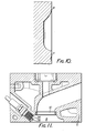
- the complex manner in which the shape of the recess progressively changes will be apparent from Figures 2 to 10.
- each half of the combustion chamber has a plan area slightly less than half that of the cylinder bore
- the cylinder head affords two plane areas 18 which are approached very closely by the piston crown at the end of the compression stroke.
- spark plug 28 shown only in Figure 11
- two spark plugs may be provided in mirror symmetrical positions.
- the inlet port is preferably of directed or helical type and in this case is of directed type.
- swirl is induced in the inlet charge of air and fuel during the inlet stroke.
- the swirl pattern is altered by the combustion chamber configuration.
- the increase in depth of the combustion chamber adjacent the initial portion of each arc 22 both along its length and radially inwards results in a separate swirl pattern being produced in each half of the combustion chamber.
- Each air pattern is in the same sense, that is to say anti-clockwise as seen in Figure 1.
- combustion chamber has been described as formed in the cylinder head it will be appreciated that the head may be substantially plane, though provided with inlet and exhaust ports, and that the combustion chamber may be provided in the crown of the piston.
Landscapes
- Engineering & Computer Science (AREA)
- Chemical & Material Sciences (AREA)
- Combustion & Propulsion (AREA)
- Mechanical Engineering (AREA)
- General Engineering & Computer Science (AREA)
- Combustion Methods Of Internal-Combustion Engines (AREA)
Applications Claiming Priority (2)
| Application Number | Priority Date | Filing Date | Title |
|---|---|---|---|
| GB08401928A GB2153428B (en) | 1984-01-25 | 1984-01-25 | Spark ignited i c engine combustion chambers |
| GB8401928 | 1984-01-25 |
Publications (3)
| Publication Number | Publication Date |
|---|---|
| EP0150989A2 true EP0150989A2 (de) | 1985-08-07 |
| EP0150989A3 EP0150989A3 (en) | 1985-08-21 |
| EP0150989B1 EP0150989B1 (de) | 1988-05-25 |
Family
ID=10555503
Family Applications (1)
| Application Number | Title | Priority Date | Filing Date |
|---|---|---|---|
| EP85300467A Expired EP0150989B1 (de) | 1984-01-25 | 1985-01-24 | Brennkraftmaschine mit Fremdzündung |
Country Status (8)
| Country | Link |
|---|---|
| US (1) | US4686949A (de) |
| EP (1) | EP0150989B1 (de) |
| JP (1) | JP2648589B2 (de) |
| KR (1) | KR960006010B1 (de) |
| AU (1) | AU569772B2 (de) |
| DE (1) | DE3562940D1 (de) |
| ES (1) | ES539805A0 (de) |
| GB (1) | GB2153428B (de) |
Families Citing this family (2)
| Publication number | Priority date | Publication date | Assignee | Title |
|---|---|---|---|---|
| JPS60228722A (ja) * | 1984-04-26 | 1985-11-14 | Mazda Motor Corp | エンジンの燃焼室 |
| US5445135A (en) * | 1994-02-03 | 1995-08-29 | Feuling; James J. | Two-valve combustion chamber system |
Citations (6)
| Publication number | Priority date | Publication date | Assignee | Title |
|---|---|---|---|---|
| FR2317491A1 (fr) * | 1975-07-09 | 1977-02-04 | Bayerische Motoren Werke Ag | Chambre de combustion pour moteurs a combustion interne a compression de melange et allumage separe |
| US4121544A (en) * | 1975-01-24 | 1978-10-24 | May Michael G | Internal combustion engine |
| WO1982002924A1 (en) * | 1981-02-27 | 1982-09-02 | Stace Richard John Lesley | Internal combustion engine'and cylinder head therefor |
| US4359981A (en) * | 1979-09-20 | 1982-11-23 | Toyota Jidosha Kogyo Kabushiki Kaisha | High compression type internal combustion engine |
| DE3138328A1 (de) * | 1981-09-25 | 1983-04-14 | August, Paul, Dipl.-Ing. Dr.h.c., Barcelona | Verbesserung der gemischbildung fuer brennkraftmaschinen |
| EP0097409A2 (de) * | 1982-06-21 | 1984-01-04 | Motortech, Inc. | Brennkraftmaschine |
Family Cites Families (10)
| Publication number | Priority date | Publication date | Assignee | Title |
|---|---|---|---|---|
| GB609832A (en) * | 1945-02-21 | 1948-10-07 | Schweizerische Lokomotiv | Improvements in or relating to combustion chambers for internal combustion engines |
| GB833684A (en) * | 1956-12-20 | 1960-04-27 | Ricardo & Co Engineers | Internal combustion engines of the liquid fuel injection compression ignition type |
| GB891738A (en) * | 1959-09-22 | 1962-03-21 | Ricardo & Co Engineers | Internal combustion engine of the liquid fuel injection compression ignition type |
| DE1526338A1 (de) * | 1966-12-10 | 1970-02-05 | Robur Werke Lastkraftwagen Und | Brennraum bei Vergasermotoren,insbesondere Viertaktmotoren |
| JPS5293812A (en) * | 1976-02-04 | 1977-08-06 | Toyota Motor Corp | Combustion chamber of internal combustion engine |
| JPS5949407B2 (ja) * | 1976-11-15 | 1984-12-03 | トヨタ自動車株式会社 | 内燃機関の燃焼室 |
| GB2019936A (en) * | 1978-03-31 | 1979-11-07 | Chrysler France | Internal combustion engine combustion chambers |
| JPS55135123U (de) * | 1979-03-20 | 1980-09-25 | ||
| JPS5914610B2 (ja) * | 1981-08-10 | 1984-04-05 | トヨタ自動車株式会社 | 内燃機関の燃焼室 |
| JPS5853630A (ja) * | 1981-09-28 | 1983-03-30 | Toyota Motor Corp | 内燃機関 |
-
1984
- 1984-01-25 GB GB08401928A patent/GB2153428B/en not_active Expired
-
1985
- 1985-01-24 ES ES539805A patent/ES539805A0/es active Granted
- 1985-01-24 EP EP85300467A patent/EP0150989B1/de not_active Expired
- 1985-01-24 JP JP60010000A patent/JP2648589B2/ja not_active Expired - Fee Related
- 1985-01-24 KR KR1019850000434A patent/KR960006010B1/ko not_active IP Right Cessation
- 1985-01-24 DE DE8585300467T patent/DE3562940D1/de not_active Expired
- 1985-01-25 US US06/695,172 patent/US4686949A/en not_active Expired - Lifetime
- 1985-01-25 AU AU38077/85A patent/AU569772B2/en not_active Ceased
Patent Citations (6)
| Publication number | Priority date | Publication date | Assignee | Title |
|---|---|---|---|---|
| US4121544A (en) * | 1975-01-24 | 1978-10-24 | May Michael G | Internal combustion engine |
| FR2317491A1 (fr) * | 1975-07-09 | 1977-02-04 | Bayerische Motoren Werke Ag | Chambre de combustion pour moteurs a combustion interne a compression de melange et allumage separe |
| US4359981A (en) * | 1979-09-20 | 1982-11-23 | Toyota Jidosha Kogyo Kabushiki Kaisha | High compression type internal combustion engine |
| WO1982002924A1 (en) * | 1981-02-27 | 1982-09-02 | Stace Richard John Lesley | Internal combustion engine'and cylinder head therefor |
| DE3138328A1 (de) * | 1981-09-25 | 1983-04-14 | August, Paul, Dipl.-Ing. Dr.h.c., Barcelona | Verbesserung der gemischbildung fuer brennkraftmaschinen |
| EP0097409A2 (de) * | 1982-06-21 | 1984-01-04 | Motortech, Inc. | Brennkraftmaschine |
Also Published As
| Publication number | Publication date |
|---|---|
| US4686949A (en) | 1987-08-18 |
| EP0150989A3 (en) | 1985-08-21 |
| ES8601392A1 (es) | 1985-11-01 |
| ES539805A0 (es) | 1985-11-01 |
| GB8401928D0 (en) | 1984-02-29 |
| EP0150989B1 (de) | 1988-05-25 |
| KR960006010B1 (ko) | 1996-05-06 |
| JP2648589B2 (ja) | 1997-09-03 |
| AU569772B2 (en) | 1988-02-18 |
| GB2153428A (en) | 1985-08-21 |
| GB2153428B (en) | 1987-10-28 |
| JPS60159330A (ja) | 1985-08-20 |
| DE3562940D1 (en) | 1988-06-30 |
| KR850005551A (ko) | 1985-08-26 |
| AU3807785A (en) | 1985-08-01 |
Similar Documents
| Publication | Publication Date | Title |
|---|---|---|
| US4207843A (en) | Compression ignition direct injection internal combustion engine | |
| EP0097409B1 (de) | Brennkraftmaschine | |
| US5351665A (en) | Internal combustion engine | |
| US5320075A (en) | Internal combustion engine with dual ignition for a lean burn | |
| US4211189A (en) | Internal combustion engine with dual induction system and more particularly to combustion chamber design thereof | |
| JP3030415B2 (ja) | 筒内噴射エンジンのピストン | |
| GB2387638A (en) | A piston for a direct injection spark ignition engine including a shallow bowl with maximum depth of one to five millimetres | |
| JP7155918B2 (ja) | エンジンの燃焼室構造 | |
| US5970945A (en) | Barrier divided combustion chamber for fuel injection two-stroke engine | |
| US4545344A (en) | Diesel engine having turbulent combustion chamber | |
| US4367707A (en) | Combustion chamber of an internal combustion engine | |
| US6129066A (en) | Engine piston having a gas turbulence generating surface | |
| JPH01305121A (ja) | 2サイクルディーゼルエンジン | |
| US6868817B2 (en) | Simplified combustion chamber | |
| US4175501A (en) | Internal combustion engine with an auxiliary combustion chamber | |
| EP0150989B1 (de) | Brennkraftmaschine mit Fremdzündung | |
| US4459804A (en) | Multiple spark ignition internal combustion engine with exhaust gas recirculation | |
| JPS5838610B2 (ja) | 内燃機関 | |
| JP7470036B2 (ja) | ディーゼルエンジン | |
| JP2022083622A (ja) | エンジンの燃焼室構造 | |
| US4125105A (en) | Four cycle internal combustion engine | |
| US5862789A (en) | Applied ignition internal combustion engine whose pistons have elliptical recesses | |
| US11624313B2 (en) | Engine with combustion chamber | |
| US11512663B2 (en) | Engine with combustion chamber | |
| GB1587842A (en) | Internal combustion piston engine |
Legal Events
| Date | Code | Title | Description |
|---|---|---|---|
| PUAI | Public reference made under article 153(3) epc to a published international application that has entered the european phase |
Free format text: ORIGINAL CODE: 0009012 |
|
| PUAL | Search report despatched |
Free format text: ORIGINAL CODE: 0009013 |
|
| AK | Designated contracting states |
Designated state(s): DE FR GB IT NL SE |
|
| AK | Designated contracting states |
Designated state(s): DE FR GB IT NL SE |
|
| 17P | Request for examination filed |
Effective date: 19850918 |
|
| 17Q | First examination report despatched |
Effective date: 19860428 |
|
| ITF | It: translation for a ep patent filed |
Owner name: BARZANO' E ZANARDO ROMA S.P.A. |
|
| GRAA | (expected) grant |
Free format text: ORIGINAL CODE: 0009210 |
|
| AK | Designated contracting states |
Kind code of ref document: B1 Designated state(s): DE FR IT NL SE |
|
| REF | Corresponds to: |
Ref document number: 3562940 Country of ref document: DE Date of ref document: 19880630 |
|
| ET | Fr: translation filed | ||
| PLBE | No opposition filed within time limit |
Free format text: ORIGINAL CODE: 0009261 |
|
| STAA | Information on the status of an ep patent application or granted ep patent |
Free format text: STATUS: NO OPPOSITION FILED WITHIN TIME LIMIT |
|
| 26N | No opposition filed | ||
| ITTA | It: last paid annual fee | ||
| EAL | Se: european patent in force in sweden |
Ref document number: 85300467.9 |
|
| PGFP | Annual fee paid to national office [announced via postgrant information from national office to epo] |
Ref country code: SE Payment date: 20010105 Year of fee payment: 17 |
|
| PGFP | Annual fee paid to national office [announced via postgrant information from national office to epo] |
Ref country code: FR Payment date: 20010125 Year of fee payment: 17 |
|
| PGFP | Annual fee paid to national office [announced via postgrant information from national office to epo] |
Ref country code: NL Payment date: 20010131 Year of fee payment: 17 |
|
| PG25 | Lapsed in a contracting state [announced via postgrant information from national office to epo] |
Ref country code: SE Free format text: LAPSE BECAUSE OF NON-PAYMENT OF DUE FEES Effective date: 20020125 |
|
| PGFP | Annual fee paid to national office [announced via postgrant information from national office to epo] |
Ref country code: DE Payment date: 20020227 Year of fee payment: 18 |
|
| PG25 | Lapsed in a contracting state [announced via postgrant information from national office to epo] |
Ref country code: NL Free format text: LAPSE BECAUSE OF NON-PAYMENT OF DUE FEES Effective date: 20020801 |
|
| EUG | Se: european patent has lapsed |
Ref document number: 85300467.9 |
|
| PG25 | Lapsed in a contracting state [announced via postgrant information from national office to epo] |
Ref country code: FR Free format text: LAPSE BECAUSE OF NON-PAYMENT OF DUE FEES Effective date: 20020930 |
|
| NLV4 | Nl: lapsed or anulled due to non-payment of the annual fee |
Effective date: 20020801 |
|
| REG | Reference to a national code |
Ref country code: FR Ref legal event code: ST |
|
| PG25 | Lapsed in a contracting state [announced via postgrant information from national office to epo] |
Ref country code: DE Free format text: LAPSE BECAUSE OF NON-PAYMENT OF DUE FEES Effective date: 20030801 |