EP0150858A2 - Vierradlenksystem für ein Fahrzeug - Google Patents
Vierradlenksystem für ein Fahrzeug Download PDFInfo
- Publication number
- EP0150858A2 EP0150858A2 EP85101023A EP85101023A EP0150858A2 EP 0150858 A2 EP0150858 A2 EP 0150858A2 EP 85101023 A EP85101023 A EP 85101023A EP 85101023 A EP85101023 A EP 85101023A EP 0150858 A2 EP0150858 A2 EP 0150858A2
- Authority
- EP
- European Patent Office
- Prior art keywords
- steering
- wheels
- vehicle speed
- angle
- vehicle
- Prior art date
- Legal status (The legal status is an assumption and is not a legal conclusion. Google has not performed a legal analysis and makes no representation as to the accuracy of the status listed.)
- Granted
Links
Images


Classifications
-
- B—PERFORMING OPERATIONS; TRANSPORTING
- B62—LAND VEHICLES FOR TRAVELLING OTHERWISE THAN ON RAILS
- B62D—MOTOR VEHICLES; TRAILERS
- B62D7/00—Steering linkage; Stub axles or their mountings
- B62D7/06—Steering linkage; Stub axles or their mountings for individually-pivoted wheels, e.g. on king-pins
- B62D7/14—Steering linkage; Stub axles or their mountings for individually-pivoted wheels, e.g. on king-pins the pivotal axes being situated in more than one plane transverse to the longitudinal centre line of the vehicle, e.g. all-wheel steering
- B62D7/15—Steering linkage; Stub axles or their mountings for individually-pivoted wheels, e.g. on king-pins the pivotal axes being situated in more than one plane transverse to the longitudinal centre line of the vehicle, e.g. all-wheel steering characterised by means varying the ratio between the steering angles of the steered wheels
- B62D7/1554—Steering linkage; Stub axles or their mountings for individually-pivoted wheels, e.g. on king-pins the pivotal axes being situated in more than one plane transverse to the longitudinal centre line of the vehicle, e.g. all-wheel steering characterised by means varying the ratio between the steering angles of the steered wheels comprising a fluid interconnecting system between the steering control means of the different axles
- B62D7/1572—Steering linkage; Stub axles or their mountings for individually-pivoted wheels, e.g. on king-pins the pivotal axes being situated in more than one plane transverse to the longitudinal centre line of the vehicle, e.g. all-wheel steering characterised by means varying the ratio between the steering angles of the steered wheels comprising a fluid interconnecting system between the steering control means of the different axles provided with electro-hydraulic control means
-
- B—PERFORMING OPERATIONS; TRANSPORTING
- B62—LAND VEHICLES FOR TRAVELLING OTHERWISE THAN ON RAILS
- B62D—MOTOR VEHICLES; TRAILERS
- B62D7/00—Steering linkage; Stub axles or their mountings
- B62D7/06—Steering linkage; Stub axles or their mountings for individually-pivoted wheels, e.g. on king-pins
- B62D7/14—Steering linkage; Stub axles or their mountings for individually-pivoted wheels, e.g. on king-pins the pivotal axes being situated in more than one plane transverse to the longitudinal centre line of the vehicle, e.g. all-wheel steering
- B62D7/15—Steering linkage; Stub axles or their mountings for individually-pivoted wheels, e.g. on king-pins the pivotal axes being situated in more than one plane transverse to the longitudinal centre line of the vehicle, e.g. all-wheel steering characterised by means varying the ratio between the steering angles of the steered wheels
- B62D7/1518—Steering linkage; Stub axles or their mountings for individually-pivoted wheels, e.g. on king-pins the pivotal axes being situated in more than one plane transverse to the longitudinal centre line of the vehicle, e.g. all-wheel steering characterised by means varying the ratio between the steering angles of the steered wheels comprising a mechanical interconnecting system between the steering control means of the different axles
- B62D7/1536—Steering linkage; Stub axles or their mountings for individually-pivoted wheels, e.g. on king-pins the pivotal axes being situated in more than one plane transverse to the longitudinal centre line of the vehicle, e.g. all-wheel steering characterised by means varying the ratio between the steering angles of the steered wheels comprising a mechanical interconnecting system between the steering control means of the different axles provided with hydraulic assistance
-
- B—PERFORMING OPERATIONS; TRANSPORTING
- B62—LAND VEHICLES FOR TRAVELLING OTHERWISE THAN ON RAILS
- B62D—MOTOR VEHICLES; TRAILERS
- B62D7/00—Steering linkage; Stub axles or their mountings
- B62D7/06—Steering linkage; Stub axles or their mountings for individually-pivoted wheels, e.g. on king-pins
- B62D7/14—Steering linkage; Stub axles or their mountings for individually-pivoted wheels, e.g. on king-pins the pivotal axes being situated in more than one plane transverse to the longitudinal centre line of the vehicle, e.g. all-wheel steering
- B62D7/15—Steering linkage; Stub axles or their mountings for individually-pivoted wheels, e.g. on king-pins the pivotal axes being situated in more than one plane transverse to the longitudinal centre line of the vehicle, e.g. all-wheel steering characterised by means varying the ratio between the steering angles of the steered wheels
- B62D7/1554—Steering linkage; Stub axles or their mountings for individually-pivoted wheels, e.g. on king-pins the pivotal axes being situated in more than one plane transverse to the longitudinal centre line of the vehicle, e.g. all-wheel steering characterised by means varying the ratio between the steering angles of the steered wheels comprising a fluid interconnecting system between the steering control means of the different axles
- B62D7/1563—Steering linkage; Stub axles or their mountings for individually-pivoted wheels, e.g. on king-pins the pivotal axes being situated in more than one plane transverse to the longitudinal centre line of the vehicle, e.g. all-wheel steering characterised by means varying the ratio between the steering angles of the steered wheels comprising a fluid interconnecting system between the steering control means of the different axles provided with fluid control means
-
- B—PERFORMING OPERATIONS; TRANSPORTING
- B62—LAND VEHICLES FOR TRAVELLING OTHERWISE THAN ON RAILS
- B62D—MOTOR VEHICLES; TRAILERS
- B62D7/00—Steering linkage; Stub axles or their mountings
- B62D7/06—Steering linkage; Stub axles or their mountings for individually-pivoted wheels, e.g. on king-pins
- B62D7/14—Steering linkage; Stub axles or their mountings for individually-pivoted wheels, e.g. on king-pins the pivotal axes being situated in more than one plane transverse to the longitudinal centre line of the vehicle, e.g. all-wheel steering
- B62D7/15—Steering linkage; Stub axles or their mountings for individually-pivoted wheels, e.g. on king-pins the pivotal axes being situated in more than one plane transverse to the longitudinal centre line of the vehicle, e.g. all-wheel steering characterised by means varying the ratio between the steering angles of the steered wheels
- B62D7/159—Steering linkage; Stub axles or their mountings for individually-pivoted wheels, e.g. on king-pins the pivotal axes being situated in more than one plane transverse to the longitudinal centre line of the vehicle, e.g. all-wheel steering characterised by means varying the ratio between the steering angles of the steered wheels characterised by computing methods or stabilisation processes or systems, e.g. responding to yaw rate, lateral wind, load, road condition
Definitions
- the present invention relates to a control system for steering both of a front wheel pair and a rear wheel pair of a vehicle such as a motor vehicle in accordance with a driver's steering input.
- the control system comnprises steering input means, front steering means and rear steering means.
- the input means is adapted to be operated manually for determining a steering input indicative of a driver's steering command.
- the front steering means is connected with the input means for determining a first output angle from the steering input in accordance with a first transfer characteristic between the steering input and the first output angle, and controlling a steering angle of the front wheels so that the steering angle of the front wheels is maintained equal to the first output angle.
- the rear steering means is connected with the input means for determining a second output angle from the steering input in accordance with a second transfer characteristic between the steering input and the second output angle, which is different from the first transfer characteristic, and controlling a steering angle of the rear wheels so that the steering angle of the rear wheels is maintained equal to the second output angle.
- Fig. 1 shows a four-wheel steering system of a conventional type as disclosed in Japanese Patent provisionally published application, provisional publication No. 58-20565.
- a steering input (which is a driver's steering command and which is usually a steering angle or angular displacement 0 of a steering wheel) is transmitted through a steering gear 1 to front road wheels 3 of a vehicle 2, and simultaneously to rear road wheels 5 through a rear wheel steering mechanism 4.
- a steering angle of the front wheels 3 is maintained equal to a steering gear ratio 1/N of the steering gear 1 times the steering input e, while at the same time a steering angle of the rear wheels 5 is maintained equal to a gear ratio Kr of the rear steering mechanism 4 times the gear ratio 1/N of the steering gear 1 times the steering input e.
- a transfer characteristic between the steering input and the front wheel steering angle and a transfer characteristic between the steering input and the rear wheel steering angle are fixed and substantially identical to each other from the viewpoint of an analysis of a turning movement of a wheeled vehicle. Therefore, this system cannot steer the front wheels and rear wheels individually in accordance with respective transfer characteristics and cannot provide a satisfactory cornering characteristic and steering stability of a vehicle.
- the present invention is based on the following consideration.
- a turning movement of a wheeled vehicle is basically planar, and generally described by a yaw rate or yaw angular velocity ($ or ⁇ ) and a lateral acceleration (a) of the vehicle.
- the yaw rate is the time rate of change of angular displacement of the vehicle about a vertical axis through the center of gravity 2a of the vehicle 2.
- the lateral acceleration is an acceleration of the center of gravity 2a along a lateral axis of the vehicle.
- a movement of a vehicle having steerable front and steerable rear wheels is determined by the sum of a turning behavior due to a yaw rate ⁇ 1 and a lateral acceleration ai which are both caused by a steering angle ⁇ 1 of the front wheels, and a turning behavior due to a yaw rate ⁇ 2 and a lateral acceleration ⁇ 2 which are both caused by a steering angle ⁇ 2 of the rear wheels. Therefore, a total yaw rate ⁇ and a total lateral acceleration a of the vehicle are expressed as follows:
- each of the transfer functions H 1 (s), H 2 (s), G 1 (s) and G 2 (s) is known per se.
- Masato Abe “Sharyo no Undo to Seigyo (Movement and Control of Vehicle)" Kyoritsu Shuppan Kabushiki Kaisha, discloses these transfer functions.
- the description of this publication necessary to determine these transfer functions is hereby incorporated by reference.
- the transfer functions H 1 (s), H 2 (s), G 1 (s) and G 2 (s) can be determined easily, so that the transfer functions Xi(s) and X 2 (s) to obtain the desired values ⁇ 0 , ao can be determined from the equations (17) and (18).
- each of the transfer functions is a function of a steering frequency
- the sign s of each transfer function can be replaced by Jw, provided that J is an imaginary number, and w is the steering frequency. Therefore, the transfer functions Xi(s) and X 2 (s) obtained from the equations (17) and (18) provide frequency response characteristics of both gain and phase difference as shown in Figs. 18A and 18B.
- each of the transfer functions Hi(s), H 2 (s), Gi(s) and G 2 (s) is a function of the vehicle speed. Accordingly, each characteristic of Figs. 18A and 18B changes from a broken line curve to a solid line curve with increase of the vehicle speed as shown by an arrow. As shown in Fig. 18A, both of the gain and the phase lead of Xi(s) decrease when the vehicle speed increases. The gain of Xz(s) changes from a negative side to a positive side with increase of the vehicle speed, as shown in Fig. 18B. The phase difference of X z (s) changes from a phase lead side to a phase lag side with increase of the vehicle speed as shown in Fig. 18B.
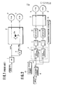
- a first embodiment of the present invention is shown in Fig. 2.
- a control system of the first embodiment for steering a vehicle 2 through front wheels 3 and rear wheels 5 has a steering sensor 6 which senses a steering input produced by a driver.
- the steering input is an angular displacement e of a steering wheel of the vehicle 2, for example.
- the steering sensor 6 is connected to a control unit 7 which has a front wheel steering angle control circuit 8 and a rear wheel steering angle control circuit 9. Both circuits of the control unit 7 receives a signal of a vehicle speed sensor 10 as well as a signal of the steering input sensor 6.
- the vehicle speed sensor 10 senses a speed V of the vehicle 2.
- the control unit 7 determines the above-mentioned transfer functions Hi(s), Hz(s), Gi(s) and G 2 (s) from the vehicle speed V sensed by the vehicle speed sensor 10 and a steering frequency based on the steering input ⁇ .
- the front wheel steering angle control circuit 8 determines the transfer function Xi(s) corresponding to the desired values ⁇ 0 and ao from the above-mentioned equation (17). Then, the front wheel circuit 8 determines the steering angle ⁇ 1 of the front wheels 3 from the above-mentioned equation (9) by use of Xi(s) and the steering input ⁇ .
- the rear wheel steering angle control circuit 9 determines the transfer function Xz(s) corresponding to the desired values ⁇ 0 and ao from the equation (18), and then determines the steering angle ⁇ 2 of the rear wheels 5 from the equation (10).
- An output signal of the circuit 8, indicative of the front wheel steering angle 6 1 is sent to a front wheel actuator 13 through an amplifier 11 for amplifying the signal.
- An output signal of the circuit 9, indicative of the rear wheel steering angle 6 2 is sent to a rear wheel actuator 14 through an amplifier 12.
- the actuator 13 steers the front wheels 3 through the determined steering angle ⁇ 1 in accordance with the output signal of the circuit 8.
- the actuator 14 steers the rear wheels 5 through the determined steering angle 6 2 in accordance with the output signal of the circuit 9.
- the vehicle 2 is steered through both the front and rear wheels so that the desired values ⁇ 0 and ao expressed by the equations (13) and (14) can be obtained. Consequently, the steering control system of the first embodiment can improve the vehicle stability and control (or directional control characteristics) remarkably, and make an ideal four-wheel steering possible.
- This control system employs the transfer functions X 1 (s) and X 2 (s) as shown in Figs. 18A and 18B. Therefore, the response characteristic of the front wheel steering angle is determined by X (s), as shown in Fig. 3A.
- X (s) the response characteristic of the front wheel steering angle is determined by X (s), as shown in Fig. 3A.
- Each characteristic curve of Fig. 3A changes from a broken line to a solid line when the vehicle speed becomes high.
- the front wheels 3 are turned in such a positive direction as to increase a direction change of the vehicle. An amount of a turn of the front wheels in the positive direction is decreased as the steering frequency decreases, or as the vehicle speed increases.
- the response of the front wheels 3 leads the steering input, and the phase lead of the front wheels 3 with respect to the steering input is decreased as the steering frequency decreases or as the vehicle speed increases.
- the response characteristic of the rear wheel steering angle is determined by X 2 (s), as shown in Fig. 3B.
- Each characteristic curve of Fig. 3B changes from a broken line to a solid line when the vehicle speed becomes high.
- the rear wheels 5 are turned in the positive direction to increase the direction change of the vehicle. (That is, the rear wheels 5 are turned in a direction opposite to a turn direction of the front wheels 3 with respect to a longitudinal line of the vehicle).
- the rear wheels 5 are turned in such a negative direction as to decrease a direction change of the vehicle. (That is, the rear wheels 5 are turned in the same direction as the front wheels 3 are turned).
- the response of the rear wheels 5 leads the steering input when the vehicle speed is low, and lags the steering input when the vehicle speed is high.
- G 1 and G 2 are, respectively, values (stationary gains) of the gains of the front wheels 3 and rear wheels 5 when the steering frequency is approximately zero.
- the values G 1 and G 2 vary with the vehicle speed as shown in Figs. 4A and 4B.
- a solid line in Fig. 4A the amount of a turn of the front wheels 3 in the positive direction decreases when the vehicle speed becomes high.
- the amount of a turn of the rear wheels 5 in the positive or negative direction is varied as shown by a solid line in Fig. 4B.
- a broken line of Fig. 4A shows a characteristic obtained when the control of the amount of a turn of the front wheels in the positive direction based on the vehicle speed is not performed.
- a broken line of Fig. 4B shows a characteristic obtained when the rear wheels are controlled only in the negative direction without a control in the positive direction. The direction control characteristic of the vehicle can be improved even when the characteristics of the broken lines of Figs. 4A and 4B are employed.
- a transfer function adjuster 15 for modifying the transfer functions X i (s) and X z (s), into the control system of this embodiment, as shown in Fig. 2.
- a yaw rate gain of the vehicle is determined by the transfer functions X 1 (s) and X 2 (s). Therefore, the adjuster 15 is arranged to adapt the yaw rate gain of the vehicle to vehicle speed, side wind, weather condition, road condition, acceleration or deceleration of the vehicle, vehicle weight, weight distribution between the front and rear axles, and/or driver's taste, by modifying X 1 (s) and/or X 2 (s).
- the transfer function adjuster 15 is arranged to decrease the yaw rate gain (a ratio of the yaw rate to the steering input) with increase of the vehicle speed in order to improve the vehicle stability at high vehicle speeds. Therefore, the adjuster 15 decreases the transfer function X 1 (s) (the amount of a turn of the front wheels in the positive direction) determined by the control circuit 8, and increases the transfer function X 2 (s) (the amount of a turn of the rear wheels in the negative direction) determined by the circuit 9, as the vehicle speed increases.
- the transfer function adjuster 15 may be arranged to decrease the yaw rate gain by decreasing X i (s) and increasing X 2 (s) when any one or more of conditions of side wind, weather and road surface become worse for the vehicle control and stability. For example, the yaw rate gain is decreased when the side wind becomes stronger, when the weather becomes rainy, or when the road becomes rugged.
- the adjuster 15 may be arranged to decrease X i (s) and increase X 2 (s) as the vehicle acceleration or deceleration increases.
- the adjuster 15 may be arranged to decrease the yaw rate gain with increase of the vehicle weight.
- the adjuster 15 may be arranged to decrease the yaw rate gain as the weight on the rear axle increases.
- the adjuster 15 may be arranged to adjust the phase differences in either case.
- the adjuster 15 modifies X 1 (s) and X 2 (s) so as to adjust the yaw rate gain to a value indicated by a driver's manual operation.
- Fig. 5 shows the control system of Fig. 2 more concretely.
- Right and left steering linkages 16 supports the right and left front wheels 3, respectively, on a vehicle body so that the front wheels 3 are steerable.
- Right and left steering linkages 17 support the rear wheels 5, respectively, on the vehicle body so that the rear wheels 5 are also steerable.
- the front wheel actuator 13 shown in Fig. 2 is interposed between the front steering linkages 16.
- the rear wheel actuator 14 is interposed between the rear steering linkage 17.
- Each of the actuators 13 and 14 is a double-acting hydraulic actuator.
- the actuators 13 and 14 are controlled by servo valves 18 and 19, respectively.
- a hydraulic fluid pressure is supplied to the servo valves 18 and 19 by a common hydraulic circuit.
- An oil pump 22 is driven by an engine 20 which is mounted on the vehicle together with a transmission 21.
- the oil pump 22 sucks oil from an oil reservoir 23, and discharges the oil to an unload valve 24, which controls the pressure of the oil at a predetermined value and supplies the pressurized oil to an accumulator 25.
- the oil is supplied from the accumulator 25 to the servo valves 18 and 19 through a supply conduit 26.
- a return conduit 27 conveys an unnecessary oil from the servo valves 18 and 19 and the unload valve 24.
- the steering sensor 6 senses the angular displacement ⁇ of the steering wheel 30, and the vehicle speed sensor 10 senses an output rpm of the transmission 21 (vehicle speed V).
- the front and rear wheel steering angle control circuits 8 and 9 of the control unit 7 receives the steering input 0 sensed by the steering sensor 6, and the vehicle speed V sensed by the vehicle speed sensor 10, and produces the output electric signals indicative of the front and rear wheel steering angles 6 1 and 6 2 , respectively.
- the output signals of the circuits 8 and 9 are sent, respectively, through the amplifiers 11 and 12 to the servo valves 18 and 19.
- the front servo valve 18 supplies the oil of the supply conduit 26 to one of two working chambers of the front wheel actuator 13 and makes the other chamber open to the return conduit 27, so that the piston of the actuator 13 moves in a direction determined by the signal of the control circuit 8, and steers the front wheels 3 in the determined direction.
- the servo valve 19 steers the rear wheels 5 by supplying the oil from the supply conduit 26 to one of two working chambers of the rear wheel actuator 14 in accordance with the signal of the control circuit 9.
- Front and rear wheel steering angle sensors 28 and 29 sense amounts of angular movements of the front and rear wheels 3 and 5, respectively.
- An output signal of the front wheel steering angle sensor 28 is compared with the signal of the control circuit 8, and the servo valve 18 stops its control when the sensed amount of the angular displacement of the front wheels 3 is equal to the front wheel steering angle g 1 determined by the circuit 8. Similarly, the rear servo valve 19 stops its control when the amount of the angular displacement of the rear wheels 5 is equal to the rear wheel steering angle ⁇ 2 determined by the circuit 9.
- the servo valves 18 and 19 can maintain the angular positions of the front and rear wheels 3 and 5 at the desired steering angles ⁇ 1 and 6 2 , respectively, by shutting off the actuator 13 and 14 from both of the supply and return conduits 26 and 27.
- a second embodiment of the present invention is shown in Fig. 6.
- the rear wheel steering system of this embodiment is the same as that of the first embodiment.
- the front wheel steering system of this embodiment is different from that of the first embodiment in that the front wheels 3 are steered first through a mechanical steering gear 1, and secondly through an electrical control circuit 8 similar to the control circuit 8 of the first embodiment.
- the desired front wheel steering angle 6 1 is attained by a cooperation of the steering mechanism and the control circuit.
- the control circuit 8 steers the front wheels 3 through the amplifier 11 and the front wheel actuator 13 in accordance with the determined corrective steering angle 6 1 ' in such a manner as to give assistance to the front wheel steering mechanism.
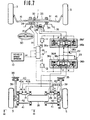
- Fig. 7 shows the control system of Fig. 6 concretely.
- the steering gear 1 of the front wheel steering mechanism has a rack 31 interposed between right and left steering linkages 16 of the right and left front wheels 3, and a pinion 32 which is rotated by a steering wheel 30 and in engagement with the rack 31.
- a steering gear housing 33 encloses the rack 31 and pinion 32.
- the steering input 0 applied to the steering wheel 30 by the driver causes the pinion 32 to rotate, and the rack 31 to move longitudinally (toward the right or left front wheel 3), so that the front wheels 3 are steered.
- the gear housing 33 is supported on a vehicle body 35 through rubber bushes 34, and made longitudinally movable together with the rack 31, relative to the vehicle body, toward the right or left front wheel 3, by the front wheel actuator 13 of a hydraulic type.
- the front wheel actuator 13 has a piston 13a which separates two working chambers having ports A and B, respectively.
- the actuator 13 further has a piston rod 13b connected with the gear housing 33.
- the cylinder of the actuator 13 is connected with the vehicle body 35 through a rod 13c.
- the actuator 13 is controlled by a front electromagnetic spool valve 36F having solenoids 36a and 36b, and a spool 36c.
- the spool 36c is held at a neutral position shown in Fig. 7 by springs when both of the solenoids 36a and 36b are deenergized.
- the valve 36F is connected with an oil pump 22 and a reservoir 23.
- the valve 36F has a port A' connected with the port A of the front wheel actuator 13, and a port B' connected with the port B of the actuator 13.
- the solenoid 36a or 36b is energized selectively by the electric signal indicative of the corrective steering angle 6 1 ' of the front wheels, which is sent through the amplifier 11 from the front wheel steering angle control circuit 8 responsive to the steering input 0 sensed by the steering sensor 6 and the vehicle speed V sensed by the vehicle speed sensor 10.
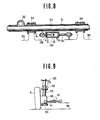
- the solenoid 36a is energized and the spool 36c of the valve 36F is moved left in Fig. 7, the fluid pressure is supplied through the port B', and accordingly the piston 13a of the actuator 13 is moved left as shown by an arrow C in Fig. 8. Therefore, the gear housing 33 causes the rubber bushes 34 to deflect, and moves left in Fig. 7, so that the front wheels 3 are steered right.
- the solenoid 36b of the valve 36F When the solenoid 36b of the valve 36F is energized and the spool 36c is moved right in Fig. 7, the fluid pressure is supplied through the port A' so that the front wheels 3 are steered left.
- the control circuit 8 controls the direction and amount of the corrective steering action of the actuator 13.
- a front wheel steering angle sensor 28 senses the corrective control action of the actuator 13.
- the valve 36F is so arranged that the actual amount sensed by the sensor 28 is maintained equal to the desired corrective steering angle 6 1 '.
- the rear wheel steering system of Fig. 7 has right and left wheel support member 38 which, respectively, support the rear wheels 5 rotatably.
- Each of the wheel support members 38 is supported on the vehicle body 35 by a radius rod 39 in the fore and aft direction of the vehicle, and by a pair of parallel lateral rods 40 and 41 in the lateral direction of the vehicle.
- a strut assembly 42 having a suspension spring 43 extends upwardly from each wheel support member 38 to the vehicle body 35.
- the lateral rod 40 of each rear wheel is provided with the actuator 14 of a hydraulic cylinder type so that a toe angle of the rear wheel 5 can be varied.
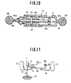
- Fig. 10 shows the actuator 14 for the left rear wheel 5.
- the actuator 14 has a piston 14a separating two working chambers having, respectively, ports A and B, and a piston rod 14b.
- the lateral rod 40 is divided into an outer portion 40a and an inner portion 40b.
- the piston rod 14b is placed between the outer and inner lateral rod portions 40a and 40b so that they are collinear.
- a circular disc 44 is interposed between the outer lateral rod portion 40a and the piston rod 14b coaxially.
- the piston rod 14b, the disc 44 and the outer lateral rod portion 40a are fixed together so as to form a single integral unit.
- the cylinder of the actuator 14 is fixed with the inner lateral rod portion 40b.
- Annular rubber bushes 45 and 46 are disposed on both sides of the disc 44.
- a tubular case 47 is fixed with the cylinder of the actuator 14. The tubular case 47 encloses the rubber bushes 45 and 46 so that they are axially immovable.
- An outboard end of the outer lateral rod portion 40a is connected with the wheel support member 38 through a rubber bush 49 and a pin 48 fixed to the support member 38 as an outboard end of the lateral rod 41.
- An inboard end of the inner lateral rod portion 40b is connected with the vehicle body 35 through a rubber bush 51 and a pin 50 fixed to the vehicle body 35 as an inboard end of the lateral rod 41.
- the left and right actuators 14 for the left and right rear wheels 5 are controlled by a rear electromagnetic spool valve 36R similar to the front valve 36F.
- a port A' of the rear valve 36R is connected to the outboard port B of the left actuator 14 for the left rear wheel 5 and the inboard port A of the right actuator 14 for the right rear wheel 5.
- a port B' of the rear valve 36R is connected to the inboard port A of the left actuator 14 for the left rear wheel 5, and the outboard port B of the right actuator 14 for the right rear wheel 5.
- the electric signal indicative of the rear wheel steering angle 6 2 , produced by the control circuit 9 is sent through the amplifier 12 to the valve 36R.
- a solenoid 36a or a solenoid 36b of the valve 36R is selectively energized by the signal of the circuit 9.
- the solenoid 36b When the solenoid 36b is energized and the spool 36c is moved right in Fig. 7, the valve 36R supplies the fluid pressure through the port A' to the outboard port B of the left rear wheel actuator 14 and the inboard port A of the right rear actuator 14. Therefore, the piston rod 14b of the left rear wheel actuator 14 moves right in Fig. 10 and compresses the rubber bush 46, so that the left rear wheel actuator 14 shortens.
- the left rear wheel 5 is steered to a position shown by a two-dot chain line in Fig. 7.
- the right rear actuator 14 is lengthened, so the right rear wheel 5 is steered in the same direction as the left rear wheel 5.
- the solenoid 36a of the valve 36R is energized, the valve 36R moves its spool 36c left in Fig. 7 and supplies the fluid pressure through the port B' to the inboard port A of the left rear wheel actuator 14 and the outboard port B of the right rear wheel actuator 14. Therefore, the right rear wheel 5 is steered to a position shown by a two-dot chain line in Fig.
- a rear wheel steering angle sensor 29 senses the steering angle of the rear wheels 5 by sensing a stroke of one of the actuators 14.
- the control circuit 9 controls steering direction and amount of the rear wheels, and the valve 36R maintains the steering angle sensed by the sensor 29 equal to the desired steering angle 6 2 .
- a front wheel steering system shown in Fig. 11 in place of the front wheel steering system shown in Fig. 7.
- right and left steering linkages 16 of the right and left front wheels are connected with each other by a tie rod 52.
- the tie rod 52 is liked to the vehicle body 35 through a link 53.
- the steering gear 1 of Fig. 11 is a recirculating ball type.
- a pitman arm 1a of the steering gear 1 is connected to the tie rod 52 through the front wheel actuator 13.
- This actuator 13 is a hydraulic servo actuator. In accordance with the signal of the control circuit 8, the actuator 13 is expanded and contracted. Thus, the actuator 13 can steer the front wheels 3 in addition to a steering action of the steering gear 1. When there is no steering action of the actuator 13, the front wheels 3 are steered only by a turning movement transmitted through the steering gear 1, actuator 13, tie rod 52 and linkages 16.
- a third embodiment of the present invention is shown in Fig. 12.
- the front wheel steering system of this embodiment is the same as that of Fig. 6.
- the rear wheel steering system of the third embodiment is arranged to steer the rear wheels 5 by supplying the fluid pressure outputted by the electromagnetic valve 36 of the front wheel steering system, to the rear wheel actuator 14 through a delay means 54 such as an orifice.
- a delay means 54 such as an orifice.
- the front wheel steering mechanism, the front wheel actuator 13, and the right and left rear wheel actuators 14 of the third embodiment are arranged in the same manners those shown in Figs. 7 to 10.
- the port A of the front wheel actuator 13 is connected by a conduit 55 with the outboard port B of the left rear wheel actuator 14, and the inboard port A of the right rear wheel actuator 14.
- the port B of the front wheel actuator 13 is connected by a conduit 56 with the inboard port A of the left rear wheel actuator 14, and the outboard port B of the right rear wheel actuator 14.
- the delay means 54 has an orifice disposed in the conduit 55 for restricting the flow through the conduit 55 and an orifice disposed in the conduit 56 for restricting the flow 'through the conduit 56.
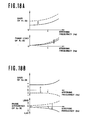
- the front wheels are steered in accordance with the characteristics shown in Fig. 14A, which are similar to the characteristics of Fig. 3A for the preceding embodiments.
- the response characteristics of the rear wheels of the third embodiment shown in Fig. 14B are different from those of the preceding embodiments.
- the steering direction of the rear wheels is always negative.
- the rear wheels are steered in the negative direction even when the vehicle speed is low.
- the amount of a turn of the rear wheels in the negative direction is increased as the vehicle speed increases as shown by an arrow in Fig. 14B.
- this amount is not increaed even in a high steering frequency range because there is provided the delay means 54.
- the phase of the rear wheel response is equal to the phase lead of the front wheels minus a phase lag due to the delay means 54.
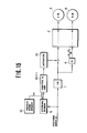
- a fourth embodiment of the present invention is shown in Fig. 15.
- the front wheel steering system of the fourth embodiment is the same as those of the second and third embodiments.
- the rear wheel steering system consists of a rear wheel steering mechanism 4 similar to that of Fig. 1.
- the system of the fourth embodiment is shown concretely in Fig. 16.
- the front wheel steering system of this embodiment has the rack and pinion type steering gear 1 and the front wheel actuator 13 for moving the steering gear housing 33.
- the front wheels are controlled by the actuator 13, control circuit 8, amplifier 11, electromagnetic spool valve 36 in the same manner as explained with reference to Figs. 6 to 8.
- the rear wheel steering mechanism 4 has right and left steering linkages 57 supporting the right and left rear wheels 5, respectively, so that the rear wheels are steerable.
- the rear wheel steering mechanism 4 further has a rack 58 interposed between the right and left linkages 57 for connecting both, and a pinion 59 engaging with the rack 58.
- the pinion 59 is fixed to one end of the shaft 61.
- the other end of the shaft 61 has a pinion 60 fixed thereto.
- the pinion 60 is engaged with the rack 31 of the front wheel steering gear 1. Therefore, a turning motion of the steering wheel 30 is transmitted through the rack 31, pinion 60, shaft 61, pinion 59, rack 58, and steering linkages 57 to the rear wheels.
- the rear wheel steering mechanism 4 is so arranged that the rear wheels 5 are steered in the same direction with respect to the longitudinal line of the vehicle as the front wheels 3.
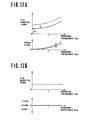
- the response characteristics of the fourth embodiment are shown in Figs. 17A and 17B.
- the response characteristics of the front wheels are similar to those of the preceding embodiments, as shown in Fig. 17A.
- the rear wheel response characteristics is shown in Fig. 17B.
- the rear wheels 5 are steered only in the negative direction which is the same direction as the steered direction of the front wheels 3.
- the amount of a turn of the rear wheels 5 in the negative direction is affected by neither the vehicle speed nor the steering frequency, but it is determined only by the steering input.
- the phase difference of the rear wheels is always zero because of the construction of the rear wheel steering mechanism 4.
- the transfer characteristic (the transfer function X i (s)) between the steering input and the front wheel steering angle, and the transfer characteristic (the transfer function X 2 (s)) between the steering input and the rear wheel steering angle are differentiated from each other so as to improve the directional control and stability of the vehicle. Therefore, the present invention makes it possible to obtain an ideal flat characteristic of the gain of vehicle (which is a ratio of the raw rate or lateral acceleration of the vehicle to the steering input), and to make the phase lag of the vehicle (which is a time delay between the steering input and the yaw rate or lateral acceleration of the vehicle) substantially zero.
Landscapes
- Engineering & Computer Science (AREA)
- Chemical & Material Sciences (AREA)
- Combustion & Propulsion (AREA)
- Transportation (AREA)
- Mechanical Engineering (AREA)
- Physics & Mathematics (AREA)
- Mathematical Physics (AREA)
- Theoretical Computer Science (AREA)
- Steering-Linkage Mechanisms And Four-Wheel Steering (AREA)
- Steering Control In Accordance With Driving Conditions (AREA)
Applications Claiming Priority (2)
| Application Number | Priority Date | Filing Date | Title |
|---|---|---|---|
| JP59015342A JPS60161265A (ja) | 1984-01-31 | 1984-01-31 | 車両の操舵方法 |
| JP15342/84 | 1984-01-31 |
Publications (3)
| Publication Number | Publication Date |
|---|---|
| EP0150858A2 true EP0150858A2 (de) | 1985-08-07 |
| EP0150858A3 EP0150858A3 (en) | 1986-02-05 |
| EP0150858B1 EP0150858B1 (de) | 1988-11-17 |
Family
ID=11886114
Family Applications (1)
| Application Number | Title | Priority Date | Filing Date |
|---|---|---|---|
| EP85101023A Expired EP0150858B1 (de) | 1984-01-31 | 1985-01-31 | Vierradlenksystem für ein Fahrzeug |
Country Status (4)
| Country | Link |
|---|---|
| US (1) | US4705131A (de) |
| EP (1) | EP0150858B1 (de) |
| JP (1) | JPS60161265A (de) |
| DE (1) | DE3566239D1 (de) |
Cited By (8)
| Publication number | Priority date | Publication date | Assignee | Title |
|---|---|---|---|---|
| EP0165706A2 (de) * | 1984-05-21 | 1985-12-27 | Kabushiki Kaisha Toyota Chuo Kenkyusho | Steuervorrichtung für den Lenkwinkel der Hinterräder eines Fahrzeuges |
| EP0199347A1 (de) * | 1985-04-25 | 1986-10-29 | Kabushiki Kaisha Toyota Chuo Kenkyusho | Steuereinheit für den Lenkwinkel der Hinterräder eines Fahrzeugs |
| EP0249967A2 (de) * | 1986-06-20 | 1987-12-23 | Toyota Jidosha Kabushiki Kaisha | Vorrichtung zur Kontrolle des Lenkwinkels eines Hinterrades |
| EP0254248A1 (de) * | 1986-07-19 | 1988-01-27 | Bayerische Motoren Werke Aktiengesellschaft, Patentabteilung AJ-3 | Hinterradsteuerung von Kraftfahrzeugen |
| FR2604680A1 (fr) * | 1986-10-01 | 1988-04-08 | Daimler Benz Ag | Vehicule automobile avec direction de roues avant et direction de roues arriere, notamment une direction des quatre roues |
| EP0316002A2 (de) * | 1987-11-12 | 1989-05-17 | Nissan Motor Co., Ltd. | Farzeuglenkverfahren |
| EP0338202A2 (de) * | 1988-04-19 | 1989-10-25 | Dr.Ing.h.c. F. Porsche Aktiengesellschaft | Aktives Vierrad-Lenksystem für Kraftfahrzeuge |
| US5143400A (en) * | 1989-08-10 | 1992-09-01 | Michelin Recherche Et Technique | Active toe adjustment apparatus |
Families Citing this family (27)
| Publication number | Priority date | Publication date | Assignee | Title |
|---|---|---|---|---|
| JPS62152975A (ja) * | 1985-12-27 | 1987-07-07 | Isuzu Motors Ltd | 四輪操舵方法及びその装置 |
| JPS63287674A (ja) * | 1987-05-19 | 1988-11-24 | Nissan Motor Co Ltd | 車両の舵角制御装置 |
| JPH0825470B2 (ja) * | 1987-05-20 | 1996-03-13 | 日産自動車株式会社 | 後輪舵角制御方法 |
| GB2208375B (en) * | 1987-07-29 | 1991-08-14 | Honda Motor Co Ltd | Method of and apparatus for controlling steering operation of a motor vehicle with steerable front and rear wheels |
| JP2532107B2 (ja) * | 1987-10-08 | 1996-09-11 | 日産自動車株式会社 | 4輪操舵車両の操舵制御装置 |
| JPH01202577A (ja) * | 1988-02-06 | 1989-08-15 | Nissan Motor Co Ltd | 車両の舵角制御装置 |
| JP2505240B2 (ja) * | 1988-02-24 | 1996-06-05 | 日産自動車株式会社 | 4輪操舵制御装置 |
| JP2603289B2 (ja) * | 1988-03-28 | 1997-04-23 | 本田技研工業株式会社 | 前後輪操舵車両の操舵制御装置 |
| DE3915448A1 (de) * | 1988-05-16 | 1989-11-23 | Fuji Heavy Ind Ltd | Verfahren zum regeln der hinterrad-lenkeinstellung bei einem kraftfahrzeug mit vierrad-lenkung |
| JPH0231976A (ja) * | 1988-07-20 | 1990-02-01 | Nissan Motor Co Ltd | 車両の補助操舵装置 |
| US5141069A (en) * | 1988-09-13 | 1992-08-25 | Aisin Seiki Kabushiki Kaisha | Steering mechanism with toe-in control |
| US5156229A (en) * | 1988-09-13 | 1992-10-20 | Aisin Seiki Kabushiki Kaisha | Steering control apparatus |
| US5313389A (en) * | 1988-09-13 | 1994-05-17 | Aisin Seiki Kabushiki Kaisha | Fail-safe mechanism for vehicle stability augmentation steering system |
| JPH02124371A (ja) * | 1988-10-31 | 1990-05-11 | Mitsubishi Automob Eng Co Ltd | 車両の操舵装置 |
| US5003480A (en) * | 1989-05-29 | 1991-03-26 | Nissan Motor Co., Ltd. | Four wheel steering system for vehicle |
| US5086861A (en) * | 1990-04-06 | 1992-02-11 | Peterson Donald W | Electric rear wheel steering actuator |
| JPH04133860A (ja) * | 1990-09-25 | 1992-05-07 | Honda Motor Co Ltd | 車輌用操舵装置の制御方法 |
| US5224042A (en) * | 1991-02-19 | 1993-06-29 | General Motors Corporation | Four wheel steering system with speed-dependent phase reversal |
| JP3211434B2 (ja) * | 1991-12-18 | 2001-09-25 | アイシン精機株式会社 | 車輛誘導制御装置 |
| KR970000621B1 (ko) * | 1992-10-14 | 1997-01-16 | 미쯔비시 지도샤 고교 가부시끼가이샤 | 차량용 서스펜션 장치의 얼라인먼트 제어장치 및 제어방법 |
| JP2001334949A (ja) * | 2000-05-26 | 2001-12-04 | Aisin Seiki Co Ltd | 後輪操舵制御装置 |
| JP4846387B2 (ja) * | 2006-02-23 | 2011-12-28 | 文化シヤッター株式会社 | 扉装置 |
| KR101427941B1 (ko) * | 2012-12-06 | 2014-08-08 | 현대자동차 주식회사 | 차량의 거동 제어장치 및 방법 |
| CN106347453B (zh) * | 2016-10-26 | 2018-08-21 | 中车戚墅堰机车有限公司 | 智能型公铁两用四驱牵引车 |
| US11731691B2 (en) * | 2019-09-11 | 2023-08-22 | Super ATV, LLC | Rear end steering and mounting system |
| JP7322911B2 (ja) * | 2021-02-24 | 2023-08-08 | トヨタ自動車株式会社 | 車両制御方法、車両制御システム、及び車両 |
| CN116588187B (zh) * | 2023-07-18 | 2023-12-15 | 博世汽车部件(苏州)有限公司 | 用于车道保持功能的控制方法和设备 |
Citations (6)
| Publication number | Priority date | Publication date | Assignee | Title |
|---|---|---|---|---|
| US4105086A (en) * | 1975-11-13 | 1978-08-08 | Takemochi Ishii | System for controlling vehicular four-wheel steering mechanisms |
| FR2445257A1 (fr) * | 1978-12-29 | 1980-07-25 | Honda Motor Co Ltd | Dispositif de direction pour vehicules |
| GB2083422A (en) * | 1980-08-27 | 1982-03-24 | Honda Motor Co Ltd | Vehicle steering mechanisms |
| DE3145618A1 (de) * | 1980-11-18 | 1982-06-03 | Nissan Motor Co., Ltd., Yokohama, Kanagawa | Verfahren und system zur lenkung eines radfahrzeuges |
| FR2510506A1 (fr) * | 1981-07-28 | 1983-02-04 | Honda Motor Co Ltd | Systeme de direction permettant le braquage des roues avant et des roues arriere d'un vehicule |
| EP0089631A2 (de) * | 1982-03-24 | 1983-09-28 | Nissan Motor Co., Ltd. | Lenkungskontrollsystem für Kraftfahrzeuge und dergleichen |
Family Cites Families (5)
| Publication number | Priority date | Publication date | Assignee | Title |
|---|---|---|---|---|
| JPS5711173A (en) * | 1980-06-24 | 1982-01-20 | Nissan Motor Co Ltd | Method of controlling steering angle for vehicle capable of steering two sets of wheels |
| US4440254A (en) * | 1980-12-10 | 1984-04-03 | Nissan Motor Co., Ltd. | Compliance steer control system |
| US4373603A (en) * | 1981-03-05 | 1983-02-15 | J. I. Case Company | Automatic crab steering |
| JPS5820565A (ja) * | 1981-07-28 | 1983-02-07 | Honda Motor Co Ltd | 車両の操舵装置 |
| JPS5970259A (ja) * | 1982-10-13 | 1984-04-20 | Honda Motor Co Ltd | 車両の操舵装置 |
-
1984
- 1984-01-31 JP JP59015342A patent/JPS60161265A/ja active Granted
-
1985
- 1985-01-28 US US06/695,345 patent/US4705131A/en not_active Expired - Lifetime
- 1985-01-31 EP EP85101023A patent/EP0150858B1/de not_active Expired
- 1985-01-31 DE DE8585101023T patent/DE3566239D1/de not_active Expired
Patent Citations (6)
| Publication number | Priority date | Publication date | Assignee | Title |
|---|---|---|---|---|
| US4105086A (en) * | 1975-11-13 | 1978-08-08 | Takemochi Ishii | System for controlling vehicular four-wheel steering mechanisms |
| FR2445257A1 (fr) * | 1978-12-29 | 1980-07-25 | Honda Motor Co Ltd | Dispositif de direction pour vehicules |
| GB2083422A (en) * | 1980-08-27 | 1982-03-24 | Honda Motor Co Ltd | Vehicle steering mechanisms |
| DE3145618A1 (de) * | 1980-11-18 | 1982-06-03 | Nissan Motor Co., Ltd., Yokohama, Kanagawa | Verfahren und system zur lenkung eines radfahrzeuges |
| FR2510506A1 (fr) * | 1981-07-28 | 1983-02-04 | Honda Motor Co Ltd | Systeme de direction permettant le braquage des roues avant et des roues arriere d'un vehicule |
| EP0089631A2 (de) * | 1982-03-24 | 1983-09-28 | Nissan Motor Co., Ltd. | Lenkungskontrollsystem für Kraftfahrzeuge und dergleichen |
Cited By (14)
| Publication number | Priority date | Publication date | Assignee | Title |
|---|---|---|---|---|
| US4720790A (en) * | 1984-05-21 | 1988-01-19 | Kabushiki Kaisha Toyota Chuo Kenkyusho | Apparatus for controlling steer angle of rear wheels of vehicle |
| EP0165706A2 (de) * | 1984-05-21 | 1985-12-27 | Kabushiki Kaisha Toyota Chuo Kenkyusho | Steuervorrichtung für den Lenkwinkel der Hinterräder eines Fahrzeuges |
| EP0165706B1 (de) * | 1984-05-21 | 1988-08-10 | Kabushiki Kaisha Toyota Chuo Kenkyusho | Steuervorrichtung für den Lenkwinkel der Hinterräder eines Fahrzeuges |
| EP0199347A1 (de) * | 1985-04-25 | 1986-10-29 | Kabushiki Kaisha Toyota Chuo Kenkyusho | Steuereinheit für den Lenkwinkel der Hinterräder eines Fahrzeugs |
| US4700960A (en) * | 1985-04-25 | 1987-10-20 | Kabushiki Kaisha Toyota Chuo Kenkyusho | Apparatus for controlling steer angle of rear wheels of vehicle |
| EP0249967A3 (en) * | 1986-06-20 | 1989-03-08 | Toyota Jidosha Kabushiki Kaisha | Apparatus for controlling a steering angle of a rear wheel |
| EP0249967A2 (de) * | 1986-06-20 | 1987-12-23 | Toyota Jidosha Kabushiki Kaisha | Vorrichtung zur Kontrolle des Lenkwinkels eines Hinterrades |
| EP0254248A1 (de) * | 1986-07-19 | 1988-01-27 | Bayerische Motoren Werke Aktiengesellschaft, Patentabteilung AJ-3 | Hinterradsteuerung von Kraftfahrzeugen |
| FR2604680A1 (fr) * | 1986-10-01 | 1988-04-08 | Daimler Benz Ag | Vehicule automobile avec direction de roues avant et direction de roues arriere, notamment une direction des quatre roues |
| EP0316002A2 (de) * | 1987-11-12 | 1989-05-17 | Nissan Motor Co., Ltd. | Farzeuglenkverfahren |
| EP0316002A3 (en) * | 1987-11-12 | 1990-08-29 | Nissan Motor Co., Ltd. | Method of steering vehicle |
| EP0338202A2 (de) * | 1988-04-19 | 1989-10-25 | Dr.Ing.h.c. F. Porsche Aktiengesellschaft | Aktives Vierrad-Lenksystem für Kraftfahrzeuge |
| EP0338202A3 (en) * | 1988-04-19 | 1990-11-07 | Dr.Ing.H.C. F. Porsche Aktiengesellschaft | Active four wheel steering system for automotive vehicles |
| US5143400A (en) * | 1989-08-10 | 1992-09-01 | Michelin Recherche Et Technique | Active toe adjustment apparatus |
Also Published As
| Publication number | Publication date |
|---|---|
| EP0150858B1 (de) | 1988-11-17 |
| JPH0446792B2 (de) | 1992-07-31 |
| EP0150858A3 (en) | 1986-02-05 |
| JPS60161265A (ja) | 1985-08-22 |
| DE3566239D1 (en) | 1988-12-22 |
| US4705131A (en) | 1987-11-10 |
Similar Documents
| Publication | Publication Date | Title |
|---|---|---|
| EP0150858B1 (de) | Vierradlenksystem für ein Fahrzeug | |
| EP0150857B1 (de) | Lenksystem für ein Radfahrzeug | |
| EP0150856B1 (de) | Hilfslenksystem für ein Radfahrzeug | |
| US4331211A (en) | Hydraulic steering system with reaction to the actuator | |
| EP0096345B1 (de) | Vorrichtung zum Beeinflussen des Eigenlenkverhaltens in einer Kraftfahrzeugaufhängung | |
| US5141069A (en) | Steering mechanism with toe-in control | |
| US5292149A (en) | Arrangement for the active adjustment of a motor vehicle wheel | |
| US4679809A (en) | Steering control system for wheeled vehicle | |
| EP0980772B1 (de) | Fahrzeugaufhängungssystem | |
| US5845736A (en) | Power steering for motor vehicles | |
| US5887675A (en) | Steering system for a motor vehicle | |
| CA1211768A (en) | Device for straight traveling stabilization and change of attitude on predetermined paths for vehicle axles | |
| EP0150303B1 (de) | Lenksystem | |
| EP0552848A2 (de) | Achsaufhängungsvorrichtung für ein abgefedertes Fahrzeug | |
| US5718304A (en) | Four-wheel steering system for vehicle | |
| US5230396A (en) | Steering control apparatus | |
| GB2320003A (en) | Vehicle power steering control | |
| US6851679B2 (en) | Simplifed adaptive suspension | |
| EP0512358A1 (de) | System zur Regelung des Drehmomentes eines Drehstabrollstabilisators in einer unabhängigen Kraftfahrzeugaufhängung | |
| EP0209117A2 (de) | Fahrzeuglenksystem | |
| US4588039A (en) | Vehicle steering control system and method of operating same | |
| US4646867A (en) | Four-wheel steering system for vehicle | |
| US4786066A (en) | Rear wheels steering apparatus for vehicles | |
| US4875542A (en) | Hydraulic system for variable assist power steering system | |
| US4941542A (en) | Automotive four wheel steering system |
Legal Events
| Date | Code | Title | Description |
|---|---|---|---|
| PUAI | Public reference made under article 153(3) epc to a published international application that has entered the european phase |
Free format text: ORIGINAL CODE: 0009012 |
|
| 17P | Request for examination filed |
Effective date: 19850131 |
|
| AK | Designated contracting states |
Designated state(s): DE FR GB |
|
| PUAL | Search report despatched |
Free format text: ORIGINAL CODE: 0009013 |
|
| AK | Designated contracting states |
Designated state(s): DE FR GB |
|
| 17Q | First examination report despatched |
Effective date: 19870421 |
|
| GRAA | (expected) grant |
Free format text: ORIGINAL CODE: 0009210 |
|
| AK | Designated contracting states |
Kind code of ref document: B1 Designated state(s): DE FR GB |
|
| REF | Corresponds to: |
Ref document number: 3566239 Country of ref document: DE Date of ref document: 19881222 |
|
| ET | Fr: translation filed | ||
| PLBE | No opposition filed within time limit |
Free format text: ORIGINAL CODE: 0009261 |
|
| STAA | Information on the status of an ep patent application or granted ep patent |
Free format text: STATUS: NO OPPOSITION FILED WITHIN TIME LIMIT |
|
| 26N | No opposition filed | ||
| PGFP | Annual fee paid to national office [announced via postgrant information from national office to epo] |
Ref country code: FR Payment date: 19911223 Year of fee payment: 8 |
|
| PG25 | Lapsed in a contracting state [announced via postgrant information from national office to epo] |
Ref country code: FR Effective date: 19930930 |
|
| REG | Reference to a national code |
Ref country code: FR Ref legal event code: ST |
|
| REG | Reference to a national code |
Ref country code: GB Ref legal event code: IF02 |
|
| PGFP | Annual fee paid to national office [announced via postgrant information from national office to epo] |
Ref country code: GB Payment date: 20030129 Year of fee payment: 19 |
|
| PGFP | Annual fee paid to national office [announced via postgrant information from national office to epo] |
Ref country code: DE Payment date: 20030213 Year of fee payment: 19 |
|
| PG25 | Lapsed in a contracting state [announced via postgrant information from national office to epo] |
Ref country code: GB Free format text: LAPSE BECAUSE OF NON-PAYMENT OF DUE FEES Effective date: 20040131 |
|
| PG25 | Lapsed in a contracting state [announced via postgrant information from national office to epo] |
Ref country code: DE Free format text: LAPSE BECAUSE OF NON-PAYMENT OF DUE FEES Effective date: 20040803 |
|
| GBPC | Gb: european patent ceased through non-payment of renewal fee |
Effective date: 20040131 |