EP0150083B1 - Apparatus for encoding n-bit information words into m-bit code words, apparatus for decoding m-bit code words into n-bit information words - Google Patents
Apparatus for encoding n-bit information words into m-bit code words, apparatus for decoding m-bit code words into n-bit information words Download PDFInfo
- Publication number
- EP0150083B1 EP0150083B1 EP85200048A EP85200048A EP0150083B1 EP 0150083 B1 EP0150083 B1 EP 0150083B1 EP 85200048 A EP85200048 A EP 85200048A EP 85200048 A EP85200048 A EP 85200048A EP 0150083 B1 EP0150083 B1 EP 0150083B1
- Authority
- EP
- European Patent Office
- Prior art keywords
- value
- words
- group
- bit
- column
- Prior art date
- Legal status (The legal status is an assumption and is not a legal conclusion. Google has not performed a legal analysis and makes no representation as to the accuracy of the status listed.)
- Expired
Links
- 239000011159 matrix material Substances 0.000 claims description 26
- 238000006243 chemical reaction Methods 0.000 claims description 13
- 238000000034 method Methods 0.000 abstract description 23
- 230000015654 memory Effects 0.000 description 32
- 230000006870 function Effects 0.000 description 10
- 230000001360 synchronised effect Effects 0.000 description 7
- 238000010586 diagram Methods 0.000 description 6
- 230000002441 reversible effect Effects 0.000 description 6
- 238000009825 accumulation Methods 0.000 description 5
- 230000000295 complement effect Effects 0.000 description 3
- 230000000694 effects Effects 0.000 description 2
- 230000008569 process Effects 0.000 description 2
- 230000005540 biological transmission Effects 0.000 description 1
- 230000008859 change Effects 0.000 description 1
- 230000003111 delayed effect Effects 0.000 description 1
- 238000006073 displacement reaction Methods 0.000 description 1
- 230000002401 inhibitory effect Effects 0.000 description 1
- 238000013507 mapping Methods 0.000 description 1
- 230000004048 modification Effects 0.000 description 1
- 238000012986 modification Methods 0.000 description 1
- 238000012545 processing Methods 0.000 description 1
- 230000009467 reduction Effects 0.000 description 1
- 230000033764 rhythmic process Effects 0.000 description 1
Images






Classifications
-
- H—ELECTRICITY
- H04—ELECTRIC COMMUNICATION TECHNIQUE
- H04L—TRANSMISSION OF DIGITAL INFORMATION, e.g. TELEGRAPHIC COMMUNICATION
- H04L25/00—Baseband systems
- H04L25/38—Synchronous or start-stop systems, e.g. for Baudot code
- H04L25/40—Transmitting circuits; Receiving circuits
- H04L25/49—Transmitting circuits; Receiving circuits using code conversion at the transmitter; using predistortion; using insertion of idle bits for obtaining a desired frequency spectrum; using three or more amplitude levels ; Baseband coding techniques specific to data transmission systems
- H04L25/4906—Transmitting circuits; Receiving circuits using code conversion at the transmitter; using predistortion; using insertion of idle bits for obtaining a desired frequency spectrum; using three or more amplitude levels ; Baseband coding techniques specific to data transmission systems using binary codes
-
- G—PHYSICS
- G11—INFORMATION STORAGE
- G11B—INFORMATION STORAGE BASED ON RELATIVE MOVEMENT BETWEEN RECORD CARRIER AND TRANSDUCER
- G11B20/00—Signal processing not specific to the method of recording or reproducing; Circuits therefor
- G11B20/10—Digital recording or reproducing
- G11B20/14—Digital recording or reproducing using self-clocking codes
- G11B20/1403—Digital recording or reproducing using self-clocking codes characterised by the use of two levels
- G11B20/1423—Code representation depending on subsequent bits, e.g. delay modulation, double density code, Miller code
- G11B20/1426—Code representation depending on subsequent bits, e.g. delay modulation, double density code, Miller code conversion to or from block codes or representations thereof
Definitions
- the invention relates to apparatus for encoding n-bit information words into m-bit code words, and apparatus for decoding m-bit code words into n-bit information words.
- an apparatus for encoding n-bit information words belonging at least to a first group into m-bit codes words belonging to a first group, where m>n comprises an input for receiving n-bit information words belonging at least to a first group, an output for supplying m-bit code words belonging to a first group, and an encoding device for converting said n-bit information words into m-bit code words in such a way that within said code words the variation of the digital sum value of said code words relative to the initial value of the digital sum value of said code words is limited to a value corresponding to the variation of a first binary value over p bits and a value corresponding to the variation of a second binary value over q bits, where p,0 and q*0, and said code words exhibit a disparity d, d being an integer within the limits defined by p and q.
- An apparatus for decoding m-bit code words belonging at least to a first group into n-bit information words belonging to a first group comprises an input for receiving m-bit code words belonging at least to a first group, an output for supplying n-bit information words belonging to a first group, and a decoding device for converting said m-bit code words into n-bit information words, within which code words the variation of the digital sum value of said code words relative to the initial value of the digital sum value of said words is limited to a value corresponding to the variation of a first binary value over p bits and a value corresponding to the variation of a second binary value over q bits, where p ⁇ 0 and q;0, and which code words exhibit a disparity d, d being an integer within the limits defined by p and q.
- Such apparatuses are employed for encoding information words into code words with a limited digital sum value as described in inter alia the British patent specification GB-1,540,617 and US-A-4,387,364, and for decoding such code words into information words.
- the invention aims at providing encoding and decoding apparatuses which enable such a mapping by means of a modified Pascal triangle.
- the invention relates to a method of encoding, an apparatus for carrying out the encoding method, a method of decoding and an apparatus for carrying out the decoding method.
- the decoding apparatus comprises an input for receiving m-bit code words belonging at least to a first group, an output for supplying n-bit information words belonging to a first group, and a decoding device for converting said m-mit code words into n-bit information words, within which code words the variation of the digital sum value of said code words relative to the initial value of the digital sum value of said code words is limited to a value corresponding to the variation of a first binary value over p bits and a value corresponding to the variation of a second binary value over q bits, where p ⁇ 0 and q ⁇ 0, and which code words exhibit a disparity d, d being an integer within the limits defined by p and q, is characterized in that the decoding device comprises storage means for the storage of numbers X k , which can be found by arranging said numbers in a matrix, where k is a sequence number for the columns ranging from 1 to p+q+1 inclusive and r is a sequence number for the rows ranging from 1 to m inclusive,
- an encoding apparatus in which n-bit information words belonging to a second group are encoded into m-bit code words belonging to a second group, the variation of the digital sum value of said code words of the second group also being restricted to the limits defined by the integers p and q, which code words exhibit a disparity e which differs from d, e being an integer within the limits defined by p and q, is characterized in that numbers X k , r stored in the storage means are found in the manner defined, with a value 1 aat the first row in the (p+e+2)nd column in addition to a value 1 at said first row in the (p+d+2)nd column.
- a decoding apapratus by means of which m-bit code words belonging to a second group are encoded into n-bit information words belongimg to a second group, the variation of the digital sum value of said code words of the second group being also restricted to the limits defined by the integers p and q, which code words exhibit a disparity e which differs from d, e being an integer within the limits defined by p and q, is characterized in that numbers X k , stored in the storage means are found in the manner defined with a value 1 atthefirst row in the (p+e+2)nd column in addition to a value 1 at said first row in the (p+d+2)nd column.
- the encoding apparatus may be characterized further in that the means for generating the initial value of the auxiliary number A are adapted to generate said initial value in relation to the binary value of the information word to be converted.
- the decoding apparatus may be characterized further in that the means for supplying the information words A are adapted to generate information words of a binary value corresponding to the said final value.
- Another embodiment of the encoding apparatus may be characterized further in that the means for generating the initial value of the auxiliary number A are adapted to generate said initial value in relation to the binary value of the information word to be converted, which binary values are all larger than or equal to a number B, B being an integer larger than zero, the numbers xk, r in the storage means which correspond to the diagonal of the matrix defined, which diagonal extends from the number X p+1 , m to the number X1 , m -p, is incremented by an amount B in comparison with the values found by filling the matrix in the manner defined, and a second series of encoding number is assigned to a second group of n-bit information words to be converted into a second group of m-bit words in the same way as the conversion of the information words of the first group, which encoding numbers are generated by the means for generating the initial values of the auxiliary number A in relation to the binary values of said information words of a second group, which values are all smaller than said number B, the storage
- the decoding apparatus may be characterized in that the means for supplying the information words are adapted to generate information words of the second group with a binary value corresponding to said final value, which binary values are all larger than or equal to a number B, B being an integer larger than zero, for which purpose all numbers Xk, r on one or more diagonals of the matrix defined which extend towards the row of next lower sequence number and the column of next lower sequence number, from the diagonal which extends from the number X p +i , m up to and including the diagonal which extends via the number X p+d+1,0 are incremented, relative to the values found by filling the matrix in the manner defined, by such an amount that the sum of the diagonally applied increments is equal to the number B, for generating information words of the first group the storage means contain a second group of numbers Xk , r which can be found in the manner defined and the apparatus comprises identification means for detecting whether a code word received must be decoded into an information word of the first group or the second group.
- Another embodiment of the encoding apparatus may be characterized in that the means for generating the initial value of the auxiliary number A are adapted to generate said initial value in relation to the binary value of the information word to be converted, which binary values are all larger than or equal to a number B, B being an integer larger than zero, decremented by said number B, a second series of encoding numbers being assigned to a second group of n-bit information words to be converted into a second group of m-bit code words in a manner similar to the conversion of the information words of the first group and the means for generating said initial value being adapted to generate said initial value in relation to the binary value of the information word received if this word belongs to the second group, which apparatus comprises identification means for detecting whether the information words received belong to the first or to the second group.
- the encoding apparatus may be characterized in that the means for supplying information words are adapted to supply information words of a second group of a binary value larger than or equal to B, B being an integer larger than zero, said final value is incremented by an amount equal to the number B, and said binary value of the information word to be supplied is selected in conformity with said incremented final value, the first group of information words being supplied in conformity with the non-incremented final value, and the apparatus comprises identification means for detecting whether a code word received must be decoded into an information word of the first group or the second group.
- Fig. 1 shows an apparatus employing a system of encoding and decoding digital data in such a way that the digital sum value of the encoded signal remains within specific limits.
- the apparatus comprises an input 1 for receiving serial input data (unless the data is already available in parallel form) and a series-to-parallel converter 2 for arranging the data as parallel words, in the present example 8-bit parallel words.
- 8-bit words are applied to an encoding circuit 3, for example in the form of a look-up table which in the present case generates a 10-bit output word for every input word in conformity with the rules for which said circuit has been laid out.
- These 10-bit words are converted into a serial data sequence by means of a parallel-to-series converter 4, which data sequence is for example recorded on a magnetic tape by means of a conventional analog magnetic tape recorder 6. It is possible, for example, to record a plurality of parallel tracks, for example 20.
- the process is synchronized by a clock signals which are derived from the input signal by means of a clock-signal generator circuit 5.
- decoding is possible by means of the same circuit operated in the reverse sequence.
- the signal from the tape recorder 6 is converted into 10-bit words by means of a series-to-parallel converter 7 (unless the data is already available in the form of 10-bit words).
- these 10-bit words are converted into 8-bit words by means of a decoding circuit 8, which words are subsequently converted into a serial data stream on output 10 by means of a parallel-to-series converter 9.
- This process is again synchronized by clock signals obtained by means of the clock-signal generator circuit 13, said clock signals being derived from the signals from the recorder 6 which appear on input 12 of the series-to-parallel converter 7.
- the digital sum value of all the words read out previously is determined by means of the up/down counter 15 and depending on this it is determined whether a word of 0 or +2 disparity or, conversely, a word of a 0 or -2 disparity has been selected as the next code word during encoding.
- the decoding circuit 8 is controlled in conformity with this.
- both the encoding circuit and the decoding circuit provide a set of code words So which is valid if the digital sum value of all the preceding words is So and a set S 1 which is valid if the digital sum value of all the preceding words is S,.
- the one set S 1 can be derived simply from the other set So if the words of 0 disparity are selected to be identical to and words of -2 disparity are selected to be complementary to the words of +2 disparity.
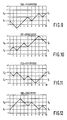
- Figs. 2 to 12 show diagrams which give the instantaneous digital sum values of a code word as a function of the bit number.
- the words are 10-bit code words with the most significant bits at position 1.
- the digital sum value which ranges from +3 to -2 has been plotted vertically. Thus, six digital sum values are possible.
- the code words are given both in binary representation and in decimal representation.
- disparity +2 means decoding from the initial state So
- disparity -2 means decoding from the initial state S l
- disparity 0 means decoding regardless of the initial state.
- the up/down counter 15 Fig. 1 merely serves to determine the disparity of the word received. This does not give rise to error propagation when an erroneous initial state is detected. Indeed, the initial state of each word is determined independently of its history. It is then possible to incorporate one table in the decoding circuit, for example the table corresponding to the initial state So, the words being converted after inversion and reversal when the disparity is -2 and directly when the disparity is +2 or 0.
- Fig. 11 shows an example of such a word ending with three zeros (initial state So)
- Fig. 12 shows an example of the word after reversal (initial state S i ).
- the initial state can be determined simply from the fact that the word begins (initial state S 1 ) or ends (initial state So) with three zeros whilst the disparity is zero.
- the first group To is formed by the input words O ⁇ i ⁇ 88, the second group T 1 by the input words 89 ⁇ i ⁇ 243, and the third group T 2 by the words 244 ⁇ i ⁇ 255.
- a sequence number is assigned to all the output code words with said disparity.
- the series of sequence numbers is uninterrupted, so that an unambiguous code word conversion can be obtained by relating the 8-bit input words to the sequence numbers in conformity with their binary weights.
- this encoding and decoding method is not possible. Indeed, some of the words of the series of 10-bit output code words to which sequence numbers have been assigned via the Pascal triangle are not permissible.
- the permissible 10-bit code words cannot be provided with an uninterrupted series of sequence numbers by means of the Pascal triangle, so that the 8-bit input words cannot be mapped onto the 10-bit output code words in conformity with their sequence numbers, which depend on their binary weights, via the Pascal triangle, or the other way round.
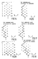
- a modified Pascal triangle is used in conformity with the rules described with reference to Fig. 14, this is found to be possible again.
- Fig. 14 shows an example of such a modified Pascal triangle obtained in conformity with the following general rules:
- the encoding method proceeds as follows: the sequence number of the input word is compared with the starting number (55). If this sequence number is higher or equal the starting number is subtracted from it and the vector "1" is followed to the number situated diagonally above it to the right, whilst a logic one is supplied. If the sequence number is smaller, the method proceeds directly to the next sequence number at the top left, whilst a logic zero is supplied. This operation is repeated for every following number until eventually the asterisk is reached.
- the method is reversed. Starting is effected at the starting number (55). Upon receipt of a logic one the diagonal to the top right is followed and the number is accumulated; upon receipt of logic zero the diagonal to the top left is followed without said number being accumulated. At every position the same operation is carried out until the asterisk is reached, the number obtained by accumulation constituting the sequence number of the word obtained by decoding. In practice, the binary weight of this word will be chosen as the sequence number, which is effected directly by adding the numbers of the modified Pascal triangle as binary numbers.
- Fig. 15 shows a first example to illustrate the operation of the encoding and decoding method.
- the selected input word is the 8-bit word 00000000 with the decimal sequence number 0.
- the number 55 cannot be subtracted from this sequence number, so that it is necassary to step to the top left to the number 21, a logic 0 being supplied.
- the number 21 cannot be subtracted, so that again it is necessaryto step to the to the top left and to supply a logic 0, so that the number is reached.
- Starting is effected at the number 55. This is higher than 29, so that a step is made to the top left to the number 21 and a zero is supplied.
- the next number (21) is higher, so that a logic zero is supplied and a step is made to the top left.
- the number then found (8) can be subtracted, so that zero remains.
- a step to the top right is made and a logic one is supplied.
- the method procceeds in this way until the asterisk is reached.
- the complete output word is then 0101001011 (331 in the table of Fig. 13).
- Fig. 18 illustrates how a modified Pascal triangle for decoding the group T 1 is obtained.
- the initial state S 1 has been selected.
- the group having the initial state So is then obtained by reversal plus inversion.
- the digital-sum-value variation within the word is then +1 and -4, so that six columns are required, using the 5th column as the starting column.
- the variation would be between +3 and -2, so that again six columns would be required with the third column as the starting column.
- the disparity from S 1 is -2, so that the third column is found as the end column (see asterisk) (in the complementary case the 5th column would be found as the end column).
- the fourth column first row the number one is entered and a zero at any other relevant position in said row. Further, the matrix is filled in accordance with the rules, the non-relevant numbers being parenthesized (and being omitted in Fig. 19).
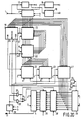
- Fig. 20 shows an example of an encoding circuit which employs the principles described with reference to the foregoing Figures.
- a serial 8-bit signal on input 1 is converted into a 8-bit parallel signal by means of a series-to-parallel converter 2.
- a word-synchronous clock signal c is generated by means of a clock-signal generator 16 and an 8-bit synchronous clock signal a is generated by means of a clock-signal generator 17.
- a clock signal b which is in synchronism with the bit frequency of the output signal to be formed, i.e. a frequency which is 10/8 times the frequency of the clock signals a, is formed by means of the clock-signal generator 18, which clock signals are applied to the various parts of the encoding circuit for synchronizing purposes.
- the 8-bit output of the series-to-parallel converter 2 is connected to a group-decoder circuit 19 which generates a signal To, T 1 or T 2 , for example by means of logic gates, when the binary weight i of the 8-bit word complies with i ⁇ 89; 89--i--243, and i>243 respectively; these are the three previously defined groups of input words which are each encoded in a separate manner.
- the arrangement further comprises a memory 20 which is switched on by the signal To and which contains the modified Pascal triangle shown in Fig. 14, which memory is arranged in parallel with a memory 21 which can be switched on by the signal T 1 and which contains the modified Pascal triangle shown in Fig. 18.
- the outputs of the two memories are connected to a subtractor circuit 22, which subtracts the number supplied by the memory 20 or 21 from the number supplied by an accumulator 23.
- the output of the subtractor circuit is also connected to the accumulator 23.
- the input word received from the series-to-parallel converter 2 is loaded into the accumulator 23 under command of the clock signal c.
- the memories 20 and 21 are row-addressed by the bit clock signal a, causing a shift by a one row after every bit in such a way that the modified Pascal triangle (Figs. 14, 18) is stepped through from bottom to top.
- the modified Pascal triangle Figs. 14, 18
- the subtractor circuit 22 determines the column addresses of the memories via an upldown counter which decrements the column number by one when said overflow signal appears (or the number in the memory cannot be subtracted) and which increments the column number by one if this signal does not occur (or the number in the memory can be subtracted from the number in the accumulator).
- the inverted overflow signal then also constitutes the dssired output signal.
- this number is a logic one when the number can be subtracted from the number in the accumulator and a logic zero when the number cannot be subtracted.
- the initial sequence number may be subtracted when the input signal is loaded into the accumulator 23 under command of the signal T 1 or allowance may be made for this in the numbers contained in the memory 21 (in a manner as described with reference to Fig. 19).
- the inverted overflow signal is converted into a 10-bit parallel signal (using the clock signal b).
- the apparatus further comprises a memory circuit 27 which receives the 8-bit parallel input word from the series-to-parallel converter 2, which is energized by the signal T 2 , and which contains the code words of said third group T 2 , so that under command of the signal T 2 the 10-bit code words of the third group are generated as a function of the relevant 8-bit input words.
- Said 10- bit words which are available in parallel form, are applied to the output of the series-to-parallel converter 26 via a wired-or, so that on this output all the 10-bit code words appear in the rhythm of the 8-bit input words but all encoded in conformity with the initial state S I .
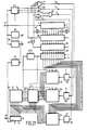
- Fig. 21 shows a decoding circuit for decoding 10 - bit.words which have been encoded by means of the encoding circuit shown in Fig. 20.
- the 10-bit words are applied to the series-to-parallel converter 7 as a serial bit stream to be converted into a 10-bit parallel bit stream.
- clock-generator circuits 35, 36 and 37 the clock signals c, b, and a, respectively are generated, which signals are synchronous with the word frequency, the bit frequency of the 10-bit words, and the bit frequency of the 8-bit words, respectively.
- the 10-bit words are applied to an up/down counter 41, which is synchronized by the word-clock signal c and at the end of every word indicates the disparity (the digital-sum-value variation within said word). This may be -2, +2 or 0.
- the three least significant bits of the output signal of the series-to-parallel converter 7 are monitored by the AND-gate 42 and the three most significant bits are monitored by the AND-gate 43, both gates having inverting inputs which supply a signal when the relevant bits are zero, i.e. in the state So and S l , respectively in the case of a word of group T 2 .
- the word belongs to group T 2 .
- the output signals of gates 42 and 43 are combined with the OR-gate 44 and the output signal of this OR-gate is combined with the 0- disparity output signal of the counter 41 in AND-gate 45 to form a signal which identifies a word of group T 2 .
- OR-gate 46 combines the +2 disparity output signal of counter 41 and the -2 disparity output signal to form a signal which identifies a word of group T 1 , which words have a disparity of ⁇ 2.
- the 0 disparity signal from counter 41 is an indicative of the group To when gates 42 and 43 do not supply an output signal, which is detected by means of gate 47, which consequently supplies a signal which identifies a word of group To.
- the decoding circuit shown in Fig. 21 starts from the state S 1 and words in the state S 1 are converted by inversion and/or reversal.
- Words of group T 1 in the state So can be identified in that they have -2 disparity, so that in the case of -2 disparity it is necessary to invert and reverse.
- Words of groups T 2 in the state So can be identified from the fact that the three least significant bits are zero, i.e. from the fact that gate 42 supplies an output signal.
- the output signal of the series-to-parallel converter 7 is applied to a switchable reversing circuit 39 via a switchable inverter circuit 38.
- the inverter circuit 38 is switched on by the -2 disparity signal from counter 42 and the reversing circuit 39 by a signal formed by combining this -2 disparity signal and the gate 42 output signal by means of OR-gate 48, synchronization being effected by means of the word clock signal c.
- the circuit shown in Fig. 21 comprises a memory 49 which stores the modified Pascal triangle shown in Fig. 14, which is switched on by means of the signal To and which is arranged in parallel with a memory circuit 50 which stores the modified Pascal triangle shown in Fig. 8 and which is switched on by the signal T 1 .
- the memory circuits 49 and 50 are row-addressed by the bit-clock signal b in such a way that at the beginning of the word starting is effected at a row which corresponds to the 10th row of the Pascal triangle, which row is stepped through from bottom to top.
- These memory circuits are column-addressed by an up/down counter 510 which receives the 10-bit words via a parallel-to-series converter 40 and consequently generates the instantaneous digital sum value within the word, in such a way that starting is effected in the specified starting column, i.e. the third column for the memory 49 and the fifth column for the memory 50, to proceed to a column of higher sequence number after every logic one.
- a start to a higher row is effected so that a step to the top right in the modified Pascal triangle is made in the same way as described with reference to Figs. 14 to 19. Similarly, a logic zero results in a step to the top left.
- the numbers in the modified Pascal triangle must be accumulated when a logic one occurs in the word.
- the circuit comprises an accumulator 51 and an adder circuit 52 which is controlled by the word on the output of the parallel-to-series converter 52 and, each time that a logic one occurs in said word, adds the contents of the instantaneously addressed memory location to the accumulator contents, synchronized in such a way that the number is read out of the memory before the address is changed under command of the same logic one.
- the output word is generated as an 8-bit code word in the accumulator 51, which transfers its contents to the parallel-to-series converter 9 at the end of said word and is then reset.
- the shift over 89 of the words of group T 1 may then be effected by, for example, resetting the accumulator 51 to 89 at the end of every word or by adapting the contents of the memory 50.
- the words on the output of the reversing circuit 39 are applied in parallel to a memory 53 which is switched on by the signal T 1 and which as a function thereof generates the 8-bit words by reading out a table, which words together with the output words of the accumulator 51 are applied to the parallel-to-series converter 9 via a wired OR, after which they are applied to the output 10, said converter being controlled by the clock signals a and c.
- Synchronization must be effected by means of the clock signals a, b and c and, if required, by means of delay networks and hold circuits.
- a 10-bit word is subject to a delay of one full word during its processing via the series to parallel converter, the inverting circuit, the reversing circuit 30, and the parallel-to series converter 40, so that the generated signals To, T 1 and T 2 should be transferred via gates 54, 55 and 56 with a delay of one word length.
- a memory circuit is required for each of the three groups To, T 1 and T 2 , which may be undesirable because of the required storage capacity.
- Words having instantaneous digital sum values of -4 cannot be mapped directly to the state So because they would reach the impermissible level 4 owing to inversion in the state So.
- the levels -2, -1, 0 and +1 occur, as well as the level +3 owing to the inversion described above.
- those code words which reach the level +3 without having reached the level +2 are missing.
- These code words may then be mapped, for example, by "folding" the word about the level +2 after inversion, for example by an additional inversion of the bits which follow when the +2 level is reached and by applying an additional inversion (in order to cancel the previous inversion when this level is reached a second time etc.
- the group of code words thus found can then be encoded and decoded by means of a modified Pascal triangle having six columns. Since for the encoding and decoding of the group T 1 also a modified Pascal triangle having six columns is required, it is effective to combine the two, which is found to be possible when two end columns are employed. In that case a starting column is selected (5th column corresponding to the state S 1 ; see also Fig. 18 and the description), an end column for words of zero dispartiy, i.e. the fifth column, and an end column for words of -2 disparity, i.e. the third column.
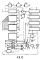
- Fig. 29 shows an example of an encoding circuit based on the modified Pascal triangle of Fig. 26. Its principle corresponds to that of the circuit of Fig. 20 but in the present example only one memory 21, in which the modified Pascal triangle of Fig. 26 is stored, is used which is employed in conformity with Fig. 26, in which the inverting circuit 28 in the reversing circuit 29 are controlled differently as a function of the code words, and in which an inverter 60 is arranged between the parallel-to-series converter 4 and the output 11 in order to effect the "folding" about 2 described with reference to Fig. 25.
- the generated code word which becomes available as the overflow signal of the subtractor circuit 22 after inversion with the inverter 25, is applied to the up/down counter 24 to control the column addressing of the memory 21.
- the output signal is also applied to gate circuits with a latching function (flip-flops) 61 and 62, which detect whether said up/down counter is in a -3 state and a -4 state, respectively.
- This output signal is also applied to a hold circuit 63 in order to hold the state of the counter at the end of the word (the disparity).
- the disparity is detected by gates 64 and 65 with a latching function, which detect the states 0 and -2.
- the initial state (So or S 1 ) is detected by means of the upl down counter 31.
- AND-gate 66 the output signals of the gates 61, 64 and 31 are combined, which AND-gate therefore supplies an output signal which indicative of a word which has reached or passed the level -3 whilst the disparity of this word is 0 and the state So. Such a word should then be inverted.
- the signals from the gate 65 and the counter 31 are combined by means of the AND-gate 67 which supplies a signal which is indicative of words of -2 disparity in the state So, i.e. words which must be inverted and reversed.
- the output signal of gate 67 is applied to the reversing circuit 29 and, after combination with the output signal of gate 66 by means of an OR-gate 68, also to the inverting circuit 28.
- the signals from gates 62 and 64 and from the counter 31 are combined by means of an AND-gate 90.
- This AND-gate supplies a signal which is indicative of words of zero disparity which reach the level -4 whilst the initial state is So. These words have to be folded about +2. This can be effected by means of the inverter 60.
- the bit series has a delay of one word length relative to the bit series on the input of converter 26. Therefore, the signal from gate 67 is delayed by one word length with the hold circuit 69.
- the digital-sum-value variation within each word of the output signal of the converter 4 is determined by means of an upl down counter 71 and each time that the level +2 is reached a signal is supplied.
- this signal is combined with the output signal of the hold circuit 69.
- This AND-gate 72 controls a flip-flop 70 which changes over each time that the -2 level is reached during a word to be folded. This flip-flop controls the inverter 60, to obtain the desired folding about +2.
- Fig. 30 shows an example of a decoder circuit for decoding words which have been encoded by means of the circuit shown in Fig. 29.
- the principle of this encoding circuit corresponds to that of the circuit shown in Fig. 21 but now only one memory circuit 50 is employed which stores the modified Pascal triangle shown in Fig. 26 and the inverting circuit and the reversing circuit are controlled differently as a function of the input signal.
- the input signal is applied to an up/down counter 73.
- the output signal of this counter is applied to gates 74 and 75 with a hold functions in order to detect the counts +2 and +3, and also to a hold switch 76 which holds the final count of said counter at the end of every word, the gates 77 and 78, which have hold functions, detecting whether this final count is zero and +2, respectively.
- the output signals of gates 74 and 77 are combined with AND-gate 79, yielding a signal which is indicative of words of zero disparity which reach the +3 level.
- the output signals of gates 75 and 77 are combined by means of the AND-gate 80. This gate 80 supplies a signal which is indicative of words of zero disparity which reach or pass the +2 level, i.e.
- the output signal of the series-to-parallel converter 40 is monitored by means of the up/down counter 84 to supply a signal each time that the count +2 is reached within a word, which output signal is combined with the signal from the hold circuit 82 by means of the AND-gate 85 and is subsequently applied to the flip-flop 86 which changes over an inverter 87 arranged between the converter 40 and the adder 52.
- the word-synchronizing signal c generator 35 in Figs. 21 and 30
- steps may be taken to ensure that this signal remains in phase with the data words by adding synchronizing word which are unique within the sequence of code words and which cannot be derived from adjoining parts of consecutive code words.
- it may be necessary, for example in the Table shown in Fig. 13, to inhibit a number of code words.
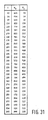
- the table of Fig. 31 shows those information words (i) of the table of Fig. 13 which have been modified to enable the use of the synchronizing words 0100111110 and 0000111110.
Landscapes
- Engineering & Computer Science (AREA)
- Signal Processing (AREA)
- Physics & Mathematics (AREA)
- Spectroscopy & Molecular Physics (AREA)
- Computer Networks & Wireless Communication (AREA)
- Compression, Expansion, Code Conversion, And Decoders (AREA)
- Dc Digital Transmission (AREA)
- Executing Machine-Instructions (AREA)
- Signal Processing For Digital Recording And Reproducing (AREA)
- Analogue/Digital Conversion (AREA)
Priority Applications (1)
| Application Number | Priority Date | Filing Date | Title |
|---|---|---|---|
| AT85200048T ATE53727T1 (de) | 1984-01-20 | 1985-01-18 | Anordnung zur kodierung von n-bits-informationen in ein m-bit-kodewoerter anordnung zur dekodierung von m-bits-kodeworten in n-bits- informationsworten. |
Applications Claiming Priority (4)
| Application Number | Priority Date | Filing Date | Title |
|---|---|---|---|
| NL8400187A NL8400187A (nl) | 1984-01-20 | 1984-01-20 | Systeem voor het coderen en decoderen van een digitale datastroom. |
| NL8400187 | 1984-08-08 | ||
| NL8402445 | 1984-08-08 | ||
| NL8402445A NL8402445A (nl) | 1984-01-20 | 1984-08-08 | Werkwijze voor het coderen van n-bits informatiewoorden naar m-bits codewoorden, inrichting voor het uitvoeren van die werkwijze, werkwijze voor het decoderen van m-bits codewoorden naar n-bits informatiewoorden en inrichting voor het uitvoeren van die werkwijze. |
Publications (3)
| Publication Number | Publication Date |
|---|---|
| EP0150083A2 EP0150083A2 (en) | 1985-07-31 |
| EP0150083A3 EP0150083A3 (en) | 1987-03-11 |
| EP0150083B1 true EP0150083B1 (en) | 1990-06-13 |
Family
ID=26645923
Family Applications (1)
| Application Number | Title | Priority Date | Filing Date |
|---|---|---|---|
| EP85200048A Expired EP0150083B1 (en) | 1984-01-20 | 1985-01-18 | Apparatus for encoding n-bit information words into m-bit code words, apparatus for decoding m-bit code words into n-bit information words |
Country Status (13)
| Country | Link |
|---|---|
| US (1) | US4573034A (da) |
| EP (1) | EP0150083B1 (da) |
| AT (1) | ATE53727T1 (da) |
| AU (1) | AU596922B2 (da) |
| BR (1) | BR8500200A (da) |
| CA (1) | CA1271846A (da) |
| CS (1) | CS277290B6 (da) |
| DE (1) | DE3578288D1 (da) |
| DK (1) | DK21385A (da) |
| NL (1) | NL8402445A (da) |
| NO (1) | NO850200L (da) |
| NZ (1) | NZ210859A (da) |
| YU (2) | YU6785A (da) |
Families Citing this family (36)
| Publication number | Priority date | Publication date | Assignee | Title |
|---|---|---|---|---|
| US4618187A (en) * | 1983-04-15 | 1986-10-21 | Yamaha Hatsudoki Kabushiki Kaisha | Wire wheel |
| NL8402444A (nl) * | 1984-01-20 | 1986-03-03 | Philips Nv | Werkwijze voor het overdragen van informatie, codeerinrichting voor toepassing in de werkwijze en decodeerinrichting voor toepassing in de werkwijze. |
| NL8400212A (nl) * | 1984-01-24 | 1985-08-16 | Philips Nv | Werkwijze voor het coderen van een stroom van databits, inrichting voor het uitvoeren van de werkwijze en inrichting voor het decoderen van de volgens de werkwijze verkregen stroom kanaalbits. |
| JPS60174301A (ja) * | 1984-02-20 | 1985-09-07 | Yamaha Motor Co Ltd | ワイヤスポ−ク車輪 |
| NL8403078A (nl) * | 1984-10-10 | 1986-05-01 | Philips Nv | Werkwijze voor het overdragen van informatie, codeerinrichting voor toepassing in de werkwijze en decodeerinrichting voor toepassing in de werkwijze. |
| BE904913A (nl) * | 1986-06-13 | 1986-12-15 | Bell Telephone Mfg | Data overdrachtsysteem. |
| JPS63284930A (ja) * | 1987-05-15 | 1988-11-22 | Fujitsu Ltd | mBnB符号変換回路 |
| US5016258A (en) * | 1988-06-10 | 1991-05-14 | Matsushita Electric Industrial Co., Ltd. | Digital modulator and demodulator |
| US5237701A (en) * | 1989-03-31 | 1993-08-17 | Ampex Systems Corporation | Data unpacker using a pack ratio control signal for unpacked parallel fixed m-bit width into parallel variable n-bit width word |
| GB8912471D0 (en) * | 1989-05-31 | 1989-07-19 | Int Computers Ltd | Data transmission code |
| US6289308B1 (en) | 1990-06-01 | 2001-09-11 | U.S. Philips Corporation | Encoded wideband digital transmission signal and record carrier recorded with such a signal |
| US5136290A (en) * | 1990-06-18 | 1992-08-04 | Bond James W | Message expansion decoder and decoding method for a communication channel |
| US5034742A (en) * | 1990-06-19 | 1991-07-23 | The United States Of America As Represented By The Secretary Of The Navy | Message compression encoder and encoding method for a communication channel |
| US5208834A (en) * | 1991-03-15 | 1993-05-04 | International Business Machines Corporation | Lexicographical encoding and decoding of state-dependent codes |
| JP3541439B2 (ja) * | 1994-07-08 | 2004-07-14 | ソニー株式会社 | 信号変調方法及び装置、並びに信号復調装置及び方法 |
| WO1996013905A1 (en) * | 1994-10-31 | 1996-05-09 | Philips Electronics N.V. | Digital transmission and recording system with simple error correction |
| US5699062A (en) * | 1995-02-01 | 1997-12-16 | International Business Machines Corporation | Transmission code having local parity |
| KR0155824B1 (ko) * | 1995-05-29 | 1998-12-15 | 김광호 | 디지탈신호 기록장치 |
| EP1292079A3 (en) * | 1995-08-03 | 2004-09-29 | Seagate Technology LLC | Partial response encoder and decoder |
| JPH11511283A (ja) * | 1995-08-03 | 1999-09-28 | シーゲート テクノロジー,インコーポレイテッド | 整合スペクトルヌルエンコーダ/デコーダ |
| US5790057A (en) * | 1996-08-12 | 1998-08-04 | Lanart Corporation | Method of and system for the efficient encoding of data |
| US6111834A (en) * | 1997-08-11 | 2000-08-29 | Seagate Technology, Inc. | Data storage system having efficient block code implementation |
| US6265994B1 (en) * | 1998-01-09 | 2001-07-24 | U.S. Philips Corporation | Device for encoding/decoding n-bit source words into corresponding m-bit channel words, and vice versa |
| JP3991348B2 (ja) * | 1998-10-02 | 2007-10-17 | ソニー株式会社 | 符号化装置および方法、復号装置および方法、並びに記録媒体 |
| US6438728B1 (en) * | 1999-12-15 | 2002-08-20 | Intel Corporation | Error character generation |
| US6661355B2 (en) * | 2000-12-27 | 2003-12-09 | Apple Computer, Inc. | Methods and apparatus for constant-weight encoding & decoding |
| US6624770B1 (en) | 2001-12-13 | 2003-09-23 | Cisco Technology, Inc. | Block coding system and method of data aggregation |
| EP1341160A1 (en) * | 2002-03-01 | 2003-09-03 | Deutsche Thomson-Brandt Gmbh | Method and apparatus for encoding and for decoding a digital information signal |
| US7177864B2 (en) * | 2002-05-09 | 2007-02-13 | Gibraltar Analytics, Inc. | Method and system for data processing for pattern detection |
| US6748328B2 (en) * | 2002-06-10 | 2004-06-08 | Halliburton Energy Services, Inc. | Determining fluid composition from fluid properties |
| TWI234374B (en) * | 2003-03-04 | 2005-06-11 | Realtek Semiconductor Corp | Spread spectrum encoding method and spread spectrum encoding modulation method |
| US7307554B2 (en) * | 2004-12-20 | 2007-12-11 | Kawasaki Microelectronics, Inc. | Parallel data transmission method and parallel data transmission system |
| DE102007053311A1 (de) | 2007-06-21 | 2008-12-24 | Robert Bosch Gmbh | Ansteuersystem für ein Roboterfahrzeug |
| JP5742506B2 (ja) * | 2011-06-27 | 2015-07-01 | 日本電気株式会社 | 文書類似度算出装置 |
| US9966970B2 (en) | 2015-04-09 | 2018-05-08 | Oracle International Corporation | Efficient silent code assignment to a set of logical codes |
| US11115250B1 (en) * | 2019-03-01 | 2021-09-07 | Acacia Communications, Inc. | MPPM encoder and decoder |
Family Cites Families (7)
| Publication number | Priority date | Publication date | Assignee | Title |
|---|---|---|---|---|
| US3387366A (en) * | 1967-03-28 | 1968-06-11 | Agway Inc | Film slitter |
| GB1540617A (en) * | 1968-12-13 | 1979-02-14 | Post Office | Transformation of binary coded signals into a form having lower disparity |
| JPS5619506A (en) * | 1979-07-23 | 1981-02-24 | Sony Corp | Code converting method |
| US4408189A (en) * | 1981-05-18 | 1983-10-04 | Northern Telecom Limited | Method and apparatus for code conversion of binary to multilevel signals |
| US4486739A (en) * | 1982-06-30 | 1984-12-04 | International Business Machines Corporation | Byte oriented DC balanced (0,4) 8B/10B partitioned block transmission code |
| US4486784A (en) * | 1982-12-27 | 1984-12-04 | International Business Machines Corporation | Image compression systems |
| NL8402444A (nl) * | 1984-01-20 | 1986-03-03 | Philips Nv | Werkwijze voor het overdragen van informatie, codeerinrichting voor toepassing in de werkwijze en decodeerinrichting voor toepassing in de werkwijze. |
-
1984
- 1984-08-08 NL NL8402445A patent/NL8402445A/nl not_active Application Discontinuation
- 1984-11-29 US US06/676,467 patent/US4573034A/en not_active Expired - Fee Related
-
1985
- 1985-01-17 YU YU00067/85A patent/YU6785A/xx unknown
- 1985-01-17 CA CA000472282A patent/CA1271846A/en not_active Expired
- 1985-01-17 NO NO850200A patent/NO850200L/no unknown
- 1985-01-17 BR BR8500200A patent/BR8500200A/pt unknown
- 1985-01-17 NZ NZ210859A patent/NZ210859A/xx unknown
- 1985-01-17 DK DK21385A patent/DK21385A/da not_active Application Discontinuation
- 1985-01-18 CS CS85376A patent/CS277290B6/cs unknown
- 1985-01-18 EP EP85200048A patent/EP0150083B1/en not_active Expired
- 1985-01-18 AT AT85200048T patent/ATE53727T1/de not_active IP Right Cessation
- 1985-01-18 AU AU37923/85A patent/AU596922B2/en not_active Ceased
- 1985-01-18 DE DE8585200048T patent/DE3578288D1/de not_active Expired - Lifetime
-
1987
- 1987-04-07 YU YU00621/87A patent/YU62187A/xx unknown
Also Published As
| Publication number | Publication date |
|---|---|
| CS277290B6 (en) | 1993-01-13 |
| DK21385D0 (da) | 1985-01-17 |
| DK21385A (da) | 1985-07-21 |
| ATE53727T1 (de) | 1990-06-15 |
| NZ210859A (en) | 1989-01-06 |
| AU596922B2 (en) | 1990-05-17 |
| BR8500200A (pt) | 1985-08-27 |
| EP0150083A2 (en) | 1985-07-31 |
| CS37685A3 (en) | 1992-05-13 |
| YU6785A (en) | 1987-10-31 |
| NL8402445A (nl) | 1985-08-16 |
| NO850200L (no) | 1985-07-22 |
| AU3792385A (en) | 1985-07-25 |
| US4573034A (en) | 1986-02-25 |
| CA1271846A (en) | 1990-07-17 |
| YU62187A (en) | 1989-12-31 |
| DE3578288D1 (de) | 1990-07-19 |
| EP0150083A3 (en) | 1987-03-11 |
Similar Documents
| Publication | Publication Date | Title |
|---|---|---|
| EP0150083B1 (en) | Apparatus for encoding n-bit information words into m-bit code words, apparatus for decoding m-bit code words into n-bit information words | |
| US4620311A (en) | Method of transmitting information, encoding device for use in the method, and decoding device for use in the method | |
| US4502143A (en) | Consecutive identical digit suppression system in a digital communication system | |
| US5047767A (en) | Apparatus utilizing a four state encoder for encoding and decoding A sliding block (1,7) code | |
| US5079548A (en) | Data packing circuit in variable length coder | |
| KR860001257B1 (ko) | 데이타 독출회로 | |
| US4394641A (en) | Method and device for coding binary data and a device decoding coded data | |
| US5508701A (en) | Data conversion method and recording and reproduction apparatus | |
| US4481648A (en) | Method and system for producing a synchronous signal from _cyclic-redundancy-coded digital data blocks | |
| KR950006085B1 (ko) | 부호변조장치 | |
| EP0390309B1 (en) | Data unpacker | |
| EP0954861A1 (en) | Device for encoding/decoding n-bit source words into corresponding m-bit channel words, and vice versa | |
| US5295163A (en) | Synchronization method for a run length-limited (1,7)-code, and circuit arrangement for said method | |
| US4543559A (en) | Generator of encoding or decoding 8-bit bytes which can be used in a video system | |
| CA1171536A (en) | Device for interrogating and correcting a serial data signal | |
| KR20020011981A (ko) | 정보 코딩을 위한 장치 및 방법과, 그 코딩된 정보를디코딩하기 위한 장치 및 방법과, 변조신호 및 기록매체제조방법 | |
| US5278845A (en) | Teletext decoder with error detection and correction | |
| US6477209B1 (en) | Method for encoding and decoding recording codes and method for inserting synchronization signals | |
| JPS63313945A (ja) | ディジタル符号復号装置 | |
| KR100752880B1 (ko) | 정보를 코딩/디코딩하는 방법 및 장치 | |
| KR950011290B1 (ko) | 어드레스 발생회로 | |
| NL8400187A (nl) | Systeem voor het coderen en decoderen van een digitale datastroom. | |
| JPH0787371B2 (ja) | 並列型a/d変換器 | |
| EP0484072A2 (en) | Apparatus and method for binary data encoding and decoding | |
| KR20010074694A (ko) | 복수의 채널어로 구성된 직렬 데이터 스트림을 복수의정보어로 구성된 데이터 스트림으로 디코딩하는 장치 |
Legal Events
| Date | Code | Title | Description |
|---|---|---|---|
| PUAI | Public reference made under article 153(3) epc to a published international application that has entered the european phase |
Free format text: ORIGINAL CODE: 0009012 |
|
| AK | Designated contracting states |
Designated state(s): AT BE CH DE FR GB IT LI SE |
|
| ITCL | It: translation for ep claims filed |
Representative=s name: STUDIO TORTA SOCIETA' SEMPLICE |
|
| PUAL | Search report despatched |
Free format text: ORIGINAL CODE: 0009013 |
|
| AK | Designated contracting states |
Kind code of ref document: A3 Designated state(s): AT BE CH DE FR GB IT LI SE |
|
| 17P | Request for examination filed |
Effective date: 19870515 |
|
| 17Q | First examination report despatched |
Effective date: 19881123 |
|
| GRAA | (expected) grant |
Free format text: ORIGINAL CODE: 0009210 |
|
| AK | Designated contracting states |
Kind code of ref document: B1 Designated state(s): AT BE CH DE FR GB IT LI SE |
|
| PG25 | Lapsed in a contracting state [announced via postgrant information from national office to epo] |
Ref country code: SE Effective date: 19900613 Ref country code: BE Effective date: 19900613 Ref country code: AT Effective date: 19900613 |
|
| REF | Corresponds to: |
Ref document number: 53727 Country of ref document: AT Date of ref document: 19900615 Kind code of ref document: T |
|
| REF | Corresponds to: |
Ref document number: 3578288 Country of ref document: DE Date of ref document: 19900719 |
|
| ITF | It: translation for a ep patent filed | ||
| ET | Fr: translation filed | ||
| PGFP | Annual fee paid to national office [announced via postgrant information from national office to epo] |
Ref country code: GB Payment date: 19901221 Year of fee payment: 7 |
|
| PGFP | Annual fee paid to national office [announced via postgrant information from national office to epo] |
Ref country code: FR Payment date: 19910118 Year of fee payment: 7 |
|
| ITTA | It: last paid annual fee | ||
| PGFP | Annual fee paid to national office [announced via postgrant information from national office to epo] |
Ref country code: DE Payment date: 19910322 Year of fee payment: 7 |
|
| PLBE | No opposition filed within time limit |
Free format text: ORIGINAL CODE: 0009261 |
|
| STAA | Information on the status of an ep patent application or granted ep patent |
Free format text: STATUS: NO OPPOSITION FILED WITHIN TIME LIMIT |
|
| PGFP | Annual fee paid to national office [announced via postgrant information from national office to epo] |
Ref country code: CH Payment date: 19910423 Year of fee payment: 7 |
|
| 26N | No opposition filed | ||
| PG25 | Lapsed in a contracting state [announced via postgrant information from national office to epo] |
Ref country code: GB Effective date: 19920118 |
|
| PG25 | Lapsed in a contracting state [announced via postgrant information from national office to epo] |
Ref country code: LI Effective date: 19920131 Ref country code: CH Effective date: 19920131 |
|
| REG | Reference to a national code |
Ref country code: GB Ref legal event code: PCNP |
|
| PG25 | Lapsed in a contracting state [announced via postgrant information from national office to epo] |
Ref country code: FR Effective date: 19920930 |
|
| REG | Reference to a national code |
Ref country code: CH Ref legal event code: PL |
|
| PG25 | Lapsed in a contracting state [announced via postgrant information from national office to epo] |
Ref country code: DE Effective date: 19921001 |
|
| REG | Reference to a national code |
Ref country code: FR Ref legal event code: ST |