EP0149385A2 - Window mounting device for oven door - Google Patents
Window mounting device for oven door Download PDFInfo
- Publication number
- EP0149385A2 EP0149385A2 EP84402574A EP84402574A EP0149385A2 EP 0149385 A2 EP0149385 A2 EP 0149385A2 EP 84402574 A EP84402574 A EP 84402574A EP 84402574 A EP84402574 A EP 84402574A EP 0149385 A2 EP0149385 A2 EP 0149385A2
- Authority
- EP
- European Patent Office
- Prior art keywords
- door
- window
- oven
- opening
- seal
- Prior art date
- Legal status (The legal status is an assumption and is not a legal conclusion. Google has not performed a legal analysis and makes no representation as to the accuracy of the status listed.)
- Granted
Links
Images

Classifications
-
- F—MECHANICAL ENGINEERING; LIGHTING; HEATING; WEAPONS; BLASTING
- F24—HEATING; RANGES; VENTILATING
- F24C—DOMESTIC STOVES OR RANGES ; DETAILS OF DOMESTIC STOVES OR RANGES, OF GENERAL APPLICATION
- F24C15/00—Details
- F24C15/02—Doors specially adapted for stoves or ranges
- F24C15/04—Doors specially adapted for stoves or ranges with transparent panels
Definitions
- the present invention relates to a door system with glass adaptable to various types of ovens, used in particular in the food industry, for baking, for example. It constitutes a new conception and realization of the mounting of the glass on the oven door.
- the present invention proposes to overcome these problems by presenting a new device for mounting the glass on the oven door.
- the window according to the invention is fixed to the internal face of the oven door, without being attached thereto, by means of spacers and any fixing means (screws, bolts, etc.). Said window is therefore located at a certain distance from the oven door and is preferably parallel thereto. Ansi is there contact between these two elements (door and window) only through these only spacers.
- the window is supported when the door is closed on a joint attached to the oven.
- the spacers are located relative to the opening of the oven inside or preferably outside of this seal ensuring the seal and on which the glass is supported.
- the cleaning of the window is easy because only its internal part, without roughness is to be cleaned.
- Figure 1 is a cross-sectional view of an embodiment of an oven door on which is mounted a window according to the invention.
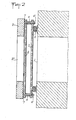
- Figure 2 is a cross-sectional view of another embodiment of an oven door having two panes.
- Figure 1 there is shown in 1, the opening of the oven, in 2, the glass, in 3 the metal door of this oven, which itself has an opening 3 '.
- the window 2 is fixed to the door 3 by means of four spacers 4, at the four corners of the door.
- the oven is closed by pressing said window 2 on the seal 5 which is preferably fixed around the opening 1 of the oven.
- the spacers 4 inside which a passage has been made, used to secure said window 2 with said door 3 by a screw or bolt device 4 ′, are outside the seal 5 relative to the opening of the oven .
- the spacers 4 can be located inside the seal 5 relative to the opening of the oven.
- FIG. 2 there is shown a door 3, on which is fixed a first window 6 with interposition of a spacer 7 between the window and the inner face of the door.
- a second window 2 is fixed to the screws 4 'integral with the door with the interposition of spacers 4 at a certain distance from the internal face of the door 3 and from the first window 6.
- the second window 2 cooperates with a surrounding seal 5 the opening of the oven 1 to ensure the closing thereof.
- the first window 6 is fixed near or against the internal face of the door.
- an air circulation is established between: panes 2 and 6.
Landscapes
- Engineering & Computer Science (AREA)
- Chemical & Material Sciences (AREA)
- Combustion & Propulsion (AREA)
- Mechanical Engineering (AREA)
- General Engineering & Computer Science (AREA)
- Electric Ovens (AREA)
- Constitution Of High-Frequency Heating (AREA)
- Joining Of Glass To Other Materials (AREA)
- Mirrors, Picture Frames, Photograph Stands, And Related Fastening Devices (AREA)
- Special Wing (AREA)
Abstract
Dispositif de montage d'une vitre pour porte de four. La vitre (2) est à une certaine distance de la face interne de la porte (3) et est fixée à celle-ci ; la face interne de ladite vitre (2) coopérant avec un joint (5) entourant l'ouverture du four (1) pour assurer la fermeture de ce dernier.Glass door mounting device for oven door. The window (2) is at a certain distance from the internal face of the door (3) and is fixed to the latter; the inner face of said window (2) cooperating with a seal (5) surrounding the opening of the oven (1) to ensure the closing of the latter.
L'invention est utilisée pourla réalisation de fours.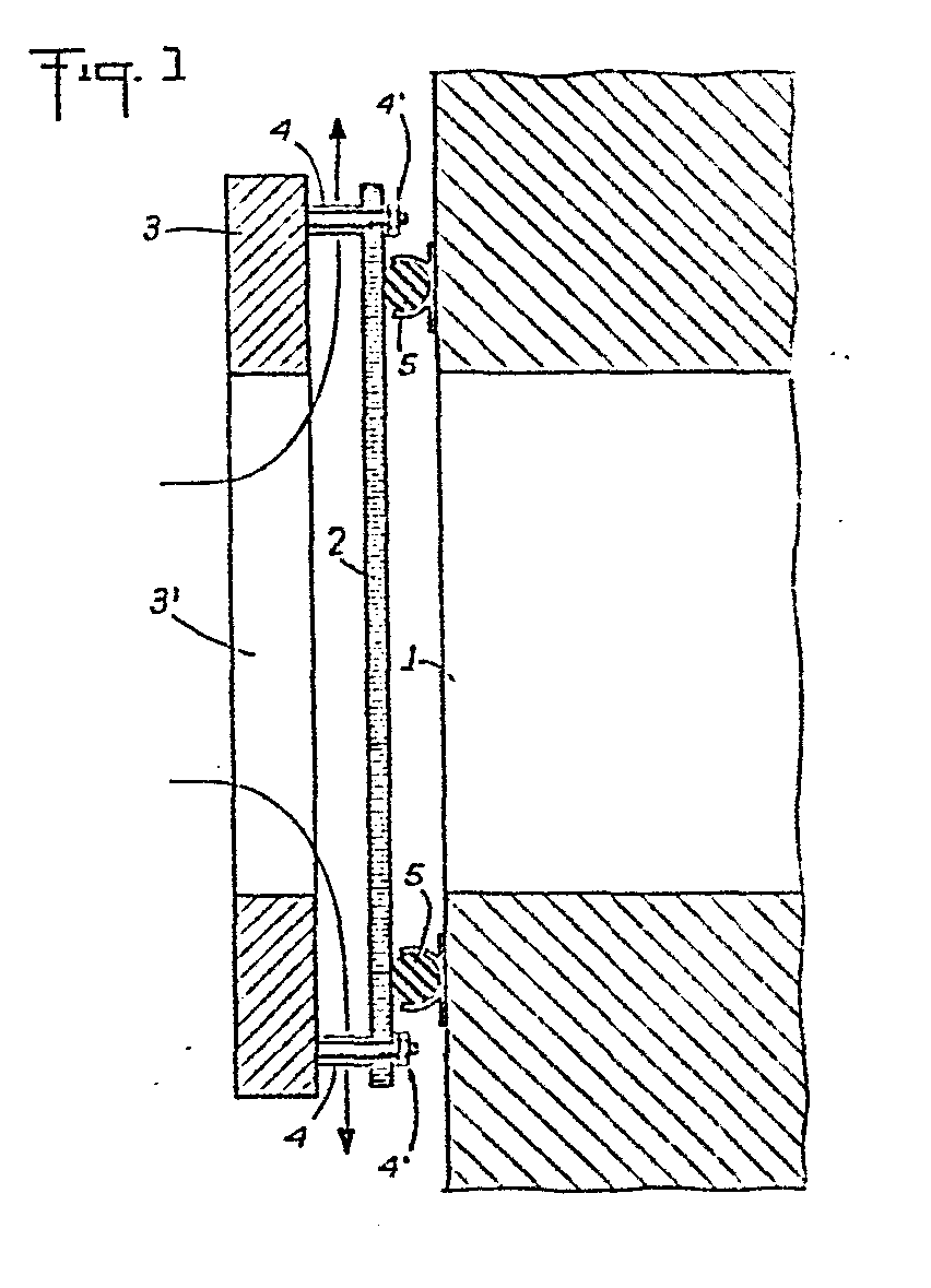
Description
La présente invention concerne un système de porte avec vitre adaptable sur divers types de fours, employés notamment dans l'industrie alimentaire, pour la pa- tisserie par exemple. Elle constitue une conception et une réalisation nouvelle du montage de la vitre sur la porte du four.The present invention relates to a door system with glass adaptable to various types of ovens, used in particular in the food industry, for baking, for example. It constitutes a new conception and realization of the mounting of the glass on the oven door.
Les systèmes actuels de porte sur les fours comportent une vitre fixée au contact de la face interne de ladite porte, l'étanchéité de cette vitre étant faite à l'aide de joints, dits joints de vitre.Current door systems on ovens include a window fixed in contact with the internal face of said door, the sealing of this window being made using seals, called window seals.
L'étanchéité générale au niveau de la porte est assurée par des joints de porte fixés soit sur la porte et dirigés vers le four, soit sur le four et dirigés vers la porte.General sealing at the door is ensured by door seals fixed either on the door and directed towards the oven, or on the oven and directed towards the door.
Les problèmes inhérents à de tels systèmes sont des problèmes de fuite au niveau des joints de vitre, de commodité de nettoyage de ladite vitre et d'échauffement excessif de la porte.The problems inherent in such systems are problems of leakage at the level of the glass seals, of convenience of cleaning said glass and of excessive heating of the door.
La présente invention se propose de pallier ces problèmes en présentant un nouveau dispositif de montage de la vitre sur la porte du four.The present invention proposes to overcome these problems by presenting a new device for mounting the glass on the oven door.
La vitre selon l'invention est fixée sur la face interne de la porte du four, sans y être accolée, par l'intermédiaire d'entretoises et de tout moyen de fixation (vis,boullon..) La dite vitre est donc située à une certaine distance de la porte du four et lui est de préférence parallèle. Ansi n'y a-t-il contact entre ces deux éléments (porte et vitre) que par l'intermédiaire de ces seules entretoises.The window according to the invention is fixed to the internal face of the oven door, without being attached thereto, by means of spacers and any fixing means (screws, bolts, etc.). Said window is therefore located at a certain distance from the oven door and is preferably parallel thereto. Ansi is there contact between these two elements (door and window) only through these only spacers.
Dans ce montage selon l'invention, la vitre s'appuie lorsque la porte est fermée sur un.joint fixé sur le four. Les entretoises sont situées par rapport à l'ouverture du four à l'intérieur ou de préférence à l'extérieur de ce joint assurant l'étanchéité et sur lequel la vitre s'appuie.In this arrangement according to the invention, the window is supported when the door is closed on a joint attached to the oven. The spacers are located relative to the opening of the oven inside or preferably outside of this seal ensuring the seal and on which the glass is supported.
Il résulte de ce montage selon l'invention, les avantages suivants;It results from this assembly according to the invention, the following benefits;
Le nettoyage de la vitre est aisé car seule sa partie interne, sans aspérité est à nettoyer.The cleaning of the window is easy because only its internal part, without roughness is to be cleaned.
Il n'y a plus à considérer des problèmes de fuite au niveau des joints de vitre, puisque de tels joints n'interviennent plus dans le montage selon l'invention.There are no longer any problems of leakage at the level of the glass seals, since such seals no longer occur in the assembly according to the invention.
De plus, un tel montage assure une meilleure isolation thermique de la porte du four. Une circulation d'air, par "effet cheminée" crée une certaine ventilation par convexion naturelle, entre la porte et la vitre. La propagation de la chaleur entre ces deux éléments est également sérieusement réduite puisqu'elle ne se fait que par l'intermédiaire des fixations ponctuelles.In addition, such an assembly provides better thermal insulation of the oven door. Air circulation, by "chimney effect" creates a certain ventilation by natural convection, between the door and the glass. The propagation of heat between these two elements is also seriously reduced since it only takes place through point fixings.
Les caractéristiques et avantages de l'invention seront mieux compris en se référant au dessin annexé.The characteristics and advantages of the invention will be better understood by referring to the attached drawing.
La figure 1 est une vue en coupe transversale d'un mode de réalisation d'une porte de four sur laquelle est montée une vitre suivant l'invention.Figure 1 is a cross-sectional view of an embodiment of an oven door on which is mounted a window according to the invention.
La figure 2 est une vue en coupe transversale d'un autre mode de réalisation d'une porte de four comportant deux vitres.Figure 2 is a cross-sectional view of another embodiment of an oven door having two panes.
A la figure 1 on a représenté en 1, l'ouverture du four, en 2, la vitre, en 3 la porte métallique de ce four, qui comporte elle même une ouverture 3'.In Figure 1 there is shown in 1, the opening of the oven, in 2, the glass, in 3 the metal door of this oven, which itself has an opening 3 '.
La vitre 2 est fixée sur la porte 3 grâce à quatre entretoises 4, aux quatre coins de la porte. La fermeture du four est réalisée grâce à l'appui de ladite vitre 2 sur le joint 5 qui est de préférence fixé autour de l'ouverture 1 du four.The
Les entretoises 4 à l'intérieur desquelles on a ménagé un passage utilisé pour solidariser ladite vitre 2 avec ladite porte 3 par un dispositif à vis ou ou boullon 4', sont à l'extérieur du joint 5 par rapport à l'ouverture du four. Toutefois les entretoises 4 peuvent être situées à l'intérieur du joint 5 par rapport à l'ouverture du four.The
La circulation d'air entre la porte et la vitre est symbolisée par les deux grandes flèches.The air circulation between the door and the glass is symbolized by the two large arrows.
A la figure 2 on a représenté une porte 3, sur laquelle est fixée une première vitre 6 avec interposition d'une entretoise 7 entre la vitre et la face interne de la porte. Une seconde vitre 2 est fixée sur les vis 4' solidraires de la porte avec interposition d'entretoises 4 à une certaine distance de la face interne de la porte 3 et de la première vitre 6. La seconde vitre 2 coopère avec un joint 5 entourant l'ouverture du four 1 pour assurer la fermeture de celui-ci.In Figure 2 there is shown a
La première vitre 6 est fixée à proximité ou contre la face interne de la porte.The
Comme dans le mode de réalisation de la figure 1 une circulation d'air s'établit entre les:vitres 2 et 6.As in the embodiment of FIG. 1, an air circulation is established between:
Bien entendu l'invention n'est pas limitative et l'hommer de l'art pourra y apporter des modifications sans sortir du domaine de l'invention.Of course the invention is not limiting and the man of the art may make modifications without departing from the scope of the invention.
Claims (4)
Applications Claiming Priority (2)
| Application Number | Priority Date | Filing Date | Title |
|---|---|---|---|
| FR8400684 | 1984-01-17 | ||
| FR8400684A FR2561359B1 (en) | 1984-01-17 | 1984-01-17 | GLASS MOUNTING DEVICE FOR OVEN DOOR |
Publications (3)
| Publication Number | Publication Date |
|---|---|
| EP0149385A2 true EP0149385A2 (en) | 1985-07-24 |
| EP0149385A3 EP0149385A3 (en) | 1985-08-07 |
| EP0149385B1 EP0149385B1 (en) | 1987-05-20 |
Family
ID=9300205
Family Applications (1)
| Application Number | Title | Priority Date | Filing Date |
|---|---|---|---|
| EP84402574A Expired EP0149385B1 (en) | 1984-01-17 | 1984-12-13 | Window mounting device for oven door |
Country Status (7)
| Country | Link |
|---|---|
| US (1) | US4638788A (en) |
| EP (1) | EP0149385B1 (en) |
| JP (1) | JPS60169021A (en) |
| CA (1) | CA1233085A (en) |
| DE (1) | DE3463838D1 (en) |
| ES (1) | ES293467Y (en) |
| FR (1) | FR2561359B1 (en) |
Cited By (1)
| Publication number | Priority date | Publication date | Assignee | Title |
|---|---|---|---|---|
| EP0255413B1 (en) * | 1986-06-27 | 1992-05-20 | Compagnie Europeenne Pour L'equipement Menager "Cepem" | Door for a domestic oven |
Families Citing this family (12)
| Publication number | Priority date | Publication date | Assignee | Title |
|---|---|---|---|---|
| FR2639097A1 (en) * | 1988-11-17 | 1990-05-18 | Bourgeois Ste Coop Production | DOUBLE DOOR OVEN |
| FR2705765B1 (en) * | 1993-04-29 | 1995-08-18 | Eurofours Sa | Oven door. |
| US5471973A (en) * | 1995-01-05 | 1995-12-05 | Temco Fireplace Products, Inc. | Direct vent fireplace |
| AT1154U1 (en) * | 1995-12-19 | 1996-11-25 | Pfisterer Kurt | LOCKING DEVICE FOR OVEN OPENINGS |
| US5960785A (en) * | 1997-05-28 | 1999-10-05 | American Trim, Llc | Cooking range oven having insulated oven door with viewing system |
| DE19849989A1 (en) * | 1998-10-29 | 2000-05-04 | Bsh Bosch Siemens Hausgeraete | Oven with full glass inner pane |
| DE29914007U1 (en) * | 1999-08-11 | 1999-10-21 | AEG Hausgeräte GmbH, 90429 Nürnberg | Door for a device, in particular a cooking oven, with unmistakably mountable panes |
| DE19955549A1 (en) * | 1999-11-18 | 2001-05-23 | Bsh Bosch Siemens Hausgeraete | Oven with door seal between the oven muffle flange and the oven door |
| DE10050609A1 (en) * | 2000-10-12 | 2002-04-18 | Bsh Bosch Siemens Hausgeraete | Oven door for cooker compartment opening, has contact surface with flange, recesses and two windows |
| US8578925B2 (en) * | 2005-07-27 | 2013-11-12 | Whirlpool Corporation | Oven door assembly incorporating overlay member |
| US7770985B2 (en) * | 2006-02-15 | 2010-08-10 | Maytag Corporation | Kitchen appliance having floating glass panel |
| US9677775B2 (en) * | 2015-04-02 | 2017-06-13 | Electrolux Home Products, Inc. | Oven door glass with interlocking mechanism |
Family Cites Families (25)
| Publication number | Priority date | Publication date | Assignee | Title |
|---|---|---|---|---|
| CA463269A (en) * | 1950-02-21 | M. Helyar Charles | Furnace door | |
| US2394176A (en) * | 1944-06-14 | 1946-02-05 | Florence Stove Co | Oven door construction |
| AT215635B (en) * | 1959-03-14 | 1961-06-12 | Ygnis A G | Firing door for boiler systems, in particular for boiler firing systems operating under atmospheric overpressure |
| US3200812A (en) * | 1963-09-24 | 1965-08-17 | Mills Prod Inc | Oven door window unit |
| US3453997A (en) * | 1968-03-04 | 1969-07-08 | Chambers Corp | Oven doors |
| US3561423A (en) * | 1969-01-07 | 1971-02-09 | Westinghouse Electric Corp | Door structure for a self-cleaning oven |
| US3659582A (en) * | 1970-06-10 | 1972-05-02 | Dearborn Glass Co | Oven cabinet construction |
| US3788300A (en) * | 1971-11-05 | 1974-01-29 | Whirlpool Co | Oven door mounting means |
| FR2201440B3 (en) * | 1972-09-22 | 1975-10-17 | Dietrich & Cie De | |
| JPS5054361U (en) * | 1973-09-20 | 1975-05-23 | ||
| US3910254A (en) * | 1973-11-28 | 1975-10-07 | Dearborn Glass Co. | Oven door construction |
| JPS5084369U (en) * | 1973-12-04 | 1975-07-18 | ||
| US4041930A (en) * | 1975-11-28 | 1977-08-16 | Mills Products, Inc. | Window unit for oven doors |
| US4023554A (en) * | 1976-02-12 | 1977-05-17 | Mills Products, Inc. | Self-contained window unit for oven doors |
| US4074677A (en) * | 1976-06-16 | 1978-02-21 | Whirlpool Corporation | Oven door full front viewing panel |
| US4214571A (en) * | 1978-01-16 | 1980-07-29 | Chambers Corporation | Removable oven panel and door sealing gasket |
| JPS54109653U (en) * | 1978-01-19 | 1979-08-02 | ||
| JPS54103174A (en) * | 1978-01-31 | 1979-08-14 | Tokyo Shibaura Electric Co | Cooking instrument |
| US4253286A (en) * | 1978-10-26 | 1981-03-03 | Katona Joseph W | Clip-aire oven door window |
| US4264800A (en) * | 1979-06-08 | 1981-04-28 | Minnesota Mining And Manufacturing Company | Microwave oven window |
| US4290409A (en) * | 1979-10-12 | 1981-09-22 | C. Mayo, Inc. | Fireplace glass door with heat circulator |
| GB2063463B (en) * | 1979-11-15 | 1984-07-04 | Francais Isolants | Oven door gaskets |
| CA1125607A (en) * | 1980-04-14 | 1982-06-15 | Blair L. Harber | Viewing door for radiant heater, and stove door |
| US4292488A (en) * | 1980-06-25 | 1981-09-29 | Litton Systems, Inc. | Microwave oven door having a conformable screen |
| JPS5820819U (en) * | 1981-07-31 | 1983-02-08 | 松下電工株式会社 | electric carpet |
-
1984
- 1984-01-17 FR FR8400684A patent/FR2561359B1/en not_active Expired
- 1984-12-13 DE DE8484402574T patent/DE3463838D1/en not_active Expired
- 1984-12-13 EP EP84402574A patent/EP0149385B1/en not_active Expired
- 1984-12-19 CA CA000470501A patent/CA1233085A/en not_active Expired
- 1984-12-19 US US06/683,544 patent/US4638788A/en not_active Expired - Lifetime
- 1984-12-19 ES ES1984293467U patent/ES293467Y/en not_active Expired
-
1985
- 1985-01-11 JP JP60002271A patent/JPS60169021A/en active Granted
Cited By (1)
| Publication number | Priority date | Publication date | Assignee | Title |
|---|---|---|---|---|
| EP0255413B1 (en) * | 1986-06-27 | 1992-05-20 | Compagnie Europeenne Pour L'equipement Menager "Cepem" | Door for a domestic oven |
Also Published As
| Publication number | Publication date |
|---|---|
| EP0149385A3 (en) | 1985-08-07 |
| JPS60169021A (en) | 1985-09-02 |
| DE3463838D1 (en) | 1987-06-25 |
| CA1233085A (en) | 1988-02-23 |
| US4638788A (en) | 1987-01-27 |
| ES293467Y (en) | 1987-08-01 |
| ES293467U (en) | 1986-12-16 |
| EP0149385B1 (en) | 1987-05-20 |
| FR2561359B1 (en) | 1986-10-24 |
| FR2561359A1 (en) | 1985-09-20 |
| JPH0554011B2 (en) | 1993-08-11 |
Similar Documents
| Publication | Publication Date | Title |
|---|---|---|
| EP0149385B1 (en) | Window mounting device for oven door | |
| FR2705765A1 (en) | Oven door. | |
| EP1818485B1 (en) | Locking device with at least one locking point | |
| FR2608739A1 (en) | COOKING OVEN DOOR WITH LOOKING WINDOW | |
| FR2859690A1 (en) | Window panel assembling method for rail transit car, involves placing opposite edges of window panel from outside and inside rail transit car respectively in horizontal parts of window frame | |
| FR2882780A1 (en) | OPENER FOR SLIDING OPENING TYPE WINDOW, COMPRISING, ACOUSTIC FILTER MEANS | |
| FR2742186A1 (en) | Quick assembly door joint for double swing doors | |
| CH616723A5 (en) | Door for access to an enclosure | |
| FR2892182A1 (en) | Cold door for e.g. electric pyrolyser`s cooking chamber, has wedge shaped support elements housed in removable manner in respective corners of door frame, and intermediate panels placed between outer panel and inner panel closing chamber | |
| BE1019911A3 (en) | SEALING DEVICE. | |
| FR2955883A1 (en) | FRAME FOR MOUNTING A FLAP IN AN AERAULIC INSTALLATION, ESPECIALLY FOR CLEANING | |
| FR2763854A1 (en) | Closing device for a ventilation channel, notably a fire-break or anti-smoke valve | |
| FR2542798A1 (en) | Fire-resistant soundproofed window assembly | |
| FR2653210A1 (en) | Oven for cooking food | |
| FR2688021A1 (en) | SEALING DEVICE ADAPTABLE TO DOORS AND WALLS HAVING VARIABLE GAMES AND DIFFERENT THICKNESSES. | |
| FR2635152A3 (en) | Plug-in connection for two shafts | |
| FR2657115A1 (en) | Device for fixing a pane of glass (glazing) | |
| FR2652609A1 (en) | Device for fixing a double-glazing panel | |
| FR2917775A1 (en) | Opening e.g. door, locking device, has forend co-operated with and supported on outer or inner section of metallic joinery so as to avoid formation of thermal bridge between rod and frame of opening | |
| FR3038644A1 (en) | CONSTRUCTION COMPRISING A SANDWICH PANEL WALL WITH AN OPENING EQUIPPED WITH A PRE-FRAME | |
| FR2792713A1 (en) | COLD DOOR OVEN | |
| FR2656366A1 (en) | MONOBLOCK ASSEMBLY FIXED CHASSIS, SLIDING PANELS AND INTEGRATED AUTOMATIC OPENING AND CLOSING MECHANISM. | |
| FR2717088A1 (en) | Fire-resistant shutter with good smoke sealing | |
| FR3123939A1 (en) | Window or door structure and thermal bar for said structure | |
| FR2615238A1 (en) | Insulating glazing for doors and windows, particularly for renovation |
Legal Events
| Date | Code | Title | Description |
|---|---|---|---|
| PUAI | Public reference made under article 153(3) epc to a published international application that has entered the european phase |
Free format text: ORIGINAL CODE: 0009012 |
|
| PUAL | Search report despatched |
Free format text: ORIGINAL CODE: 0009013 |
|
| AK | Designated contracting states |
Designated state(s): BE DE GB IT NL SE |
|
| AK | Designated contracting states |
Designated state(s): BE DE GB IT NL SE |
|
| 17P | Request for examination filed |
Effective date: 19851108 |
|
| 17Q | First examination report despatched |
Effective date: 19860401 |
|
| GRAA | (expected) grant |
Free format text: ORIGINAL CODE: 0009210 |
|
| AK | Designated contracting states |
Kind code of ref document: B1 Designated state(s): BE DE GB IT NL SE |
|
| ITF | It: translation for a ep patent filed | ||
| REF | Corresponds to: |
Ref document number: 3463838 Country of ref document: DE Date of ref document: 19870625 |
|
| PLBE | No opposition filed within time limit |
Free format text: ORIGINAL CODE: 0009261 |
|
| STAA | Information on the status of an ep patent application or granted ep patent |
Free format text: STATUS: NO OPPOSITION FILED WITHIN TIME LIMIT |
|
| 26N | No opposition filed | ||
| ITTA | It: last paid annual fee | ||
| EAL | Se: european patent in force in sweden |
Ref document number: 84402574.2 |
|
| PGFP | Annual fee paid to national office [announced via postgrant information from national office to epo] |
Ref country code: NL Payment date: 19971130 Year of fee payment: 14 |
|
| PGFP | Annual fee paid to national office [announced via postgrant information from national office to epo] |
Ref country code: GB Payment date: 19971205 Year of fee payment: 14 |
|
| PGFP | Annual fee paid to national office [announced via postgrant information from national office to epo] |
Ref country code: SE Payment date: 19971222 Year of fee payment: 14 Ref country code: DE Payment date: 19971222 Year of fee payment: 14 |
|
| PGFP | Annual fee paid to national office [announced via postgrant information from national office to epo] |
Ref country code: BE Payment date: 19980115 Year of fee payment: 14 |
|
| PG25 | Lapsed in a contracting state [announced via postgrant information from national office to epo] |
Ref country code: GB Free format text: LAPSE BECAUSE OF NON-PAYMENT OF DUE FEES Effective date: 19981213 |
|
| PG25 | Lapsed in a contracting state [announced via postgrant information from national office to epo] |
Ref country code: SE Free format text: LAPSE BECAUSE OF NON-PAYMENT OF DUE FEES Effective date: 19981214 |
|
| PG25 | Lapsed in a contracting state [announced via postgrant information from national office to epo] |
Ref country code: BE Free format text: LAPSE BECAUSE OF NON-PAYMENT OF DUE FEES Effective date: 19981231 |
|
| BERE | Be: lapsed |
Owner name: EUROFOURS Effective date: 19981231 |
|
| PG25 | Lapsed in a contracting state [announced via postgrant information from national office to epo] |
Ref country code: NL Free format text: LAPSE BECAUSE OF NON-PAYMENT OF DUE FEES Effective date: 19990701 |
|
| GBPC | Gb: european patent ceased through non-payment of renewal fee |
Effective date: 19981213 |
|
| NLV4 | Nl: lapsed or anulled due to non-payment of the annual fee |
Effective date: 19990701 |
|
| PG25 | Lapsed in a contracting state [announced via postgrant information from national office to epo] |
Ref country code: DE Free format text: LAPSE BECAUSE OF NON-PAYMENT OF DUE FEES Effective date: 19991001 |
|
| BECN | Be: change of holder's name |
Effective date: 19991018 |