EP0148495B1 - Multivalent radiator for space heating - Google Patents
Multivalent radiator for space heating Download PDFInfo
- Publication number
- EP0148495B1 EP0148495B1 EP84116177A EP84116177A EP0148495B1 EP 0148495 B1 EP0148495 B1 EP 0148495B1 EP 84116177 A EP84116177 A EP 84116177A EP 84116177 A EP84116177 A EP 84116177A EP 0148495 B1 EP0148495 B1 EP 0148495B1
- Authority
- EP
- European Patent Office
- Prior art keywords
- convector
- radiator
- lamellae
- convectors
- operated
- Prior art date
- Legal status (The legal status is an assumption and is not a legal conclusion. Google has not performed a legal analysis and makes no representation as to the accuracy of the status listed.)
- Expired
Links
Images
Classifications
-
- F—MECHANICAL ENGINEERING; LIGHTING; HEATING; WEAPONS; BLASTING
- F28—HEAT EXCHANGE IN GENERAL
- F28F—DETAILS OF HEAT-EXCHANGE AND HEAT-TRANSFER APPARATUS, OF GENERAL APPLICATION
- F28F13/00—Arrangements for modifying heat-transfer, e.g. increasing, decreasing
- F28F13/14—Arrangements for modifying heat-transfer, e.g. increasing, decreasing by endowing the walls of conduits with zones of different degrees of conduction of heat
-
- F—MECHANICAL ENGINEERING; LIGHTING; HEATING; WEAPONS; BLASTING
- F28—HEAT EXCHANGE IN GENERAL
- F28D—HEAT-EXCHANGE APPARATUS, NOT PROVIDED FOR IN ANOTHER SUBCLASS, IN WHICH THE HEAT-EXCHANGE MEDIA DO NOT COME INTO DIRECT CONTACT
- F28D1/00—Heat-exchange apparatus having stationary conduit assemblies for one heat-exchange medium only, the media being in contact with different sides of the conduit wall, in which the other heat-exchange medium is a large body of fluid, e.g. domestic or motor car radiators
- F28D1/02—Heat-exchange apparatus having stationary conduit assemblies for one heat-exchange medium only, the media being in contact with different sides of the conduit wall, in which the other heat-exchange medium is a large body of fluid, e.g. domestic or motor car radiators with heat-exchange conduits immersed in the body of fluid
- F28D1/04—Heat-exchange apparatus having stationary conduit assemblies for one heat-exchange medium only, the media being in contact with different sides of the conduit wall, in which the other heat-exchange medium is a large body of fluid, e.g. domestic or motor car radiators with heat-exchange conduits immersed in the body of fluid with tubular conduits
- F28D1/053—Heat-exchange apparatus having stationary conduit assemblies for one heat-exchange medium only, the media being in contact with different sides of the conduit wall, in which the other heat-exchange medium is a large body of fluid, e.g. domestic or motor car radiators with heat-exchange conduits immersed in the body of fluid with tubular conduits the conduits being straight
Definitions
- the invention relates to a radiator for room air heating with convectors acted upon by heating media from different energy sources and at different temperature levels, which carry heat-conducting fins, which, according to their temperature level with thermal insulation distance between them, divide an air duct in the direction of flow into many rising, open at the top and bottom .
- Such multivalent radiators are used, for example, to a conventional convector by connecting a z. B. to support with solar energy or flue gas operated convector.
- the known multivalent heating system according to DE-A-2 945 071 has the disadvantage that the overall efficiency is impaired by thermal feedback, be it by turbulence in the air flow or by conduction of heat from the convector system to the convector system at a lower temperature and the efficiency remains below 50%.
- the invention is therefore based on the object of suppressing the thermal feedback from the convector system to the convector system of low temperature in the multivalent radiator system of the type described in DE-A-2 945 071.
- This object is achieved in that the slats of the convector of higher temperature with the slats of the convector of low temperature are connected with each other by keeping the open cables by thermal bridges made of a poorly conductive material. This results in a multivalent heating system with undisturbed laminar air flow and practically non-reactive heat exchange in several, spatially and thermally superimposed stages. This creates a so-called mode of operation between the upper convector with a higher working temperature and the lower convector with a lower working temperature.
- the fins are arranged at a heat-insulating distance from one another.
- the invention is primarily concerned with excluding feedback via the shaft wall.
- the arrangement of heat-insulating zones made of heat-insulating solid material is particularly important in the area of the adjacent lamella edges in order to avoid air vortices in this area.
- it is even more important to exclude the heat conduction from the convector to the convector of lower temperature, which is present in the known radiator according to DE-A-2 945 071 via the shaft wall.
- this heat conduction is suppressed in the invention in that the heat feedback is also suppressed via the path of indirect heat conduction via the shaft wall through thermal insulation zones.
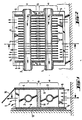
- the examples of a multivalent radiator shown in the drawing are used for room air heating with convectors acted on from different energy sources, a lower convector 1 and an upper convector 2.
- the convectors 1 are arranged in a common air duct. They are operated by heating media M 1 and M 2 from different heating sources, the upper convector 2 from a conventional heating source, the lower convector 1 from an auxiliary heating source, in particular for the use of solar energy.
- the tubular convectors 1 and 2 are covered with rectangular slats 3 and 4. Between the convector zone a of the lower temperature and the convector zone c of the higher temperature there is a transition zone b in which the lamellae 3 and 4 forming vertical trains 14 are separated from each other, either by a separation gap 8 or by insulating bridges 11 poorly heat-conducting material, for example plastic (see FIGS. 6 and 7).
- the shaft 5 is formed by a metallic one running from top to bottom Shaft wall 5 limited.
- a heat insulation zone is switched on in the heat conduction path from the convector zone c to the convector zone a in order to prevent thermal feedback via heat conduction paths.
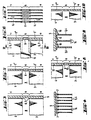
- the outer metallic shaft wall 5 is lined overall by an inner insulating wall 6 made of plastic or other, poorly heat-conducting material to form the thermal insulation zone. 3, this lining can be interrupted in the transition zone b.
- FIG. 4 the lining is replaced by insulation strips 7 with which the slats 3, 4 are connected to the metal shaft wall 5.
- the lining can also, as FIG. 9 shows, be designed as an insulation collar, which adjoin one another from lamella 3 to lamella 4 and likewise form a continuous lining.
- FIGS. 6 and 7 show lamellae 3, 4 with a solid body connection by means of insulating bridges 11.
- This embodiment is distinguished in particular by that continuous, that is, uninterrupted trains 14 are formed via the convector systems, which ensure an undisturbed ascending laminar air flow which is only subjected to the thermals. This prevents feedback from both heat conduction and air flow due to eddy formation.
- FIG. 5 shows an embodiment in which the slats 4 of the upper convector 2 are connected directly to the metal shaft wall 5.
- the feedback by heat conduction to the lower convector 1 is avoided by switching on an insulation barrier 9 between the metallic wall above and below. If heat radiation is to take place in the area of the upper convector 2, the slats 4 of this convector 2 can be connected in a heat-conducting manner to the upper shaft wall 5 ′′, while the slats 3 of the lower convector 1 against the lower metal shaft wall 5 ′ through an insulating wall or through Insulation strips 7 are thermally insulated, which means that the thermal energy of the lower convector 1 is largely used to support the upper convector 2.
- a flap 15 can be provided on the upper exit side of the shaft, through which a baffle surface for deflecting the warm air, This flap 15 can also be arranged so that it can be deflected so that, if necessary, the warm air flow is deflected away from the window front into the room.
Abstract
Description
Die Erfindung bezieht sich auf einen Heizkörper zur Raumluftbeheizung mit durch Heizmedien aus unterschiedlichen Energiequellen und verschieden hoher Temperaturstufen beaufschlagten Konvektoren, welche wärmeleitende Lamellen tragen, die entsprechend ihrer Temperaturstufe mit wärmedämmendem Abstand untereinanderliegend, einen Luftschacht in Strömungsrichtung in viele aufsteigende, unten und oben offene Züge unterteilen. Solche multivalenten Heizkörper werden beispielsweise eingesetzt, um einen Konvektor herkömmlicher Art durch Vorschaltung eines z. B. mit Sonnenenergie oder aus Rauchgasabwärme betriebenen Konvektors zu unterstützen.The invention relates to a radiator for room air heating with convectors acted upon by heating media from different energy sources and at different temperature levels, which carry heat-conducting fins, which, according to their temperature level with thermal insulation distance between them, divide an air duct in the direction of flow into many rising, open at the top and bottom . Such multivalent radiators are used, for example, to a conventional convector by connecting a z. B. to support with solar energy or flue gas operated convector.
Das bekannte multivalente Heizsystem nach der DE-A-2 945 071 hat den Nachteil, daß der Gesamtwirkungsgrad durch thermische Rückkoppelung, sei es durch Turbulenzen der Luftströmung oder durch Värmeleitung vom Konvektorsystem höherer zum Konvektorsystem niederer Temperatur beeinträchtigt wird und wirkungsgradmäßig unterhalb 50 % verbleibt. Der Erfindung liegt deshalb die Aufgabe zugrunde, im multivalenten Heizkörpersystem der nach der DE-A-2 945 071 bezeichneten Art die thermische Rückkoppelung vom Konvektorsystem höherer zum Konvektorsystem niederer Temperatur zu unterdrücken.The known multivalent heating system according to DE-A-2 945 071 has the disadvantage that the overall efficiency is impaired by thermal feedback, be it by turbulence in the air flow or by conduction of heat from the convector system to the convector system at a lower temperature and the efficiency remains below 50%. The invention is therefore based on the object of suppressing the thermal feedback from the convector system to the convector system of low temperature in the multivalent radiator system of the type described in DE-A-2 945 071.
Diese Aufgabe wird erfindungsgemäß dadurch gelöst, daß die Lamellen des Konvektors höherer Temperatur mit den Lamellen des Konvektors niederer Temperatur unter Freihaltung der offenen Züge durch Wärmedämmbrücken aus einem schlecht leitenden Material miteinander verbunden sind. Dadurch ergibt sich ein multivalentes Heizsystem mit ungestörter laminarer Strömung der Luft und praktisch rückwirkungsfreiem Wärmeaustausch in mehreren, räumlich und thermisch übereinanderliegenden Stufen. Hierbei entsteht zwischen dem oberen Konvektor mit höherer Arbeitstemperatur und dem unteren Konvektor mit niederer Arbeitstemperatur eine sogartige Arbeitsweisen.This object is achieved in that the slats of the convector of higher temperature with the slats of the convector of low temperature are connected with each other by keeping the open cables by thermal bridges made of a poorly conductive material. This results in a multivalent heating system with undisturbed laminar air flow and practically non-reactive heat exchange in several, spatially and thermally superimposed stages. This creates a so-called mode of operation between the upper convector with a higher working temperature and the lower convector with a lower working temperature.
Nach der aus der DE-A-2 945 071 bekannten Entwicklung sind die Lamellen zwar mit wärmedämmendem Abstand von einander angeordnet. Es besteht jedoch der Nachteil, daß eine thermische Rückkoppelung zwischen den beiden Konvektoren über die Schachtwandung hinweg gegeben ist. Darum geht es bei der Erfindung hier in erster Linie darum, die Rückkoppelung über die Schachtwandung auszuschließen.Die Anordnung von Wärmedämmzonen aus wärmedämmendem Feststoff ist im Bereich der benachbarten Lamellenkanten besonders wichtig zur Vermeidung von Luftwirbeln in diesem Bereich. Noch viel wichtiger ist es jedoch, die Wärmeleitung vom Konvektor höherer zum Konvektor niederer Temperatur auszuschließen, welche bei dem bekannten Heizkörper nach der DE-A-2 945 071 über die Schachtwandung vorliegt. Diese Wärmeleitung wird bei der Erfindung im Gegensatz zu der bekannten Technik dadurch unterdrückt, daß die Wärmerückkoppelung auch über den Weg mittelbarer Wärmeleitung über die Schachtwandung durch Wärmedämmzonen unterdrückt werden.According to the development known from DE-A-2 945 071, the fins are arranged at a heat-insulating distance from one another. However, there is the disadvantage that there is thermal feedback between the two convectors across the shaft wall. This is why the invention is primarily concerned with excluding feedback via the shaft wall. The arrangement of heat-insulating zones made of heat-insulating solid material is particularly important in the area of the adjacent lamella edges in order to avoid air vortices in this area. However, it is even more important to exclude the heat conduction from the convector to the convector of lower temperature, which is present in the known radiator according to DE-A-2 945 071 via the shaft wall. In contrast to the known technology, this heat conduction is suppressed in the invention in that the heat feedback is also suppressed via the path of indirect heat conduction via the shaft wall through thermal insulation zones.
In der Zeichnung ist die Erfindung an einigen Ausführungsbeispielen veranschaulicht. Es zeigt
- Fig. 1 in einem Vertikalschnitt nach nach der Linie I/I der Fig. 2 einen zweistufigen multivalenten Heizkörper,
- Fig. 2 einen Vertikalschnitt nach der
Linie 11/11 der Fig. 1 und 2, - Fig. 3 eine andere Ausführungsform der Übergangszone b der Fig. 1 und 2,
- Fig. 4 eine Ausführungsform mit Dämmleisten zum Anschluß der Konvektorlamellen an die Schachtwandung,
- Fig. 5 eine andere Gestaltung der Übergangszone,
- Fig. 6 eine Ausführungsform mit Dämmbrücken zwischen den Lamellen benachbarter Konvektoren,
- Fig. 7 einen Schnitt nach der Linie VII/VII der Fig. 6,
- Fig. 8 eine Ausführungsform mit Luftspalt zwischen den Lamellen benachbarter Konvektoren und zwischen den Lamellen und der Schachtwandung,
- Fig. 9 eine Ausführung mit kragenförmigen Dämmleisten,
- Fig. 10 eine Ausführung mit oberer Schachtwandung aus Dämmstoff.
- 1 is a vertical section along the line I / I of FIG. 2, a two-stage multivalent radiator,
- 2 shows a vertical section along the
line 11/11 of FIGS. 1 and 2, - 3 shows another embodiment of the transition zone b of FIGS. 1 and 2,
- 4 shows an embodiment with insulating strips for connecting the convector slats to the shaft wall,
- 5 shows another design of the transition zone,
- 6 shows an embodiment with insulating bridges between the lamellae of adjacent convectors,
- 7 shows a section along the line VII / VII of FIG. 6,
- 8 shows an embodiment with an air gap between the lamellae of adjacent convectors and between the lamellae and the shaft wall,
- 9 shows an embodiment with collar-shaped insulating strips,
- Fig. 10 shows an embodiment with an upper shaft wall made of insulating material.
Die in der Zeichnung dargestellten Beispiele eines multivalenten Heizkörpers dienen zur Raumluftbeheizung mit aus verschiedenen Energiequellen beaufschlagten Konvektoren, einem unteren Konvektor 1 und einem oberen Konvektor 2. Die Konvektoren 1, sind in einem gemeinsamen Luftschacht angeordnet. Sie werden durch Heizmedien M1 und M2 aus verschiedenen Heizquellen betrieben, der obere Konvektor 2 aus einer herkömmlichen Heizquelle, der untere Konvektor 1 aus einer Hilfsheizquelle, insbesondere zur Nutzung von Sonnenenergie.The examples of a multivalent radiator shown in the drawing are used for room air heating with convectors acted on from different energy sources, a
Die rohrförmigen Konvektoren 1 und 2 sind mit rechteckigen Lamellen 3 und 4 besetzt. Zwischen der Konvektorzone a der niederen Temperatur und der Konvektorzone c der höheren Temperatur befindet sich eine Übergangszone b, in welcher die miteinander fluchtenden, vertikalen Züge 14 bildenden Lamellen 3 und 4 voneinander getrennt sind, und zwar entweder durch einen Trennspalt 8 oder durch Dämmbrücken 11 aus schlecht wärmeleitendem Material, beispielsweise Kunststoff (vgl. Fig. 6 und 7). In den Ausführungsformen nach Fig. 1, 2 und 3 wird der Schacht 5 durch eine von oben bis unten durchlaufende metallische Schachtwandung 5 begrenzt. In allen Ausführungsformen ist in den Wärmeleitweg von der Konvektorzone c zur Konvektorzone a eine Wärmedämmzone eingeschaltet, um eine thermische Rückkoppelung über Wärmeleitwege zu unterbinden. In der Ausführungsform nach Fig. 1 und 2 ist zur Bildung der Wärmedämmzone die äußere metallene Schachtwandung 5 insgesamt durch eine innere Dämmwandung 6 aus Kunststoff oder sonstigem, schlecht wärmeleitendem Material ausgekleidet. Diese Auskleidung kann, wie Fig. 3 zeigt, in der Übergangszone b unterbrochen sein.The
In Fig. 4 ist die Auskleidung durch Dämmleisten 7 ersetzt, mit denen die Lamellen 3,4 an die metallene Schachtwandung 5 angeschlossen sind. Die Auskleidung kann auch, wie Fig. 9 zeigt, als Dämmkragen ausgebildet sein, welche sich von Lamelle 3 zu Lamelle 4 dicht aneinander anschließen und ebenfalls eine durchgehende Auskleidung bilden. Während in Fig. 5 und 10 die Lamellen 3,4 der Konvektoren 1, 2 durch einen einfachen Trennspalt 8 voneinander getrennt sind, zeigen Fig. 6 und 7 Lamellen 3,4 mit Festkörperverbindung durch Dämmbrücken 11. Diese Ausführungsform zeichnet sich insbesondere dadurch aus, daß über die Konvektorsysteme durchgehende, das heißt ununterbrochene Züge 14 gebildet werden, welche eine ungestörte aufsteigende laminare Luftströmung gewährleistenwelche nur der Thermik unterworfen ist. Damit werden Rückkoppelungen sowohl durch Wärmeleitung als auch durch Luftströmung infolge von Wirbelbildungen ausgeschlossen.In Fig. 4, the lining is replaced by
In der Ausführungsform nach Fig. 3 ergibt sich in der Übergangszone b eine Wärmeübertragung aus der Heizenergie des unteren Konvektorsystems auf die metallene Schachtwandung 5.In the embodiment according to FIG. 3, heat transfer from the heating energy of the lower convector system to the
Fig. 5 zeigt eine Ausführungsform, in welcher die Lamellen 4 des oberen Konvektors 2 unmittelbar mit der metallenen Schachtwandung 5 verbunden sind. Die Rückkoppelung durch Wärmeleitung zum unteren Konvektor 1 wird durch Einschaltung einer Dämmschranke 9 zwischen der metallischen Wandung oben und unten vermieden. Soll dabei eine Wärmeabstrahlung im Bereich des oberen Konvektors 2 erfolgen, so können die Lamellen 4 dieses Konvektors 2 wärmeleitend an die obere Schachtwandung 5" angeschlossen werden, während die Lamellen 3 des unteren Konvektors 1 gegen die untere metallene Schachtwandung 5' durch eine Dämmwandung oder durch Dämmleisten 7 thermisch isoliert sind. Dadurch wird erreicht, daß die Wärmeenergie des unteren Konvektors 1 weitgehend zur Unterstützung des oberen Konvektors 2 herangezogen wird. An der oberen Austrittsseite des Schachtes kann eine Klappe 15 vorgesehen sein, durch welche eine Prallfläche zur Ablenkung der warmen Luft, beispielsweise zur Fensterfront hin, erfolgt. Diese Klappe 15 kann auch umsetzbar angeordnet sein, so daß im Bedarfsfalle eine Umlenkung des Warmluftstromes von der Fensterfront weg in den Raum erreicht wird.FIG. 5 shows an embodiment in which the slats 4 of the upper convector 2 are connected directly to the
- 1, 2 Konvektoren1, 2 convectors
- 1 unterer Konvektor1 lower convector
- 2 oberer Konvektor2 upper convector
- 3 Lamellen von 13 slats of 1
- 4 Lamellen von 24 slats of 2
- 5 Schachtwandung5 shaft wall
- 5' und 5" untere u. obere Schachtwandung5 'and 5 "lower and upper shaft wall
- 6 Dämmwandung6 insulation wall
- 7 Dämmleisten7 insulation strips
- 8 Trennspalt8 separation gap
- 9 Dämmschranke9 insulation barrier
- 10 Dämmkragen10 insulation collar
- 11 Dämmzonen11 insulation zones
- 12 Dämmplatte12 insulation board
- 13 Luftspalt13 air gap
- 14 Luftspalt14 air gap
- 15 Klappe15 flap
- a untere Konvektorzonea lower convector zone
- b Übergangszoneb transition zone
- c obere Konvektorzonec upper convector zone
- s Luftschachts air shaft
Claims (2)
Priority Applications (1)
| Application Number | Priority Date | Filing Date | Title |
|---|---|---|---|
| AT84116177T ATE41226T1 (en) | 1983-12-29 | 1984-12-22 | MULTIVALENT RADIATOR FOR ROOM HEATING. |
Applications Claiming Priority (2)
| Application Number | Priority Date | Filing Date | Title |
|---|---|---|---|
| DE3347438 | 1983-12-29 | ||
| DE3347438A DE3347438A1 (en) | 1983-12-29 | 1983-12-29 | MULTIVALENT RADIATOR FOR INDOOR AIR HEATING |
Publications (3)
| Publication Number | Publication Date |
|---|---|
| EP0148495A2 EP0148495A2 (en) | 1985-07-17 |
| EP0148495A3 EP0148495A3 (en) | 1986-07-23 |
| EP0148495B1 true EP0148495B1 (en) | 1989-03-08 |
Family
ID=6218374
Family Applications (1)
| Application Number | Title | Priority Date | Filing Date |
|---|---|---|---|
| EP84116177A Expired EP0148495B1 (en) | 1983-12-29 | 1984-12-22 | Multivalent radiator for space heating |
Country Status (4)
| Country | Link |
|---|---|
| EP (1) | EP0148495B1 (en) |
| JP (1) | JPH0689934B2 (en) |
| AT (1) | ATE41226T1 (en) |
| DE (2) | DE3347438A1 (en) |
Families Citing this family (5)
| Publication number | Priority date | Publication date | Assignee | Title |
|---|---|---|---|---|
| CN101245971B (en) * | 2007-04-10 | 2010-12-08 | 马永锡 | Enclosed cavity type heat exchanger |
| JP5006122B2 (en) | 2007-06-29 | 2012-08-22 | 株式会社Sokudo | Substrate processing equipment |
| JP5128918B2 (en) | 2007-11-30 | 2013-01-23 | 株式会社Sokudo | Substrate processing equipment |
| JP5001828B2 (en) | 2007-12-28 | 2012-08-15 | 株式会社Sokudo | Substrate processing equipment |
| JP5179170B2 (en) | 2007-12-28 | 2013-04-10 | 株式会社Sokudo | Substrate processing equipment |
Family Cites Families (6)
| Publication number | Priority date | Publication date | Assignee | Title |
|---|---|---|---|---|
| DE840252C (en) * | 1942-06-06 | 1952-05-29 | Basf Ag | Gas-heated cross-flow heat exchanger |
| FR1217649A (en) * | 1958-05-17 | 1960-05-04 | Central heating radiator with hot water or low pressure steam | |
| FR1389311A (en) * | 1964-04-13 | 1965-02-12 | Finned tube system, in particular for steam boiler feedwater preheaters | |
| DE2747344A1 (en) * | 1977-10-21 | 1979-04-26 | Gerhard Dipl Ing Pruefling | Heating radiator with rectangular steel water tubes - has adhesive bonded aluminium ribs providing high heat transfer rate |
| DE7928453U1 (en) * | 1979-10-06 | 1980-02-28 | Skapargiotis, Georg, 7850 Loerrach | RADIATOR, IN PARTICULAR FOR A CENTRAL HEATING SYSTEM |
| DE2945071A1 (en) * | 1979-11-08 | 1981-05-21 | Ulrich 2814 Bruchhausen-Vilsen Grigat | Heat exchanger which operates upward air flow - directed across horizontal pipes of conventional and solar heating systems |
-
1983
- 1983-12-29 DE DE3347438A patent/DE3347438A1/en active Granted
-
1984
- 1984-12-22 DE DE8484116177T patent/DE3477049D1/en not_active Expired
- 1984-12-22 AT AT84116177T patent/ATE41226T1/en not_active IP Right Cessation
- 1984-12-22 EP EP84116177A patent/EP0148495B1/en not_active Expired
- 1984-12-27 JP JP59274242A patent/JPH0689934B2/en not_active Expired - Fee Related
Also Published As
| Publication number | Publication date |
|---|---|
| EP0148495A2 (en) | 1985-07-17 |
| DE3347438C2 (en) | 1987-06-04 |
| DE3477049D1 (en) | 1989-04-13 |
| JPH0689934B2 (en) | 1994-11-14 |
| DE3347438A1 (en) | 1985-07-18 |
| ATE41226T1 (en) | 1989-03-15 |
| JPS60228896A (en) | 1985-11-14 |
| EP0148495A3 (en) | 1986-07-23 |
Similar Documents
| Publication | Publication Date | Title |
|---|---|---|
| DE2725239A1 (en) | HEAT EXCHANGE SYSTEM AND METAL PANEL FOR A HEAT EXCHANGE SYSTEM | |
| EP0186756A1 (en) | Fluidized-bed combustion with immersion heating surfaces | |
| EP0148495B1 (en) | Multivalent radiator for space heating | |
| EP0449124B1 (en) | Annular space heat exchanger | |
| DE2126226C3 (en) | Heat exchanger | |
| EP1108963A2 (en) | Combustion gas heat exchanger | |
| EP0045491B1 (en) | Space heater for small rooms | |
| EP0473946B1 (en) | Sectional boiler | |
| DE202015103710U1 (en) | Gas-fluid counterflow heat exchanger | |
| EP0254760A1 (en) | Room heating device for small rooms | |
| DE2239086C2 (en) | Heat exchanger for water flow heater - has distance ribs between pipes, with recess to impede heat transfer | |
| DE1613759C3 (en) | Cooling device for transformers | |
| DE3232794A1 (en) | Combustion chamber floor for a fluidised bed furnace | |
| DE1933688A1 (en) | Lamellar radiators | |
| DE273686C (en) | ||
| EP1072846A2 (en) | Ceiling mounted convector | |
| DE3327094A1 (en) | Arrangement for recovering the thermal energy contained in combustion waste gases, in particular furnace waste gases | |
| DE3313296A1 (en) | Heating surface structure | |
| DE3431343A1 (en) | Immersion-heating surfaces for fluidised-bed firing | |
| DE2217065C3 (en) | Stove top | |
| DE2807612A1 (en) | HEAT EXCHANGER | |
| DE3105230A1 (en) | Space-heating furnace | |
| DE3010773A1 (en) | Heat exchanger esp. for heat recovery in chimney - has two or more exchanger units of cold side arranged along hot flue duct | |
| DE3624394A1 (en) | Heater (radiator) | |
| DE8128210U1 (en) | DEVICE FOR INCREASING THE HEAT EXPLOITATION IN A ROOM FIREPLACE OR FIRE FIRE |
Legal Events
| Date | Code | Title | Description |
|---|---|---|---|
| PUAI | Public reference made under article 153(3) epc to a published international application that has entered the european phase |
Free format text: ORIGINAL CODE: 0009012 |
|
| AK | Designated contracting states |
Designated state(s): AT BE CH DE FR GB IT LI LU NL SE |
|
| PUAL | Search report despatched |
Free format text: ORIGINAL CODE: 0009013 |
|
| AK | Designated contracting states |
Kind code of ref document: A3 Designated state(s): AT BE CH DE FR GB IT LI LU NL SE |
|
| 17P | Request for examination filed |
Effective date: 19860805 |
|
| 17Q | First examination report despatched |
Effective date: 19861107 |
|
| GRAA | (expected) grant |
Free format text: ORIGINAL CODE: 0009210 |
|
| AK | Designated contracting states |
Kind code of ref document: B1 Designated state(s): AT BE CH DE FR GB IT LI LU NL SE |
|
| PG25 | Lapsed in a contracting state [announced via postgrant information from national office to epo] |
Ref country code: NL Effective date: 19890308 Ref country code: IT Free format text: LAPSE BECAUSE OF FAILURE TO SUBMIT A TRANSLATION OF THE DESCRIPTION OR TO PAY THE FEE WITHIN THE PRESCRIBED TIME-LIMIT;WARNING: LAPSES OF ITALIAN PATENTS WITH EFFECTIVE DATE BEFORE 2007 MAY HAVE OCCURRED AT ANY TIME BEFORE 2007. THE CORRECT EFFECTIVE DATE MAY BE DIFFERENT FROM THE ONE RECORDED. Effective date: 19890308 |
|
| REF | Corresponds to: |
Ref document number: 41226 Country of ref document: AT Date of ref document: 19890315 Kind code of ref document: T |
|
| REF | Corresponds to: |
Ref document number: 3477049 Country of ref document: DE Date of ref document: 19890413 |
|
| ET | Fr: translation filed | ||
| NLV1 | Nl: lapsed or annulled due to failure to fulfill the requirements of art. 29p and 29m of the patents act | ||
| GBT | Gb: translation of ep patent filed (gb section 77(6)(a)/1977) | ||
| PG25 | Lapsed in a contracting state [announced via postgrant information from national office to epo] |
Ref country code: AT Effective date: 19891222 |
|
| PG25 | Lapsed in a contracting state [announced via postgrant information from national office to epo] |
Ref country code: LU Free format text: LAPSE BECAUSE OF NON-PAYMENT OF DUE FEES Effective date: 19891231 |
|
| PLBE | No opposition filed within time limit |
Free format text: ORIGINAL CODE: 0009261 |
|
| STAA | Information on the status of an ep patent application or granted ep patent |
Free format text: STATUS: NO OPPOSITION FILED WITHIN TIME LIMIT |
|
| PGFP | Annual fee paid to national office [announced via postgrant information from national office to epo] |
Ref country code: GB Payment date: 19900131 Year of fee payment: 6 |
|
| 26N | No opposition filed | ||
| PG25 | Lapsed in a contracting state [announced via postgrant information from national office to epo] |
Ref country code: GB Effective date: 19901222 |
|
| GBPC | Gb: european patent ceased through non-payment of renewal fee | ||
| PGFP | Annual fee paid to national office [announced via postgrant information from national office to epo] |
Ref country code: CH Payment date: 19940622 Year of fee payment: 10 |
|
| PGFP | Annual fee paid to national office [announced via postgrant information from national office to epo] |
Ref country code: SE Payment date: 19940623 Year of fee payment: 10 |
|
| PGFP | Annual fee paid to national office [announced via postgrant information from national office to epo] |
Ref country code: BE Payment date: 19940628 Year of fee payment: 10 |
|
| PG25 | Lapsed in a contracting state [announced via postgrant information from national office to epo] |
Ref country code: SE Effective date: 19941223 |
|
| PG25 | Lapsed in a contracting state [announced via postgrant information from national office to epo] |
Ref country code: LI Effective date: 19941231 Ref country code: CH Effective date: 19941231 Ref country code: BE Effective date: 19941231 |
|
| EAL | Se: european patent in force in sweden |
Ref document number: 84116177.1 |
|
| BERE | Be: lapsed |
Owner name: GRIGAT ULRICH Effective date: 19941231 |
|
| REG | Reference to a national code |
Ref country code: CH Ref legal event code: PL |
|
| EUG | Se: european patent has lapsed |
Ref document number: 84116177.1 |
|
| REG | Reference to a national code |
Ref country code: FR Ref legal event code: ST |
|
| REG | Reference to a national code |
Ref country code: FR Ref legal event code: RN |
|
| PGFP | Annual fee paid to national office [announced via postgrant information from national office to epo] |
Ref country code: FR Payment date: 19970630 Year of fee payment: 13 |
|
| REG | Reference to a national code |
Ref country code: FR Ref legal event code: FC |
|
| PGFP | Annual fee paid to national office [announced via postgrant information from national office to epo] |
Ref country code: DE Payment date: 19971031 Year of fee payment: 13 |
|
| PG25 | Lapsed in a contracting state [announced via postgrant information from national office to epo] |
Ref country code: FR Free format text: THE PATENT HAS BEEN ANNULLED BY A DECISION OF A NATIONAL AUTHORITY Effective date: 19971231 |
|
| PG25 | Lapsed in a contracting state [announced via postgrant information from national office to epo] |
Ref country code: DE Free format text: LAPSE BECAUSE OF NON-PAYMENT OF DUE FEES Effective date: 19980901 |
|
| REG | Reference to a national code |
Ref country code: FR Ref legal event code: ST |