EP0148402B1 - Dispositif d'entrelacement d'un fil multifilaments - Google Patents
Dispositif d'entrelacement d'un fil multifilaments Download PDFInfo
- Publication number
- EP0148402B1 EP0148402B1 EP84114636A EP84114636A EP0148402B1 EP 0148402 B1 EP0148402 B1 EP 0148402B1 EP 84114636 A EP84114636 A EP 84114636A EP 84114636 A EP84114636 A EP 84114636A EP 0148402 B1 EP0148402 B1 EP 0148402B1
- Authority
- EP
- European Patent Office
- Prior art keywords
- nozzle
- interlacing
- passage
- blowing
- axis
- Prior art date
- Legal status (The legal status is an assumption and is not a legal conclusion. Google has not performed a legal analysis and makes no representation as to the accuracy of the status listed.)
- Expired
Links
Images


Classifications
-
- D—TEXTILES; PAPER
- D01—NATURAL OR MAN-MADE THREADS OR FIBRES; SPINNING
- D01H—SPINNING OR TWISTING
- D01H1/00—Spinning or twisting machines in which the product is wound-up continuously
- D01H1/11—Spinning by false-twisting
- D01H1/115—Spinning by false-twisting using pneumatic means
-
- D—TEXTILES; PAPER
- D02—YARNS; MECHANICAL FINISHING OF YARNS OR ROPES; WARPING OR BEAMING
- D02J—FINISHING OR DRESSING OF FILAMENTS, YARNS, THREADS, CORDS, ROPES OR THE LIKE
- D02J1/00—Modifying the structure or properties resulting from a particular structure; Modifying, retaining, or restoring the physical form or cross-sectional shape, e.g. by use of dies or squeeze rollers
- D02J1/08—Interlacing constituent filaments without breakage thereof, e.g. by use of turbulent air streams
Definitions
- the invention relates to a device for interlacing a multifilament yarn, as described in the preamble of the first claim.
- multifilament yarns are interlaced in order to interweave the individual filament fibrils. This interlacing takes place selectively or continuously and has the advantage of better holding the filament yarn together for the subsequent stages of the operation.
- the interlacing of multifilament yarns requires an adaptation of the interlacing nozzles to different operating conditions such as B. Feed speed of the yarn, type of yarn, i.e. Differentiation between crimped and smooth yarns as well as cross-section resp. Shape of the individual filament fibrils. Accordingly, the number and positions of the injection nozzles generally have to be optimized by trials. The values recorded in these tests must be reproducible with high precision in order to avoid the incorrect productions which sometimes only result from very small deviations of these values.
- a blow nozzle is provided therein in a rotatable insert part provided for turning with a screw slot, the axis of rotation of which lies in an imaginary plane, which likewise contains the cross section of the swirl channel.
- the blowing nozzle is provided in relation to the axis of rotation of the insert part in such a way that the center line of the blowing nozzle also lies in the aforementioned imaginary plane.
- the device mentioned in the preamble of the first claim is according to the invention by the measure defined in the characterizing part of the first claim improved.
- a device 1 for intermingling a multifilament 2 (FIG. 2) in an interlacing channel 3 comprises a main part 4 and a secondary part 5 attached thereto. Both parts comprise the interlacing channel 3 and are held together by pressing elements (not shown).
- a slide 6 is arranged transversely to the swirling channel 3 in such a way that a blowing nozzle 7 provided transversely through this slide 6 opens into the swirling channel 3.
- the slide 6 rests against a compression spring 8 supported in the main part 4 and with the other end face against a pressure pin 9.
- the pressure pin 9 is part of a screw 10 guided in the main part 4.
- the slide is manufactured in such a way that, despite the displaceable arrangement of the slide 6, as little leakage air as possible on the cylindrical periphery of the slide 6 can get into the swirl channel 3 from a compressed air space 11.
- the compressed air space 11 is provided on the side of the slide 6 opposite the swirl channel 3 and is fed with compressed air by means of a compressed air connection 12.
- the compressed air comes from the compressed air space 11 through the blowing nozzle into the swirl channel 3.
- the slide 6 can be fixed in a selected position by means of a positioning screw 13.
- the positioning screw 13 engages in a groove 14 provided on the slide 6.
- the blowing nozzle 7 is shifted within one working area A by moving the slide 6 in one direction or the other R until a desired swirling of the multifilament 2 takes place.
- the working area of the blowing nozzles is to be understood as the area within which the position of the blowing nozzles can be changed without them even partially not opening into the swirl channel.
- the groove 14 is provided such that the blowing nozzle 7 is essentially perpendicular to the swirl channel 3.
- the groove 14 it is also possible to arrange the groove 14 in such a way that the blowing nozzle 7 is at an angle to the swirl channel 3, i.e. for example in such a way that the air flowing out of the blowing nozzle into the swirl channel helps to move the filament in the feed direction (not shown) of the filament 2.
- blowing nozzles 15 and 15 are respectively arranged for the blowing nozzle 7. 16 provided, the axes of symmetry 17 respectively. 18 essentially intersect on the axis of symmetry S (FIG. 3) of the swirl channel 3.
- a secondary part 105 serves to receive the blowing nozzle 15 and 16 and the compressed air connections 12 required for this.
- the axes of symmetry 17 and 18 of the blowing nozzles 15 and 16 enclose an angle of essentially 120 °.
- the axes of symmetry 19 of the blowing nozzle 7 passes through the intersection of the axes of symmetry 17 and 18, the axes of symmetry 17 and 19 and 18 and 19 each essentially enclose an angle of likewise 120 °.
- the secondary part 5 as well as the secondary part 105 are joined together in a parting plane 20 essentially impermeable to air.
- 105 is not the subject of the invention.
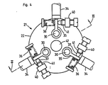
- FIGS. 4 to 6 A further device 21 according to the invention is shown in FIGS. 4 to 6, in which an upper part 22, a middle part 23 and a lower part 24 are firmly joined together by means of connecting elements (not shown) in a so-called sandwich construction.
- the parts 22, 23 and 24 are joined together in parting planes 25 and 26.
- the middle part 23 has three recesses 27, each for receiving a nozzle part 28.
- the nozzle part 28 consists of a disk-shaped nozzle carrier 29 with a shaft 30 and a compressed air supply pipe 31 with a compressed air supply bore 33.
- a blowing nozzle 32 provided in the nozzle part 28 forms the continuation of a compressed air supply bore 33 of the supply pipe 31.
- the nozzle carrier 29 is connected to a compressed air supply element (not shown) by means of a flexible connecting tube 34.
- An adjusting lever 35 is fixedly connected to the free end of the shaft 30 and is moved on the one hand by a compression spring 36 (FIG. 4) and a pressure pin 37 opposite this spring.
- the compression spring is attached at one end to the lever 35 and at the other end to a support plate 38.
- the support plate in turn is firmly connected to the surface 39 (FIG. 5) of the upper part 22.
- a carrier 40 provided with a threaded bore serves to receive the pressure bolt 37 provided with a corresponding thread 41.
- the carrier 40 is likewise firmly connected to the surface 39.
- the device 21 has a swirl channel 42, into which each nozzle holder projects to such an extent that the mouth of the blowing nozzle 32 can be adjusted within the working area A already described.
- the blow nozzle 32 can for example be arranged obliquely to the swirl channel 42 in such a way that the air flowing out of the blow nozzle 32 conveys the conveyance of the filament 2 supported in its feed direction.
- the advantage of the device of FIGS. 4-7 lies in the possibility of being able to adjust one, all or only two of the blowing nozzles in the working area A.
- Another advantage of this triple adjustability of the blowing nozzles is the possibility to use the device for texturing the yarn.
- a two-dimensional adjustability of the blow nozzles is provided with the device 50 in FIGS. 8 and 9.
- the device 50 comprises a block body 51 with three spherical bores 52 provided therein in the same plane, each for receiving a spherical nozzle body 53 corresponding to this bore 52.
- a threaded bore concentric with each spherical bore 52 serves to receive a fixing part 54 provided with a corresponding external thread 59 and with a cylindrical cavity 60.
- a spherical nozzle body 53 adapted spherical surface 56 is provided at the end of the cylindrical cavity 60 directed against a swirl channel 55 provided centrally in the block body 51 .
- the spherical nozzle body 53 further comprises a compressed air supply pipe 57 with a compressed air supply bore 61, which opens into the swirling channel 55 as a blowing nozzle 58.
- a connecting pipe 59 connected to the compressed air supply pipe is connected to a compressed air supply element (not shown).
- the advantage of this variant is that it is possible during operation to either fix all three blow nozzles in such a way that their axes of symmetry (not shown) intersect at one point or in any deviations from it in a spherical cutout due to the spherical mobility of the blow nozzles Can move work area (not shown), which is given by the fact that the axes of symmetry (not shown) when moving the blowing nozzle at the boundaries of the work area describes the lateral surface of a cone, the axis of rotation of which is substantially perpendicular to the axis of symmetry of the swirl channel 55.
- the device 21 or. 50 for the more advantageous introduction of the multi-filament 2 into the swirling channel 42, respectively. 55 can be divided, this can be provided in an analogous manner, as shown and described with FIGS. 1 and 3.
Landscapes
- Engineering & Computer Science (AREA)
- Textile Engineering (AREA)
- Physics & Mathematics (AREA)
- Fluid Mechanics (AREA)
- Mechanical Engineering (AREA)
- Yarns And Mechanical Finishing Of Yarns Or Ropes (AREA)
Claims (8)
Applications Claiming Priority (2)
| Application Number | Priority Date | Filing Date | Title |
|---|---|---|---|
| CH677283 | 1983-12-20 | ||
| CH6772/83 | 1983-12-21 |
Publications (2)
| Publication Number | Publication Date |
|---|---|
| EP0148402A1 EP0148402A1 (fr) | 1985-07-17 |
| EP0148402B1 true EP0148402B1 (fr) | 1987-08-12 |
Family
ID=4314781
Family Applications (1)
| Application Number | Title | Priority Date | Filing Date |
|---|---|---|---|
| EP84114636A Expired EP0148402B1 (fr) | 1983-12-20 | 1984-12-01 | Dispositif d'entrelacement d'un fil multifilaments |
Country Status (4)
| Country | Link |
|---|---|
| US (2) | US4631791A (fr) |
| EP (1) | EP0148402B1 (fr) |
| JP (1) | JPS60146038A (fr) |
| DE (1) | DE3465351D1 (fr) |
Families Citing this family (11)
| Publication number | Priority date | Publication date | Assignee | Title |
|---|---|---|---|---|
| IN171021B (fr) * | 1987-04-27 | 1992-07-04 | Rieter Ag Maschf | |
| JP2865860B2 (ja) * | 1989-09-05 | 1999-03-08 | ヘーベルライン ファーザーテヒノロギー アクチエンゲゼルシャフト | 少なくとも1本のマルチフィラメント糸をブローテクスチャード加工するための装置 |
| US5195313A (en) * | 1990-11-28 | 1993-03-23 | Basf Corporation | Method for evaluating entangled yarn |
| DE4422252A1 (de) * | 1993-07-15 | 1995-01-19 | Barmag Barmer Maschf | Texturierdüse |
| CA2194843A1 (fr) * | 1996-01-12 | 1997-07-13 | Hans-Joachim Weiss | Methode et appareil pour produire un fil multicolore a partir de fils composants de filaments de couleurs differentes |
| IT1289927B1 (it) * | 1997-02-19 | 1998-10-19 | G I B A S P A | Processo e apparato per la volumizzazione e simultanea interlacciatura di fili termoplastici con impiego di fluidi di riscaldamento |
| US5970593A (en) * | 1997-09-12 | 1999-10-26 | International Machinery Sales, Inc. | Jet for interlacing textile yarns |
| US5976453A (en) * | 1998-06-29 | 1999-11-02 | Owens-Corning Sweden Ab | Device and process for expanding strand material |
| US8474115B2 (en) * | 2009-08-28 | 2013-07-02 | Ocv Intellectual Capital, Llc | Apparatus and method for making low tangle texturized roving |
| BR112014012386B1 (pt) * | 2011-11-22 | 2021-08-17 | Ocv Intellectual Capital, Llc | Dispositivo para texturizar um material de cordão |
| KR102544309B1 (ko) | 2017-08-31 | 2023-06-16 | 오웬스 코닝 인텔렉츄얼 캐피탈 엘엘씨 | 스트랜드 재료를 텍스처링하기 위한 장치 |
Family Cites Families (4)
| Publication number | Priority date | Publication date | Assignee | Title |
|---|---|---|---|---|
| FR1523271A (fr) * | 1967-03-10 | 1968-05-03 | Rhodiaceta | Nouveau fil, procédé et dispositif pour le fabriquer |
| JPS4833424A (fr) * | 1971-09-03 | 1973-05-10 | ||
| US3823450A (en) * | 1973-04-06 | 1974-07-16 | T Biegasik | Texturing jet |
| US4245378A (en) * | 1979-09-24 | 1981-01-20 | Enterprise Machine And Development Corp. | Air jet for interlacing multifilament yarn |
-
1984
- 1984-12-01 DE DE8484114636T patent/DE3465351D1/de not_active Expired
- 1984-12-01 EP EP84114636A patent/EP0148402B1/fr not_active Expired
- 1984-12-11 US US06/680,526 patent/US4631791A/en not_active Expired - Fee Related
- 1984-12-13 JP JP59261906A patent/JPS60146038A/ja active Pending
-
1986
- 1986-09-15 US US06/907,390 patent/US4667380A/en not_active Expired - Fee Related
Also Published As
| Publication number | Publication date |
|---|---|
| US4631791A (en) | 1986-12-30 |
| US4667380A (en) | 1987-05-26 |
| EP0148402A1 (fr) | 1985-07-17 |
| JPS60146038A (ja) | 1985-08-01 |
| DE3465351D1 (en) | 1987-09-17 |
Similar Documents
| Publication | Publication Date | Title |
|---|---|---|
| EP0148402B1 (fr) | Dispositif d'entrelacement d'un fil multifilaments | |
| DD285562A5 (de) | Einstellvorrichtung, insbesondere fuer werkzeuge | |
| EP0882535B1 (fr) | Dispositif pour corriger les défauts d'alignement d'un outil | |
| DE3924688A1 (de) | Zerspanungswerkzeug | |
| EP0968783B1 (fr) | Porte-plaquette avec positionnement fin radial | |
| EP0870580A1 (fr) | Etau | |
| DE2826790C2 (de) | Spinnkopf zur Herstellung von Mehrkomponentenfäden | |
| DE3743516C2 (de) | Spleißkammer mit veränderbaren Drucklufteinmündungsöffnungen | |
| DE2943892A1 (de) | Spannvorrichtung | |
| DE10340604B3 (de) | Verfahren und Vorrichtung zum lösbaren Befestigen sowie zum Verändern der Relativposition zweier Bauteile zueinander | |
| WO1993004815A1 (fr) | Dispositif de serrage de pieces sur des machines a usiner ou a mesurer | |
| EP0178434A1 (fr) | Mandrin à mâchoires pour mandrin de perceuse | |
| DE2436501C3 (de) | Bohrstange | |
| EP0803322A1 (fr) | Dispositif pour l'ajustement précis de butées | |
| DE2121316A1 (de) | Stahlhalter für Bohrkopf | |
| DE1256514B (de) | Schneidplatte fuer ein spanabhebendes Werkzeug, insbesondere Drehwerkzeug | |
| DE4133761C2 (fr) | ||
| DE4224633C2 (de) | Fadenspleißvorrichtung für schwer spleißbare Garnarten | |
| EP0211974A1 (fr) | Elément de palier pour un patin aérostatique de palier linéaire | |
| CH679653A5 (fr) | ||
| DE4407270C1 (de) | Schneidplatten-Einstellvorrichtung | |
| EP0389788A2 (fr) | Ensemble pour pratiquer des rainures à diamètre continûment variable dans la matière pleine | |
| DE19635889A1 (de) | Werkzeugeinheit | |
| EP3697952A1 (fr) | Filière d'entrelacement ou filière de texturation et dispositif de traitement de fil | |
| DE2703332A1 (de) | Ausrichtvorrichtung fuer ein bearbeitungswerkzeug |
Legal Events
| Date | Code | Title | Description |
|---|---|---|---|
| PUAI | Public reference made under article 153(3) epc to a published international application that has entered the european phase |
Free format text: ORIGINAL CODE: 0009012 |
|
| AK | Designated contracting states |
Designated state(s): CH DE FR GB IT LI |
|
| 17P | Request for examination filed |
Effective date: 19850531 |
|
| 17Q | First examination report despatched |
Effective date: 19860430 |
|
| GRAA | (expected) grant |
Free format text: ORIGINAL CODE: 0009210 |
|
| AK | Designated contracting states |
Kind code of ref document: B1 Designated state(s): CH DE FR GB IT LI |
|
| REF | Corresponds to: |
Ref document number: 3465351 Country of ref document: DE Date of ref document: 19870917 |
|
| ITF | It: translation for a ep patent filed |
Owner name: GUZZI E RAVIZZA S.R.L. |
|
| ET | Fr: translation filed | ||
| PLBE | No opposition filed within time limit |
Free format text: ORIGINAL CODE: 0009261 |
|
| STAA | Information on the status of an ep patent application or granted ep patent |
Free format text: STATUS: NO OPPOSITION FILED WITHIN TIME LIMIT |
|
| 26N | No opposition filed | ||
| ITTA | It: last paid annual fee | ||
| PGFP | Annual fee paid to national office [announced via postgrant information from national office to epo] |
Ref country code: GB Payment date: 19931115 Year of fee payment: 10 Ref country code: DE Payment date: 19931115 Year of fee payment: 10 Ref country code: CH Payment date: 19931115 Year of fee payment: 10 |
|
| PGFP | Annual fee paid to national office [announced via postgrant information from national office to epo] |
Ref country code: FR Payment date: 19931119 Year of fee payment: 10 |
|
| PG25 | Lapsed in a contracting state [announced via postgrant information from national office to epo] |
Ref country code: GB Effective date: 19941201 |
|
| PG25 | Lapsed in a contracting state [announced via postgrant information from national office to epo] |
Ref country code: LI Effective date: 19941231 Ref country code: CH Effective date: 19941231 |
|
| GBPC | Gb: european patent ceased through non-payment of renewal fee |
Effective date: 19941201 |
|
| PG25 | Lapsed in a contracting state [announced via postgrant information from national office to epo] |
Ref country code: FR Effective date: 19950831 |
|
| REG | Reference to a national code |
Ref country code: CH Ref legal event code: PL |
|
| PG25 | Lapsed in a contracting state [announced via postgrant information from national office to epo] |
Ref country code: DE Effective date: 19950901 |
|
| REG | Reference to a national code |
Ref country code: FR Ref legal event code: ST |