EP0148276B1 - Imprimante - Google Patents
Imprimante Download PDFInfo
- Publication number
- EP0148276B1 EP0148276B1 EP19840902539 EP84902539A EP0148276B1 EP 0148276 B1 EP0148276 B1 EP 0148276B1 EP 19840902539 EP19840902539 EP 19840902539 EP 84902539 A EP84902539 A EP 84902539A EP 0148276 B1 EP0148276 B1 EP 0148276B1
- Authority
- EP
- European Patent Office
- Prior art keywords
- cover film
- printing paper
- platen
- ribbon
- photographic paper
- Prior art date
- Legal status (The legal status is an assumption and is not a legal conclusion. Google has not performed a legal analysis and makes no representation as to the accuracy of the status listed.)
- Expired
Links
Images


Classifications
-
- B—PERFORMING OPERATIONS; TRANSPORTING
- B41—PRINTING; LINING MACHINES; TYPEWRITERS; STAMPS
- B41J—TYPEWRITERS; SELECTIVE PRINTING MECHANISMS, i.e. MECHANISMS PRINTING OTHERWISE THAN FROM A FORME; CORRECTION OF TYPOGRAPHICAL ERRORS
- B41J29/00—Details of, or accessories for, typewriters or selective printing mechanisms not otherwise provided for
-
- B—PERFORMING OPERATIONS; TRANSPORTING
- B41—PRINTING; LINING MACHINES; TYPEWRITERS; STAMPS
- B41M—PRINTING, DUPLICATING, MARKING, OR COPYING PROCESSES; COLOUR PRINTING
- B41M5/00—Duplicating or marking methods; Sheet materials for use therein
- B41M5/26—Thermography ; Marking by high energetic means, e.g. laser otherwise than by burning, and characterised by the material used
- B41M5/34—Multicolour thermography
- B41M5/345—Multicolour thermography by thermal transfer of dyes or pigments
-
- B—PERFORMING OPERATIONS; TRANSPORTING
- B41—PRINTING; LINING MACHINES; TYPEWRITERS; STAMPS
- B41M—PRINTING, DUPLICATING, MARKING, OR COPYING PROCESSES; COLOUR PRINTING
- B41M7/00—After-treatment of prints, e.g. heating, irradiating, setting of the ink, protection of the printed stock
- B41M7/0054—After-treatment of prints, e.g. heating, irradiating, setting of the ink, protection of the printed stock using protective coatings or film forming compositions cured by thermal means, e.g. infrared radiation, heat
Definitions
- This invention relates to printers.
- GB-A-2 106 148 discloses a sublimation transfer type printer in which an ink ribbon containing a sublimation dye is positioned adjacent a sheet of printing paper and heated with a heating pattern corresponding to picture image information so as to transfer the sublimation dye on to the printing paper whereby the picture image is printed on the printing paper.
- Such printers can, for example, be used for printing out, as a hard copy, a still picture image of various picture images such as a picture image taken by a video camera, a television picture image and so on.
- a known sublimation transfer type printer shown in Figure 1 of the accompanying drawings comprises a platen 2, which has a sheet of printing paper 1 wound around it and which rotates in the direction shown by an arrow a, and a thermal print head 4 which contacts the platen, gripping therebetween an ink ribbon 3 for use in thermal transfer printing.
- the thermal print head 4 is provided at a tip end thereof with a plurality of heat generating elements (head elements) 4a, the number of which corresponds to a number of picture elements in one scanning line of, for example, a television (video) picture image.
- the ink ribbon 3 for use in thermal transfer printing which is closely held between the thermal print head 4 and the printing paper 1, is formed of a sheet-like carrier base material 9 on which ink portions of configuration or shape corresponding to that of a picture screen of the television picture image and containing sublimation dyes of respective colours, for example yellow, magenta, cyan and black, namely yellow ink portions Y, magenta ink portions M, cyan ink portions C and black ink portions B, are repeatedly arranged in turn.
- Ink portion position detecting marks 5Y, 5M, 5C and 5B are formed on one side edge of the ink ribbon 3 at the positions of the ink portions of corresponding colours so as to enable the positions of the ink portions to be detected, and block position detecting marks 6 are formed on the other side edge of the ink ribbon 3 so as to enable detection of each of a plurality of groups of the ink portions, each group being a block formed by the combination of adjacent ink portions Y, M, C and B of the four different colours.
- the elements 4a of the thermal print head 4 are heated in a pattern corresponding to the picture elements of one scanning line, in accordance with information corresponding to the colour yellow, for example a yellow colour signal of a television video signal, so as to thermally transfer a line of the yellow sublimation dye of the yellow ink portion Y on to the printing paper 1 in accordance with the pattern.
- the platen 2 is intermittently rotated (stepped) in the direction of the arrow a and information for that line is thermally transferred to the printing paper 1, whereby the yellow colour of a whole picture is transferred to the printing paper, line by line, during one revolution of the platen 2.
- similar transfer processes are carried out for a magenta ink portion M, a cyan ink portion C a black ink portion B, the transferred picture images of the yellow magenta, cyan and black sublimation dyes being superposed on one another so as to print a colour picture image on the printing paper 1.
- Detecting means is provided for detecting the marks 5 (5Y, 5M, 5C and 5B) and 6 in order that, for the respective ink portions Y, M, C and B, signals corresponding to the respective colour signals are supplied to the head elements 4a of the head 4.
- the detecting means may comprise, for example, a light source 7 for emitting a light ray for use in detection, for example an infra-red ray emitting diode, and a detecting element 8 for detecting the infra-red ray, the source 7 and detecting element 8 being disposed in opposing relationship to each other on opposite sides of the thermal transfer recording ink ribbon where the marks 5 and 6 are provided.
- the detecting means detects whether the marks 5 and 6 are or are not present and produces at the detecting element 8 a signal which indicates the position of the ink ribbon 3 relative to the thermal print head 4.
- a cover film which can prevent the transferring picture image from becoming faded in colour and which can obtain a heating effect for raising the colouring by minutely diffusing the dye, is hot pressed on the printing paper 1.
- the cover film is hot pressed on the printing paper 1 by a laminator that is usually provided independently of the printer.
- the laminator comprises a pair of metal heating rolls 10 and 11 as shown, for example, in Figure 2 of the accompanying drawings, and the printing paper 1 and a cover film 12, which are superposed on each other, are transported between the rolls 10 and 11 while in close contact therewith.
- the laminator of such construction has a large heat capacity so that it requires a very long time and much energy to heat and cool it, and also requires cooling means for lowering the ambient temperature, whereby the laminator is of large size. Further, there is a problem of matching position between the printing paper 1 and the cover film 12.
- the position matching between the printed printing paper 1 and the cover film 12 is difficult, and if the front surface and the back surface of the cover film 12 are mis-selected, the cover film is wound around the rolls 10 and 11, making the printing paper dirty and so on.
- the rolls 10 and 11 tend to come into surface contact with each other, a large pressure is required and bubbles are easily formed between the printing paper 1 and the cover film 12.
- a cover film 13 comprising a transparent resinous layer which can be released from the base material 9 is located behind (after) the ink portions containing the sublimation dyes formed on the base material 9 of, for example, the ink ribbon 3, namely, the yellow ink portions Y, the magenta ink portions M, the cyan ink portions C and the black ink portions B.
- the cover film layer 13 is transferred to and coated on the printing paper 1 after each sublimation dye has been transferred by the thermal print head 4.
- the respective ink portions Y, M, C, B and the cover film 13 are each printed by gravure printing.
- the cover film layer 13 since the cover film layer 13 must be coated to have a thickness much larger than those of the ink portions Y, M, C and B, the cover film layer 13 is printed after the ink portions Y, M, C and B have been printed. It is, however, difficult to form the cover film layer 13 as a layer having a sufficient thickness and a uniform and smooth surface by one printing process and, when the cover film layer is formed, the other ink portions Y, M, C and B are affected, resulting in various problems as regards the function as a cover film and from the production standpoint.
- a printer comprising:
- the cover film can be laminated on the printing paper easily and positively (that is with certainty or reliably) and, also, the overall arrangement of the apparatus can be made of small size and of simple construction.
- the ink ribbon and cover film are separate.
- the ribbon has a predetermined sublimation dye portion or portions and a cover film formed in a predetermined alignment
- the thermal print head is formed of a number of heat generating elements for heating the sublimation dye portion of the ribbon in accordance with picture image information with the sublimation dye portion of the ribbon and the printing paper on the platen in close contact with each other and for transferring sublimation dyes on to the printing paper so as to print a picture image on the printing paper.
- the thermal head for hot pressing the cover film may comprise a single heat generating portion of a width at least equal to the full width of the sublimation dye portions (ink portions).
- the ink ribbon 3 used with the printer of Figure 4 is of such a structure that the respective ink portions, for example the ink portions Y, M, C and B coated with the sublimation dyes of yellow, magenta, cyan and black, respectively, are sequentially arranged.
- the ink ribbon 3 is moved from a supply roll 14 to a take-up roll 15 and, in the midst of its movement, the ink ribbon 3 moves along the platen 2 around which the printing paper 1 set on the platen 2.
- the thermal transfer head 4 which is heated in accordance with the picture image information, contacts the ink ribbon 3 from the back surface thereof so as sequentially to transfer the sublimation dyes of respective colours on to the printing paper, whereby a colour picture image is obtained.
- the thermal transfer head 4, the ink ribbon 3, the platen 2 and the like can be constructed similarly to those described in connection with Figure 1.
- a supply roll 17 and a take-up roll 18 for a cover film 16 are operative to move the cover film 16 while it is in contact with the printing paper 1 disposed on the platen 2.
- a thermal head 19 is formed of a single heat generating element extending over the full width of the cover film 16 so as to hot press the cover film onto the printing paper 1, disposed on the platen 2, from the back surface of the cover film.
- Guide members 20 and 21 are provided for ink ribbon 3 and guide members 22 and 23 are provided for the cover film 16.
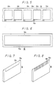
- the cover film 16 can be formed such that, for example, as shown in Figure 5, a cover film layer 16b comprising a transparent resinous layer releasable from a film base material 16a is intermittently coated on the film base material so as to have a pattern of the same shape and size as those of the respective ink portions Y, M, C and B of, for example, the ink ribbon 3.
- a similar cover film layer 16b can be continuously coated on the film base material 16a.
- the film base material 16a of the cover film 16 is made by coating a resinous composition for use in a smoothing treatment on condenser paper in order that the resinous layer serving as the cover film layer 16b can be transferred positively, that is with certainty.
- the resin for use in lamination may be one which has high transparency and improves the colouring property of the sublimation dye.
- the resinous materials must be selected so as to avoid the possibility that, upon transferring, the resin for use in lamination and the resin for use in smoothing treatment will be dissolved into each other and then made integral.
- the resin for use in smoothing treatment prefferably be one which will not melt together with the resin for use in lamination; for example, silicone resins, polyolefins (polyethylene, polypropylene and copolymers of various kinds) and acrylic resins may be employed.
- the resin for use in smoothing treatment was formed by mixing 100 parts by weight of a polybutadiene-system oligomer having terminal acrylic groups and 2 parts by weight of benzil dimethyl ketal (benzoyl-phenyl- dimethoxy-methane) as a photosensitiser and coating the mixed product on condenser paper so that it has a weight per unit area of 10 g/m 2 . Thereafter, the product was cured under irradiation from a high voltage mercury lamp of 80 W/ cm disposed at a distance of 10 cm from the coating for 10 seconds. As a result, the film base material 16a having the smooth coated surface was obtained.
- a saturated linear polyester resin was used for the resin for use in lamination, namely the cover film layer 16b.
- a saturated linear polyester resin was used for example, a mixture of VYLON No. 20 (60 parts by weight) and VYLON No. 30 (40 parts by weight), each manufactured by TOYOBO CO., LTD., was dissolved, so as to have a solid content of 30 weight %, in methyl ethyl ketone.
- This solution was coated on the film base material 16a so as to form the cover film layer 16b. In this case, the coating weight per unit area was 20 g/ m 2 .
- a mixture of 100 parts by weight of silicone rubber, 10 parts by weight of a catalyser and 30 parts by weight of toluene was used to form the resin for use in smoothing treatment.
- This mixture was coated on condenser paper (10 g/m 2 ) and then cured at 150°C for one hour.
- the resin for the cover film layer was formed by coating and then drying a 30% solution of VYLON No. 20, manufactured by TOYOBO CO., LTD., in methyl ethyl ketone.
- polyethylene (SUMIKATHENE L-402 manufactured by SUMITOMO CHEMICAL CO., LTD.) was employed as the resin for sue in smoothing treatment. Specifically, this polyethylene was press- moulded to form a film having a thickness of 10 micrometers by a unaxial injection moulding machine at a screw temperature ranging from 200 to 220°C and a die temperature of 220°C. The resultant polyethylene film was roll-laminated on condenser paper under a linear pressure of 3 kg/ cm, at a temperature of 140°C and at a speed of 3 m/min.
- the cover film layer 16b was formed on the film base material 16a with the surface smoothed in similar manner to the first example.
- HI-MILAN No. 1855 manufactured by MITSUI POLYCHEMICALS CO., LTD. can be used in place of the SUMIKATHENE L-402 manufactured by SUMITOMO CHEMICAL CO., LTD.
- the cover film layer 16b can be formed as a layer of desired thickness and having a sufficiently uniform and smooth surface, without considering how to avoid the influence exerted on these ink portions.
- the thermal head 19 for use in hot pressing the cover film 16 is provided at its tip end, as for example, shown in Figures 7 and 8, with a contact portion 19a of a thin plate shape which has a width covering the full width of the ink portions Y, M, C and B of the ink ribbon 3 and comes into line contact with the platen 2, with the ink ribbon 3 and the cover film 16 therebetween.
- a resistive material layer 19b is deposited on the contact portion 19a by, for example, vacuum evaporation, plating or the like so as to generate heat when it is supplied with a current.
- the resistive material layer 19b may, as shown in Figure 7, be formed continuously with a width corresponding to that of the ink portions of the ink ribbon 3, or, as shown in Figure 8, may be formed intermittently at portions corresponding to each head element 4a of the thermal transfer head 4 as shown in Figure 1.
- the cover film layer 16b of the cover film 16 is transferred and pressed on to the printing paper 1 by the thermal head 19 as mentioned above.
- a mark 16c is disposed in association with each intermittent pattern, just like the detection marks 5 formed on the ink ribbon 3 described in connection with Figure 1, and each mark 16c is detected by detecting means (not shown) so as to determine the position of the cover film 16b relative to the printing paper, thereby enabling the cover film layer 16b to be laminated on the printing paper 1 exactly at the printed portion.
- the thermal head 4 for use in printing and the thermal head 19 for use in hot pressing the cover film 16 are disposed at different positions with respect to the common platen 2 around which the printing paper 1 is wound, it is possible to avoid the apparatus having to be of large size due to the provision of press rolls, and to avoid the heat capacity from being increased and much energy thereby being consumed, and so on, as described in the introduction to this description.
- cover film 16 having the cover film layer 16b is formed independently of the ink ribbon 3, the constraint due to the ink portion, as mentioned in the introduction to this specification, can be avoided, and the cover film layer can be formed so as to have a desired thickness and coating condition, whereby the cover film layer can be printed on the printing paper positively, that is with certainty or reliably.
- the laminator driving mechanism becomes unnecessary, making the apparatus relatively small in size and simple in construction and reducing the power consumption remarkably. Furthermore, since the cover film 16 is hot- pressed by the thermal head 19, the heat capacity becomes very small, making instantaneous heating and/or cooling possible. Thus, in addition to the above-mentioned advantage that the apparatus can be made to be of small size and manpower can be saved, the responsiveness thereof can be made high and the handling thereof becomes easy.
- the cover film can be prevented from being wound around the rolls and also prevented from being dirtied, the large pressure can be made unnecessary, and bubbles can be prevented from being created, resulting in great practical advantages.
- Figures 9 and 10 illustrate respective further embodiments of the present invention.
- the ink ribbon 3 comprises the ink portions, for example the ink portions Y, M, C and B coated with the sublimation dyes of, for example, yellow, magenta cyan and the black, respectively, which are arranged in turn, and the cover film 13 made of the transparent resinous layer releasable from the base material 9 and located thereafter.
- the ink ribbon 3 is transferred from a supply roll 24 to a take-up roll 25 and in the midst of its movement, the ribbon 3 lies along the platen 2 around which the printing paper 1 is wound, coming into contact with the printing paper 1 disposed on the platen 2.
- the thermal transfer head 4 which has a number of heat generating elements heated in accordance with the picture information, comes into close contact with the ink ribbon 3 from its back surface so as sequentially to transfer the sublimation dyes of respective colours on to the printing paper, thereby obtaining the colour picture image.
- the thermal transfer head 4, the ink ribbon 3, the platen 2 and so on can be constructed similarly to those in Figure 1.
- the cover film 13 is moved in contact therewith and the cover film 13 is hot pressed on to the printing paper 1, which remains held on the platen 2, from the back surface of the cover film 13, by using the thermal head 19 having the single heat generating portion extending over its full width as shown in Figure 7.
- Guide members 27 and 28 are provided for the ink ribbon 3.
- the ink ribbon was heated from the back surface thereof by the thermal head 4 (having a number of heat generating elements for use in picture image formation in accordance with the video signal) so as to sublimate the sublimation dyes on to the surface of the printing paper 1, which was disposed on the platen 2, whereby the picture image was formed.
- the sublimation dyes may be yellow, magenta, cyan and necessary black and used in turn repeatedly.
- the thermal head 19 comes into contact with the cover film 13 formed on the ribbon 3 from the back surface thereof and is heated so as to hot melt and transfer the cover film 13. In this case, the position of the cover film 13 upon starting the lamination with respect to the position of the picture image was automatically determined. As a result, the cover film 13 was automatically released from the ribbon base material and a print was obtained that had a good finish and a very smooth surface.
- This embodiment uses an integral type head 29 in which the thermal head 4 for the picture image and the thermal head 19 having the single heat generating element for the cover film are disposed parallel to each other on a surface of a ceramic plate.
- the picture image thermal head 4 of the head 29 is inclined first to the surface of the printing paper 1 disposed on the platen 2 and is heated to heat the ink ribbon from the back surface side of the portion printed with the sublimation ink so as to sublimate the sublimation dye in accordance with the picture image information, thereby forming the picture image.
- the head 29 is oppositely inclined a little at the side of the thermal head 19 having the single heat generating element so that the element is in contact with the back surface of the ribbon sufficiently and heats the cover film 13 on the back surface of the ribbon so as to melt bond and transfer the cover film 13 on to the printing paper 1.
- the other parts of the printer of Figure 9 are formed similarly to those of Figure 1.
- the picture is printed by the multi-element thermal head which is heated in accordance with the picture image information under the condition that the sublimation dye portion of the ribbon is in close contact with the printing paper disposed on the platen to transfer the sublimation dye on to the printing paper thereby printing the picture image, and the thermal head having the single heat generating element over its full width is used for hot pressing the cover film on to the printing paper under the condition that the printing paper and the cover film are in close contact with each other on the platen and the ink ribbon coated with sublimation dye portions, the cover film being in a predetermined alignment.
- the lamination of the cover film can be carried out stably and positively (that is, with certainty or reliably) and the overall arrangement of the apparatus can be amde smaller in size and simpler in construction.
Landscapes
- Physics & Mathematics (AREA)
- Optics & Photonics (AREA)
- Electronic Switches (AREA)
- Thermal Transfer Or Thermal Recording In General (AREA)
- Impression-Transfer Materials And Handling Thereof (AREA)
- Accessory Devices And Overall Control Thereof (AREA)
Abstract
Claims (5)
caractérisé en ce que le dispositif de pressage à chaud de la pellicule de recouvrement (16, 13) comporte une tête thermique (19) ayant pour fonction de presser à chaud la pellicule de recouvrement sur le papier d'impression (1) portant l'image imprimée pendant que la papier reste maintenu sur le rouleau (2).
Applications Claiming Priority (4)
| Application Number | Priority Date | Filing Date | Title |
|---|---|---|---|
| JP98989/83 | 1983-06-27 | ||
| JP9898983U JPS605856U (ja) | 1983-06-27 | 1983-06-27 | プリンタ |
| JP9061184U JPS6120339U (ja) | 1984-06-18 | 1984-06-18 | プリンタ |
| JP90611/84 | 1984-06-18 |
Publications (3)
| Publication Number | Publication Date |
|---|---|
| EP0148276A4 EP0148276A4 (fr) | 1985-07-01 |
| EP0148276A1 EP0148276A1 (fr) | 1985-07-17 |
| EP0148276B1 true EP0148276B1 (fr) | 1988-01-13 |
Family
ID=26432076
Family Applications (1)
| Application Number | Title | Priority Date | Filing Date |
|---|---|---|---|
| EP19840902539 Expired EP0148276B1 (fr) | 1983-06-27 | 1984-06-26 | Imprimante |
Country Status (3)
| Country | Link |
|---|---|
| EP (1) | EP0148276B1 (fr) |
| DE (1) | DE3468652D1 (fr) |
| WO (1) | WO1985000144A1 (fr) |
Families Citing this family (9)
| Publication number | Priority date | Publication date | Assignee | Title |
|---|---|---|---|---|
| CA1284913C (fr) * | 1984-10-23 | 1991-06-18 | Mitsuhiro Shimada | Dispositif d'enregistrement thermique du type a transfert de chaleur |
| JP2565866B2 (ja) * | 1986-02-25 | 1996-12-18 | 大日本印刷株式会社 | 被熱転写シ−ト |
| CA1323982C (fr) * | 1986-07-14 | 1993-11-09 | Sadayuki Ohki | Element indicateur revetu d'une couche protectrice et procede de fabrication connexe |
| JPH0790665B2 (ja) * | 1986-08-27 | 1995-10-04 | 株式会社日立製作所 | 熱転写方法及びこれに用いる熱転写用インクシート |
| JP2741727B2 (ja) * | 1986-09-29 | 1998-04-22 | 株式会社日立製作所 | 熱転写記録装置 |
| US5009530A (en) * | 1987-10-31 | 1991-04-23 | Brother Kogyo Kabushiki Kaisha | Apparatus for reverse recording image and covering by protective medium |
| US5193926A (en) * | 1987-12-21 | 1993-03-16 | Brother Kogyo Kabushiki Kaisha | Apparatus for recording image covered by protective medium |
| GB8826455D0 (en) * | 1988-11-11 | 1988-12-14 | Ici Plc | Dyesheet |
| EP0518621B1 (fr) * | 1991-06-10 | 1996-12-11 | Tektronix Inc. | Procédé de traitement de substrates imprimés |
Family Cites Families (6)
| Publication number | Priority date | Publication date | Assignee | Title |
|---|---|---|---|---|
| DE3175309D1 (en) * | 1980-10-16 | 1986-10-16 | Fuji Xerox Co Ltd | Multi-colour image recording device |
| JPS57201686A (en) * | 1981-06-05 | 1982-12-10 | Sony Corp | Color printer |
| US4505975A (en) * | 1981-07-25 | 1985-03-19 | Sony Corporation | Thermal transfer printing method and printing paper therefor |
| JPS58148779A (ja) * | 1982-03-02 | 1983-09-03 | Sony Corp | 熱転写印刷方法 |
| JPS58148778A (ja) * | 1982-03-02 | 1983-09-03 | Sony Corp | 転写紙 |
| DE3315139A1 (de) * | 1982-04-28 | 1983-11-03 | Canon K.K., Tokyo | Aufzeichnungsgeraet |
-
1984
- 1984-06-26 EP EP19840902539 patent/EP0148276B1/fr not_active Expired
- 1984-06-26 WO PCT/JP1984/000330 patent/WO1985000144A1/fr active IP Right Grant
- 1984-06-26 DE DE8484902539T patent/DE3468652D1/de not_active Expired
Also Published As
| Publication number | Publication date |
|---|---|
| WO1985000144A1 (fr) | 1985-01-17 |
| EP0148276A4 (fr) | 1985-07-01 |
| EP0148276A1 (fr) | 1985-07-17 |
| DE3468652D1 (en) | 1988-02-18 |
Similar Documents
| Publication | Publication Date | Title |
|---|---|---|
| EP0160098B1 (fr) | Ruban encreur pour copie sur papier du type a transfert par sublimation | |
| EP0257633B2 (fr) | Procédé de transfert thermique et feuille d'encre de transfert thermique à utiliser pour le procédé | |
| EP0148276B1 (fr) | Imprimante | |
| US4518645A (en) | Transfer type heat sensitive recording medium | |
| EP1189761B1 (fr) | Procede d'impression par transfert thermique | |
| US4930417A (en) | Printer for simultaneously forming planographic printing surfaces and printing ink images | |
| JPS60225777A (ja) | 感熱転写記録用インクリボン | |
| US4775578A (en) | Colored ink ribbon of electrothermal transfer type for thermal printers | |
| JP4439717B2 (ja) | 転写物の製造方法 | |
| US6476842B1 (en) | Transfer printing | |
| US5424759A (en) | Dye rollers for laser thermal dye transfer | |
| JPH0139566Y2 (fr) | ||
| EP0427212A2 (fr) | Méthode et appareil pour l'enregistrement thermique par transfert du type ligne par ligne | |
| US6979488B2 (en) | Receiver having hydrophilic receiving surface | |
| JPH0564903A (ja) | 昇華式熱転写プリンター | |
| JP3483337B2 (ja) | 画像形成装置 | |
| US6055009A (en) | Re-inkable belt heating | |
| US4639742A (en) | Method and apparatus for printing an image | |
| WO1999062721A1 (fr) | Procede d'application d'une couche de base permettant l'impression | |
| WO1997010956A9 (fr) | Perfectionnements concernant l'impression par transfert | |
| JPH07242072A (ja) | 熱転写記録方法及び装置 | |
| JPH091944A (ja) | インクシート、及びインクシートを用いた熱転写記録方式 | |
| JPH04166377A (ja) | インクドナーフィルム及び転写型カラー画像記録装置 | |
| JPH0261911B2 (fr) | ||
| JPS60250968A (ja) | 熱記録プリンタ |
Legal Events
| Date | Code | Title | Description |
|---|---|---|---|
| PUAI | Public reference made under article 153(3) epc to a published international application that has entered the european phase |
Free format text: ORIGINAL CODE: 0009012 |
|
| 17P | Request for examination filed |
Effective date: 19850227 |
|
| AK | Designated contracting states |
Kind code of ref document: A1 Designated state(s): DE FR GB NL |
|
| 17Q | First examination report despatched |
Effective date: 19860905 |
|
| GRAA | (expected) grant |
Free format text: ORIGINAL CODE: 0009210 |
|
| AK | Designated contracting states |
Kind code of ref document: B1 Designated state(s): DE FR GB NL |
|
| REF | Corresponds to: |
Ref document number: 3468652 Country of ref document: DE Date of ref document: 19880218 |
|
| ET | Fr: translation filed | ||
| PLBE | No opposition filed within time limit |
Free format text: ORIGINAL CODE: 0009261 |
|
| STAA | Information on the status of an ep patent application or granted ep patent |
Free format text: STATUS: NO OPPOSITION FILED WITHIN TIME LIMIT |
|
| 26N | No opposition filed | ||
| PGFP | Annual fee paid to national office [announced via postgrant information from national office to epo] |
Ref country code: FR Payment date: 19940609 Year of fee payment: 11 |
|
| PGFP | Annual fee paid to national office [announced via postgrant information from national office to epo] |
Ref country code: DE Payment date: 19940622 Year of fee payment: 11 |
|
| PGFP | Annual fee paid to national office [announced via postgrant information from national office to epo] |
Ref country code: GB Payment date: 19940624 Year of fee payment: 11 |
|
| PGFP | Annual fee paid to national office [announced via postgrant information from national office to epo] |
Ref country code: NL Payment date: 19940630 Year of fee payment: 11 |
|
| PG25 | Lapsed in a contracting state [announced via postgrant information from national office to epo] |
Ref country code: GB Effective date: 19950626 |
|
| PG25 | Lapsed in a contracting state [announced via postgrant information from national office to epo] |
Ref country code: NL Effective date: 19960101 |
|
| GBPC | Gb: european patent ceased through non-payment of renewal fee |
Effective date: 19950626 |
|
| PG25 | Lapsed in a contracting state [announced via postgrant information from national office to epo] |
Ref country code: FR Effective date: 19960229 |
|
| NLV4 | Nl: lapsed or anulled due to non-payment of the annual fee |
Effective date: 19960101 |
|
| PG25 | Lapsed in a contracting state [announced via postgrant information from national office to epo] |
Ref country code: DE Effective date: 19960301 |
|
| REG | Reference to a national code |
Ref country code: FR Ref legal event code: ST |