EP0148131A1 - Kanüle zur Drainage einer Vena cava - Google Patents
Kanüle zur Drainage einer Vena cava Download PDFInfo
- Publication number
- EP0148131A1 EP0148131A1 EP84830206A EP84830206A EP0148131A1 EP 0148131 A1 EP0148131 A1 EP 0148131A1 EP 84830206 A EP84830206 A EP 84830206A EP 84830206 A EP84830206 A EP 84830206A EP 0148131 A1 EP0148131 A1 EP 0148131A1
- Authority
- EP
- European Patent Office
- Prior art keywords
- cannula
- sleeve
- vena cava
- drainage
- tip
- Prior art date
- Legal status (The legal status is an assumption and is not a legal conclusion. Google has not performed a legal analysis and makes no representation as to the accuracy of the status listed.)
- Withdrawn
Links
Images

Classifications
-
- A—HUMAN NECESSITIES
- A61—MEDICAL OR VETERINARY SCIENCE; HYGIENE
- A61M—DEVICES FOR INTRODUCING MEDIA INTO, OR ONTO, THE BODY; DEVICES FOR TRANSDUCING BODY MEDIA OR FOR TAKING MEDIA FROM THE BODY; DEVICES FOR PRODUCING OR ENDING SLEEP OR STUPOR
- A61M25/00—Catheters; Hollow probes
- A61M25/10—Balloon catheters
Definitions
- the present invention concerns the cannulae for the drainage of the venous blood from the venae cavae towards a machine for an extracorporeal blood circulation.
- a cardio-pulmonary machine i.e. of an apparatus which is able to replace the functions of the heart and of the lungs of the patient during surgical operations on the heart.
- the venous blood of the patient is diverted from his venae cavae into the venous line of the cardio-pulmonary machine.
- the blood which is oxygenated inside this machine is then fed again by this machine towards the arterial system of the blood circulation apparatus of the patient.
- it is necessary that all the venous blood is conveyed to the machine so as to leave the heart entirely without blood and therefore ready for any surgical operation on opened heart.
- said drainage of the venous blood is, usually, obtained by means of the insertion of two cannulae or catheters in the superior and inferior vena cava respectively, each cannula passing through an incision made by the surgeon through the wall of the right atrium of the heart.
- the oxygenated blood is returned again in an artery of the patient through a third cannula.
- the cannula or catheter for the venous blood hitherto used consists of a tube which may be less or more flexible, which is made of plastics and which has a straight axis or an axis bent at right angle; the distal end of this cannula which will be inserted into a vena cava, ends with a tip in the form of a flute mouth or of a wedge- -shaped extensively slotted tip. At the opposite end of the cannula, this latter is connected to the intake duct of an extracorporeal circulation apparatus.
- caval cannulae of different forms and dimensions, some of which are provided, in a portion of their wall, with a stainless steel wire helically wound round them, acting as reinforcing means.
- the binding of the venae cavae requires a series of subsequent maneuvers, ae will be thereinafter better described, with reference to the incannulation of the superior vena cava.
- the binding of the inferior vena cava is carried out in a similar manner.
- the vena cava is sidely displaced and the auricle is lowered in order to explore the medial edge of the vena.
- the mesoderma of the vena cava will be then held tight at its postero-medial edge which is cut with the shears.
- a dissector gently maneuvered from the ouside towards the inside the rear edge of the vena cava is cut down. The tip of the dissector is caused to come out medially in the previously cut point, so that the dissector can be passed round the vessel in the rear part thereof.
- this dissector By means of this dissector an end of the ribbon is grasped, so that, as the dissector is retracted, it can be let pass behind the vena cava. The maneuver for causing the ribbon slipping must be accompanied with the surgeon's fingers. The two ends of this ribbon is then joined one to the other, thus completing the binding of the superior vena eava. Subsequently the ribbon is inserted within a small tube of caoutchouc, this operation being necessary in order to enable to tighten or release the loop formed by the ribbon.
- Said ribbon insertion comprises the following steps: the laying of the two end portions of the ribbon on the longitudinal groove of a metal grooved guide having a width lightly lesser than the inner diameter of the small tube of caoutchouc designed to receive and restrain the ribbon end portion to be inserted into said tube; the sliding of said ribbon in the inside of said caoutchouc tube with the simultaneous retraction of said metal guide; and, at last, the anchoring of said ribbon end portions by small Klemmer pliers.
- a superior and an inferior caval cannulae are inserted by means of an atriotomy which is carried out, according to the known technique.
- the already aforemontioned total or partial drainage of the venous blood is carried out. From what has been set forth, it will be understood that, if a controlled drainage has to be obtained, using the cannulae available, at present, on the market, a tying round of each of the vena cava becomes absolutely necessary.
- the present invention provides a cannula for the caval drainage, which does not require such a tying operation.
- the cannula consists of a tube having the typical features of any known caval cannula, but which is provided, near the tip portion thereof, with an outer expansion locking device, including an inflatable annular cavity created between the outer surface of the cannula and the inner surface of a shaped sleeve made of an elastically deformable material and fixed, along its peripheral edges, to the outer surface of the cannula, said cavity being connected with an external source of a pressurized fluid by means of a thin pipe, the first length of which passes through the thickness of the cannula body in a longitudinal direction while the second length comes out from said wall.
- 1 or la respectively indicate a tube forming a cannula
- 2 is a sleeve applied around the cannula 1 or la, so aa to define therebetween an annular cavity 12 of a variable volume
- the tube 1 which is made of a semi-rigid plastic material compatible with the human organism, as, for instance, polyvinyl chloride, is straight.
- Its end portion 3, which is designed to be inserted into the vena cava has a tip 3a shaped as a flute mouth and obtained by means of a cut oblique to the axis of the tube 1.
- the tube 1 is shaped as a female element 5 of a bell-and-spigot joint provided for the connection of the cannula 1 with conduit (not shown) of the venous line of a cardio--pulmonary machine.
- a sleeve 2 is mounted made of an elastically deformable material, rubber, for instance.
- the peripheral edges 2a of said sleeve 2 are fixed by adhesive means to the outer surface of the tube 1 so as to define therebetween the apace or chamber 12 of variable volume which is connected by means a thin pipe which comprises a first length which pass inside the thickness of the tube 1 in a longitudinal direction, and a second length 6a which travels out of the cannula 1, and in which a pressure gauge 7 is inserted, aa for instance, an inflatable caoutchouc ballonet.
- the length 6a of said pipe 6, 6a will be connected with a source of a pressurized fluid, as for instance, a physiologic solution, since said fluid cannot cause any damage to the patient in the event of accidental breakages in any point of this small hydraulic plant.
- a simple syringe is sufficient.
- the outer length 6a of the pipe 6, 6a can be easily squeezed between the two arm elements of a clamp so as to stop any fluid return and prevent the deflation of said inner apace 12.
- the inflation of the ballonet 7 indicates the inflation condition of the inner annular space 12 and thus the expanded condition of the sleeve 3.
- Fig. 2 a second embodiment is shown of the cannula according to the present invention.
- the tube la is bent at a substantially right angle. Its portion 3 comprised between the tip 3a and the sleeve 2 is provided with radial orifices 4 which are needed for increasing the blood inlet area.
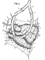
- Figure 4 diagrammatically shows the use of two straight cannulae 1 constructed according to the first embodiment.
- C s indicates the superior vena cava
- C i the inferior vena cava
- A is the atrium.
- the present procedure for the incannulation will be now described with reference to the inferior vena cava C i .
- vessel pliers By means of vessel pliers the atrial appendage is raised and is clamped near its base by an angiostate or vessel clamp. A purse-suture is obtained above the angiostate.
- the ends of the thread 8 used to form the purse are locked into the clamping arms of a so called “tourniquet” or twisting device. Then the atrial appendage is grasped again with the veasel clamp and after having temporarily opened wide apart the arms of the angiostate, a dose of heparine is introduced in the area forming the purse.
- the atrial wall is incised in the area delimitated by said purse zone.
- the surgical orifice is then exposed, grasping the edges thereof by means of the arms of a vessel pliers. Row all is ready for the insertion of the cannula 1 into the atrium orifice 13.
- the tip 3a of the cannula 1 is inserted in the cut 13 and then the end portion 3 of said cannula 1 is pushed forwards more and more, until said portion 3 with the sleeve 2, in deflated condition, attains its correct positioning, after having snap spread apart the angiostate.
- the cannula I is fixed to the tourniquet by means of a strong lace 9.
- the two caval cannulae are connected by means of a rigid Y-pipe union 10 to the venous line of extracorporeal circuit of a cardio-pulmonary machine.
- the annular spaces 12 of the aleeve devices are now inflated by the pressurised fluid and then the flexible pipe portion 6a is squeezed by means of a clamp 11.
- the walls of the sleeves 2 are elastically and radially deformed so as to sharply press against the caval walls.
- a seal contact between the caval wall and the respective cannula is attained and therefore the total deviation of the venous blood is obtained.
- the clamps 11 are removed so that the flexible sleeves 2 of the expansion locking devices are deflated, by the discharge of the pressurized fluid out of the end of the pipe length 6a.
- the lace 9 which fixes the cannula 1 is cut, while the angiostate is leaned against the atrium base.
- the cannula 1 is quickly slipped out after having released the thread 8 of the purse-suture, while simultaneously the operator closes the surgical orifice 13 with the angiostate.
Applications Claiming Priority (2)
| Application Number | Priority Date | Filing Date | Title |
|---|---|---|---|
| IT48686/83A IT1197675B (it) | 1983-07-13 | 1983-07-13 | Cannula di drenaggio cavale,per l'impianto della circolazione extra corporea,dotata di manicotto gonfiabile di tenuta |
| IT4868683 | 1983-07-13 |
Publications (1)
| Publication Number | Publication Date |
|---|---|
| EP0148131A1 true EP0148131A1 (de) | 1985-07-10 |
Family
ID=11268041
Family Applications (1)
| Application Number | Title | Priority Date | Filing Date |
|---|---|---|---|
| EP84830206A Withdrawn EP0148131A1 (de) | 1983-07-13 | 1984-07-05 | Kanüle zur Drainage einer Vena cava |
Country Status (2)
| Country | Link |
|---|---|
| EP (1) | EP0148131A1 (de) |
| IT (1) | IT1197675B (de) |
Cited By (8)
| Publication number | Priority date | Publication date | Assignee | Title |
|---|---|---|---|---|
| EP0218275A1 (de) * | 1985-08-30 | 1987-04-15 | Fijneman, Martinus Jacobus Antonius Johannes | Mehrzweckkatheter |
| EP0280225A2 (de) * | 1987-02-25 | 1988-08-31 | Cardiosistemi S.P.A. | Dränier-Kanüle für Venen |
| AU621009B2 (en) * | 1989-10-31 | 1992-02-27 | Dideco S.R.L. | Device for conveying blood flow during liver surgery |
| US5106363A (en) * | 1988-10-11 | 1992-04-21 | Terumo Kabushiki Kaisha | Blood perfusion system and tube used therein |
| ES2055671A1 (es) * | 1993-09-16 | 1994-08-16 | Biomed S A | Canula pseudoauricular. |
| EP0636383A1 (de) * | 1993-06-30 | 1995-02-01 | Takao Ishimura | Verfahren zur Angiographie |
| WO1997039789A1 (en) * | 1996-04-22 | 1997-10-30 | Medtronic, Inc. | Two-stage angled venous cannula |
| US6866650B2 (en) | 1991-07-16 | 2005-03-15 | Heartport, Inc. | System for cardiac procedures |
Citations (11)
| Publication number | Priority date | Publication date | Assignee | Title |
|---|---|---|---|---|
| GB1026755A (en) * | 1963-01-04 | 1966-04-20 | Frederic Eugene Basil Foley | Bag catheters |
| GB1058888A (en) * | 1963-08-17 | 1967-02-15 | Werner Ruesch | Endotracheal catheter |
| US3407817A (en) * | 1965-07-26 | 1968-10-29 | Air Reduction Inc | Catheter with cuff inflater and indicator |
| GB1186964A (en) * | 1967-03-20 | 1970-04-08 | Roland Leon Tindel | Endotracheal Tubes. |
| US3602226A (en) * | 1965-11-19 | 1971-08-31 | Kendall & Co | Self-inflating catheter with means to prevent loss of inflation fluid |
| US3734100A (en) * | 1973-05-07 | 1973-05-22 | Medical Products Corp | Catheter tubes |
| US3890976A (en) * | 1972-10-26 | 1975-06-24 | Medical Products Corp | Catheter tip assembly |
| US3971385A (en) * | 1974-09-09 | 1976-07-27 | Sherwood Medical Industries Inc. | Medical tube with cuff |
| FR2297640A1 (fr) * | 1975-01-15 | 1976-08-13 | Rhone Poulenc Ind | Catheter |
| GB2047538A (en) * | 1979-04-30 | 1980-12-03 | Int Paper Co | Self-inflating urinary catheter |
| US4324235A (en) * | 1980-03-24 | 1982-04-13 | Beran Anthony V | Endotracheal tube |
-
1983
- 1983-07-13 IT IT48686/83A patent/IT1197675B/it active
-
1984
- 1984-07-05 EP EP84830206A patent/EP0148131A1/de not_active Withdrawn
Patent Citations (11)
| Publication number | Priority date | Publication date | Assignee | Title |
|---|---|---|---|---|
| GB1026755A (en) * | 1963-01-04 | 1966-04-20 | Frederic Eugene Basil Foley | Bag catheters |
| GB1058888A (en) * | 1963-08-17 | 1967-02-15 | Werner Ruesch | Endotracheal catheter |
| US3407817A (en) * | 1965-07-26 | 1968-10-29 | Air Reduction Inc | Catheter with cuff inflater and indicator |
| US3602226A (en) * | 1965-11-19 | 1971-08-31 | Kendall & Co | Self-inflating catheter with means to prevent loss of inflation fluid |
| GB1186964A (en) * | 1967-03-20 | 1970-04-08 | Roland Leon Tindel | Endotracheal Tubes. |
| US3890976A (en) * | 1972-10-26 | 1975-06-24 | Medical Products Corp | Catheter tip assembly |
| US3734100A (en) * | 1973-05-07 | 1973-05-22 | Medical Products Corp | Catheter tubes |
| US3971385A (en) * | 1974-09-09 | 1976-07-27 | Sherwood Medical Industries Inc. | Medical tube with cuff |
| FR2297640A1 (fr) * | 1975-01-15 | 1976-08-13 | Rhone Poulenc Ind | Catheter |
| GB2047538A (en) * | 1979-04-30 | 1980-12-03 | Int Paper Co | Self-inflating urinary catheter |
| US4324235A (en) * | 1980-03-24 | 1982-04-13 | Beran Anthony V | Endotracheal tube |
Cited By (9)
| Publication number | Priority date | Publication date | Assignee | Title |
|---|---|---|---|---|
| EP0218275A1 (de) * | 1985-08-30 | 1987-04-15 | Fijneman, Martinus Jacobus Antonius Johannes | Mehrzweckkatheter |
| EP0280225A2 (de) * | 1987-02-25 | 1988-08-31 | Cardiosistemi S.P.A. | Dränier-Kanüle für Venen |
| EP0280225A3 (de) * | 1987-02-25 | 1989-03-15 | Cardiosistemi S.P.A. | Dränier-Kanüle für Venen |
| US5106363A (en) * | 1988-10-11 | 1992-04-21 | Terumo Kabushiki Kaisha | Blood perfusion system and tube used therein |
| AU621009B2 (en) * | 1989-10-31 | 1992-02-27 | Dideco S.R.L. | Device for conveying blood flow during liver surgery |
| US6866650B2 (en) | 1991-07-16 | 2005-03-15 | Heartport, Inc. | System for cardiac procedures |
| EP0636383A1 (de) * | 1993-06-30 | 1995-02-01 | Takao Ishimura | Verfahren zur Angiographie |
| ES2055671A1 (es) * | 1993-09-16 | 1994-08-16 | Biomed S A | Canula pseudoauricular. |
| WO1997039789A1 (en) * | 1996-04-22 | 1997-10-30 | Medtronic, Inc. | Two-stage angled venous cannula |
Also Published As
| Publication number | Publication date |
|---|---|
| IT8348686A0 (it) | 1983-07-13 |
| IT1197675B (it) | 1988-12-06 |
Similar Documents
| Publication | Publication Date | Title |
|---|---|---|
| JP4334022B2 (ja) | 患者の上行大動脈を閉塞する方法および装置 | |
| US6500145B1 (en) | Retrograde cardioplegia catheter | |
| US4639252A (en) | Venous return catheter | |
| US5925054A (en) | Perfusion device for maintaining blood flow in a vessel while isolating an anastomosis | |
| US5423745A (en) | Irregular surface balloon catheters for body passageways and methods of use | |
| US5505698A (en) | Cardioplegia catheter with elongated cuff | |
| US4287892A (en) | Cannula for intra-aortic balloon devices and the like | |
| JP3107397B2 (ja) | 移植用器具及び移植用器具の折り曲げ方法 | |
| US4122858A (en) | Adapter for intra-aortic balloons and the like | |
| CA2354628C (en) | Improved intra-aortic balloon catheter and insertion sheath | |
| US4741328A (en) | Means for intraaortic assist and method of positioning a catheter therefor | |
| US5967988A (en) | Catheter having echogenicity enhancement | |
| US5158545A (en) | Diameter expansion cannula | |
| US5599329A (en) | Multi purpose perfusion cannula | |
| US5634941A (en) | Vascular graft bypass apparatus | |
| EP0280225A2 (de) | Dränier-Kanüle für Venen | |
| JPH02295566A (ja) | バルーン付カテーテル | |
| JP2012228531A (ja) | 案内用鞘とカテーテルとの組合せ | |
| WO2002036019A9 (en) | System, devices and methods for deploying suturing needles | |
| EP0148131A1 (de) | Kanüle zur Drainage einer Vena cava | |
| EP0983027A1 (de) | Vorrichtung zur teilweisen okklusion von blutgefässen | |
| CN110314014A (zh) | 血管支架及其牵引装置 | |
| JPH11335A (ja) | 血管吻合補助具 | |
| US6626914B2 (en) | Graft connector, an introducer therefor and a method of making a branch connection | |
| CN208851712U (zh) | 血管支架及其牵引装置 |
Legal Events
| Date | Code | Title | Description |
|---|---|---|---|
| PUAI | Public reference made under article 153(3) epc to a published international application that has entered the european phase |
Free format text: ORIGINAL CODE: 0009012 |
|
| AK | Designated contracting states |
Designated state(s): AT BE CH DE FR GB LI LU NL SE |
|
| STAA | Information on the status of an ep patent application or granted ep patent |
Free format text: STATUS: THE APPLICATION IS DEEMED TO BE WITHDRAWN |
|
| 18D | Application deemed to be withdrawn |
Effective date: 19860311 |
|
| RIN1 | Information on inventor provided before grant (corrected) |
Inventor name: PASQUI, UGO |