EP0148039A1 - Einrichtung zum Verbinden zweier Teile durch einen nichtverlierbaren Bolzen und entsprechendes Verbindungsverfahren - Google Patents
Einrichtung zum Verbinden zweier Teile durch einen nichtverlierbaren Bolzen und entsprechendes Verbindungsverfahren Download PDFInfo
- Publication number
- EP0148039A1 EP0148039A1 EP84402159A EP84402159A EP0148039A1 EP 0148039 A1 EP0148039 A1 EP 0148039A1 EP 84402159 A EP84402159 A EP 84402159A EP 84402159 A EP84402159 A EP 84402159A EP 0148039 A1 EP0148039 A1 EP 0148039A1
- Authority
- EP
- European Patent Office
- Prior art keywords
- screw
- rod
- hole
- parts
- locking
- Prior art date
- Legal status (The legal status is an assumption and is not a legal conclusion. Google has not performed a legal analysis and makes no representation as to the accuracy of the status listed.)
- Granted
Links
- 238000000034 method Methods 0.000 title claims abstract description 7
- XLYOFNOQVPJJNP-UHFFFAOYSA-N water Substances O XLYOFNOQVPJJNP-UHFFFAOYSA-N 0.000 claims abstract description 13
- 238000005192 partition Methods 0.000 claims description 21
- 230000000903 blocking effect Effects 0.000 claims description 7
- 238000002788 crimping Methods 0.000 claims description 5
- 238000006073 displacement reaction Methods 0.000 claims description 5
- 230000006835 compression Effects 0.000 claims description 3
- 238000007906 compression Methods 0.000 claims description 3
- 238000000638 solvent extraction Methods 0.000 abstract description 8
- 230000000712 assembly Effects 0.000 description 5
- 238000000429 assembly Methods 0.000 description 5
- 241001080024 Telles Species 0.000 description 2
- 239000000498 cooling water Substances 0.000 description 2
- 239000000446 fuel Substances 0.000 description 2
- 230000002093 peripheral effect Effects 0.000 description 2
- 240000008042 Zea mays Species 0.000 description 1
- 238000001816 cooling Methods 0.000 description 1
- 239000011258 core-shell material Substances 0.000 description 1
- 230000006866 deterioration Effects 0.000 description 1
- 230000000694 effects Effects 0.000 description 1
- 239000002184 metal Substances 0.000 description 1
- 230000035515 penetration Effects 0.000 description 1
- 230000008646 thermal stress Effects 0.000 description 1
Images

Classifications
-
- F—MECHANICAL ENGINEERING; LIGHTING; HEATING; WEAPONS; BLASTING
- F16—ENGINEERING ELEMENTS AND UNITS; GENERAL MEASURES FOR PRODUCING AND MAINTAINING EFFECTIVE FUNCTIONING OF MACHINES OR INSTALLATIONS; THERMAL INSULATION IN GENERAL
- F16B—DEVICES FOR FASTENING OR SECURING CONSTRUCTIONAL ELEMENTS OR MACHINE PARTS TOGETHER, e.g. NAILS, BOLTS, CIRCLIPS, CLAMPS, CLIPS OR WEDGES; JOINTS OR JOINTING
- F16B29/00—Screwed connection with deformation of nut or auxiliary member while fastening
-
- F—MECHANICAL ENGINEERING; LIGHTING; HEATING; WEAPONS; BLASTING
- F16—ENGINEERING ELEMENTS AND UNITS; GENERAL MEASURES FOR PRODUCING AND MAINTAINING EFFECTIVE FUNCTIONING OF MACHINES OR INSTALLATIONS; THERMAL INSULATION IN GENERAL
- F16B—DEVICES FOR FASTENING OR SECURING CONSTRUCTIONAL ELEMENTS OR MACHINE PARTS TOGETHER, e.g. NAILS, BOLTS, CIRCLIPS, CLAMPS, CLIPS OR WEDGES; JOINTS OR JOINTING
- F16B39/00—Locking of screws, bolts or nuts
- F16B39/02—Locking of screws, bolts or nuts in which the locking takes place after screwing down
- F16B39/04—Locking of screws, bolts or nuts in which the locking takes place after screwing down with a member penetrating the screw-threaded surface of at least one part, e.g. a pin, a wedge, cotter-pin, screw
-
- F—MECHANICAL ENGINEERING; LIGHTING; HEATING; WEAPONS; BLASTING
- F16—ENGINEERING ELEMENTS AND UNITS; GENERAL MEASURES FOR PRODUCING AND MAINTAINING EFFECTIVE FUNCTIONING OF MACHINES OR INSTALLATIONS; THERMAL INSULATION IN GENERAL
- F16B—DEVICES FOR FASTENING OR SECURING CONSTRUCTIONAL ELEMENTS OR MACHINE PARTS TOGETHER, e.g. NAILS, BOLTS, CIRCLIPS, CLAMPS, CLIPS OR WEDGES; JOINTS OR JOINTING
- F16B21/00—Means for preventing relative axial movement of a pin, spigot, shaft or the like and a member surrounding it; Stud-and-socket releasable fastenings
- F16B21/10—Means for preventing relative axial movement of a pin, spigot, shaft or the like and a member surrounding it; Stud-and-socket releasable fastenings by separate parts
- F16B21/16—Means for preventing relative axial movement of a pin, spigot, shaft or the like and a member surrounding it; Stud-and-socket releasable fastenings by separate parts with grooves or notches in the pin or shaft
- F16B21/165—Means for preventing relative axial movement of a pin, spigot, shaft or the like and a member surrounding it; Stud-and-socket releasable fastenings by separate parts with grooves or notches in the pin or shaft with balls or rollers
-
- F—MECHANICAL ENGINEERING; LIGHTING; HEATING; WEAPONS; BLASTING
- F16—ENGINEERING ELEMENTS AND UNITS; GENERAL MEASURES FOR PRODUCING AND MAINTAINING EFFECTIVE FUNCTIONING OF MACHINES OR INSTALLATIONS; THERMAL INSULATION IN GENERAL
- F16B—DEVICES FOR FASTENING OR SECURING CONSTRUCTIONAL ELEMENTS OR MACHINE PARTS TOGETHER, e.g. NAILS, BOLTS, CIRCLIPS, CLAMPS, CLIPS OR WEDGES; JOINTS OR JOINTING
- F16B41/00—Measures against loss of bolts, nuts, or pins; Measures against unauthorised operation of bolts, nuts or pins
- F16B41/002—Measures against loss of bolts, nuts or pins
Definitions
- the invention relates to a device for fixing two parts by captive screw and the corresponding fixing method.
- the core is constituted by a set of prismatic fuel assemblies arranged vertically and side by side and generally surrounded by a peripheral partitioning which matches the external shape of the core.
- This partitioning makes it possible in particular to maintain the assemblies of the core and to channel the water under pressure towards the base of the core, before crossing it from bottom to top.
- the partitioning of the core of a pressurized water nuclear reactor generally comprises a set of vertical plates assembled at right angles and holding devices constituted by horizontal plates cut according to the shape of the section of the core and interposed between all of the vertical plates of the partitioning and the ferrule of heart.
- This process consists in securing the partitions two by two by a set of through screws and based on one of the partitions and screwed inside a tapped hole made in the other partition.
- Screw braking devices are known by washers or keying but these known devices do not provide absolute security and are difficult to implement in the case of a screw inserted inside the partitions of the core of a nuclear reactor.
- a device has also been proposed (US-A-3,390,712) for locking a screw by elements movable in the radial direction in housings passing through the threaded part of the screw and communicating with a central bore provided over the entire length. of the screw.
- a locking rod slidingly mounted in the central bore of the screw makes it possible to move the mobile elements to put them in the locking position when the screw is in place in a tapped hole.
- the locking elements which comprise portions of threads with a pitch corresponding to that of the thread in which the screw is engaged must be in exact coincidence with the threads of the thread to come into the locking position by displacement of the rod. This exact coincidence is difficult if not impossible to achieve in the case of fixing screws for partitions of a pressurized water nuclear reactor.
- the locking rod is not fixed on the screw so as to prohibit any possibility of displacement and therefore of unlocking.
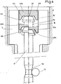
- FIG 1 we see the partitions 1 and 2 assembled in which is machined a hole 3 tapped on a part 3a of its length inside the partition 2. Inside the partition 1, the hole has a widening finished by a shoulder intended to receive the head of screw.
- the screw 5 has a threaded part 5a corresponding to the threaded part 3a of the hole inside the partition 2.
- the screw 5 is pierced with an axial bore 6 over its entire length and has a head 7 with a large diameter.
- the head 7 has an opening 8 of prismatic shape with a hexagonal section for the engagement of a screwing tool.
- Two radial direction holes 10 communicate with the central bore 6 of the screw at one of their ends and open at their other end onto the threaded external lateral surface 5a of the screw. Inside each of the holes 10 is arranged a ball 11, the diameter of which, as can be seen in FIG. 3a, is substantially equal to the maximum thickness of the tubular wall of the screw in its threaded part 5a.
- the rod 14 Inside the bore 6 of the screw is arranged a rod 14 engaged in this bore practically without play.
- the rod 14 comprises a head 15 whose diameter is substantially greater than the diameter of the bore 6 and a diameter part reduced 16 visible on the lower part of FIG. 4 on a larger scale, at its end opposite to the head 15.
- the reduced diameter part 16 is connected to the non reduced diameter part of the rod by a frustoconical surface.
- the reduced diameter part has a toroidal shape allowing it to come into contact with the balls 11, when the rod 14 is in its position shown in FIG. 1 or in the lower part of FIG. 4.
- the balls can come into the retracted position in the radial direction during the screwing of the screw 5 which causes the movement towards the inside of the balls 11 repelled by the threads of the tapped part 3a of the hole 3.
- the screw is put in place and screwed inside the tapped hole 3 by a tool whose external profile corresponds to the profile of the opening 8 of the screw head.
- the screw At the end of screwing, the screw is in its position shown in FIG. 2 where it ensures the closing of the gap between the partitions 1 and 2.
- This crimping tool 20 is designed so that it can be adapted on a device as described in French patent application No. 81 -14899 of July 30, 1981. As indicated, this tool has a prismatic external surface of a shape corresponding to the shape of the opening 8 of the screw head 7. Its lower part has a flat bearing surface 21, a bearing frustoconical 22 and a chamfer 23 making it easier to introduce it into the opening 8 of the screw head 7.
- the pressure on the balls is exerted by the frustoconical ramp located at the end of the reduced diameter zone.
- the radial advance of the balls towards the outside produces a crushing of the threads of the tapped part 3a of the hole 3, which causes a blocking in rotation and in translation of the screw.
- the tool 20 is then passed from position 20a to position 20b shown in FIG. 4. In its position 20b, the tool comes into contact through its frustoconical part 22 with the deformable parts 18 of the screw head 7.
- the deformable parts 18 are brought down until to bring them into a folded position 18b where they hold the head 15 of the operating rod against the bottom of the opening of the screw head.
- the fixing device is then in its blocking position shown in FIG. 3.
- the locking of the screw was obtained without deformation of this screw but simply by crushing the thread of the tapped hole in one of the partitions sounds on a very small surface corresponding to the contact surface with the ball.
- the balls are held in the locking position by the rod which is itself crimped on the screw.
- the means for blocking the screw can be different from spherical parts such as the balls 11 which have been described, these blocking means can be in the form of small cylinders whose end is rounded or any other suitable form. .
- the reduced diameter zone of the operating rod can have any shape facilitating the positioning of the operating rod in the locked position.
- the screw may have a single hole such as 10 which can receive a locking means, two holes arranged in opposite manner as in the embodiment which has been described, or three or more holes placed in angular positions regularly spaced around the axis of the screw.
- the fixing device according to the invention can be used outside the field of eliminating leakage spaces in the partitioning of a pressurized water nuclear reactor.
Landscapes
- Engineering & Computer Science (AREA)
- General Engineering & Computer Science (AREA)
- Mechanical Engineering (AREA)
- Clamps And Clips (AREA)
- Monitoring And Testing Of Nuclear Reactors (AREA)
- Connection Of Plates (AREA)
- Analysing Materials By The Use Of Radiation (AREA)
- Seeds, Soups, And Other Foods (AREA)
Applications Claiming Priority (2)
| Application Number | Priority Date | Filing Date | Title |
|---|---|---|---|
| FR8317279A FR2554185B1 (fr) | 1983-10-28 | 1983-10-28 | Dispositif de fixation de deux pieces par vis imperdable et procede de fixation correspondant |
| FR8317279 | 1983-10-28 |
Publications (2)
| Publication Number | Publication Date |
|---|---|
| EP0148039A1 true EP0148039A1 (de) | 1985-07-10 |
| EP0148039B1 EP0148039B1 (de) | 1988-03-16 |
Family
ID=9293649
Family Applications (1)
| Application Number | Title | Priority Date | Filing Date |
|---|---|---|---|
| EP84402159A Expired EP0148039B1 (de) | 1983-10-28 | 1984-10-26 | Einrichtung zum Verbinden zweier Teile durch einen nichtverlierbaren Bolzen und entsprechendes Verbindungsverfahren |
Country Status (8)
| Country | Link |
|---|---|
| US (1) | US4681495A (de) |
| EP (1) | EP0148039B1 (de) |
| JP (1) | JPS60104810A (de) |
| KR (1) | KR850003771A (de) |
| CA (1) | CA1221477A (de) |
| DE (1) | DE3469943D1 (de) |
| ES (1) | ES296247Y (de) |
| FR (1) | FR2554185B1 (de) |
Cited By (1)
| Publication number | Priority date | Publication date | Assignee | Title |
|---|---|---|---|---|
| EP0647496A3 (de) * | 1991-11-15 | 1995-08-16 | Demmeler Maschinenbau | Bolzen. |
Families Citing this family (25)
| Publication number | Priority date | Publication date | Assignee | Title |
|---|---|---|---|---|
| US4850774A (en) * | 1987-10-26 | 1989-07-25 | The Boeing Company | Self-locking adjustable screw |
| US4843792A (en) * | 1988-06-27 | 1989-07-04 | Stageright Corporation | Socket support and interlock for staging panels |
| FR2721665B1 (fr) * | 1994-06-22 | 1996-07-19 | Snecma | Ecrous ou vis de freinage et assemblages ainsi constitués. |
| US5931621A (en) * | 1998-04-20 | 1999-08-03 | Lucent Technologies Inc | Locking mechanism for a rotatable fastener |
| DE19945295C1 (de) * | 1999-09-22 | 2001-01-25 | Jac Products Deutschland Gmbh | Stützfuss für eine Fahrzeugdachreling |
| US6595714B2 (en) * | 2000-12-09 | 2003-07-22 | Tyee Aircraft | Swivel insert for a control rod |
| US6644903B1 (en) | 2001-06-12 | 2003-11-11 | Matdan America Corp. | Captive fastener with gradient hardened ferrule |
| US20060287166A1 (en) * | 2005-06-17 | 2006-12-21 | Alvarez Enrique L | Anchor system for use in an aquatic environment |
| US7458558B1 (en) | 2006-01-23 | 2008-12-02 | Patricia Toth | Controlled method and apparatus for releasing pressure |
| DE102006053141B3 (de) * | 2006-11-10 | 2008-06-19 | Atlas Copco Mai Gmbh | Verbesserter Gleitanker |
| RU2488335C2 (ru) | 2007-12-12 | 2013-07-27 | Нестек С.А. | Приемник использованных капсул или контейнеров машин для приготовления жидкой пищи или напитков |
| EP2070454B1 (de) | 2007-12-12 | 2015-07-15 | Nestec S.A. | Modulare Herstellung von Getränkeherstellungsmaschinen |
| PT2247827E (pt) * | 2008-02-29 | 2011-09-30 | Atlas Copco Mai Gmbh | Âncora deslizante melhorada |
| US8313066B2 (en) * | 2008-06-25 | 2012-11-20 | Medline Industries, Inc. | Intravenous fluid container stand and methods for making same |
| US20140352544A1 (en) | 2011-09-16 | 2014-12-04 | Alfred Yoakim | Clean multi-system beverage machine |
| WO2013037781A1 (en) | 2011-09-16 | 2013-03-21 | Nestec S.A. | Multi-system beverage machine multiple connections |
| RU2014115205A (ru) | 2011-09-16 | 2015-10-27 | Нестек С.А. | Безопасное соединительное устройство многосистемной машины для приготовления напитков |
| CN108691877A (zh) * | 2017-04-10 | 2018-10-23 | 杨光明 | 自锁紧紧固件及其锁紧方法 |
| US10385909B2 (en) * | 2017-07-26 | 2019-08-20 | Core Bolt Co., Ltd. | Bolt structure having locking unit embedded therein |
| CN111107770A (zh) | 2017-09-25 | 2020-05-05 | 雀巢产品有限公司 | 具有模块性的饮料机器 |
| PT3687347T (pt) | 2017-09-25 | 2023-09-07 | Nestle Sa | Máquinas de bebidas com um módulo removível |
| CN109519463B (zh) * | 2018-11-14 | 2020-08-28 | 苏州剑派实业有限公司 | 一种自锁螺栓 |
| RU2020103575A (ru) | 2020-01-28 | 2021-07-28 | Зе Боинг Компани | Регулируемые узлы соединительных тяг, имеющие шарнирный конец, и соответствующие способы |
| CN113374772A (zh) * | 2021-05-26 | 2021-09-10 | 张鹏辉 | 一种高强度螺钉紧固件 |
| US20230055414A1 (en) * | 2021-08-17 | 2023-02-23 | Richard Sukhdeo | Connector for removable tailgate |
Citations (5)
| Publication number | Priority date | Publication date | Assignee | Title |
|---|---|---|---|---|
| US2800247A (en) * | 1951-10-17 | 1957-07-23 | Arthur I Appleton | Closure member |
| FR1283372A (fr) * | 1961-01-02 | 1962-02-02 | Vickers Armstrongs Aircraft | Perfectionnement aux assemblages par broche |
| FR1478075A (fr) * | 1965-04-29 | 1967-04-21 | Deutsch Fastener Corp | Dispositif de fixation à filet déformé pour résister aux vibrations |
| US3390712A (en) * | 1966-12-22 | 1968-07-02 | Whittaker Corp | Self-locking fastener |
| EP0071536A1 (de) * | 1981-07-30 | 1983-02-09 | Framatome | Vorrichtung zur Beseitigung von Lecks in der Umhüllung der Kerns eines Druckwasserreaktors |
Family Cites Families (5)
| Publication number | Priority date | Publication date | Assignee | Title |
|---|---|---|---|---|
| FR736064A (fr) * | 1932-04-28 | 1932-11-18 | Lemer Fils Et V Brisson L | Dispositif pour éviter le dévissage frauduleux des vis |
| US3180390A (en) * | 1962-03-14 | 1965-04-27 | Jr Edward H Ockert | Securing device |
| SU456096A1 (ru) * | 1973-06-18 | 1975-01-05 | Предприятие П/Я А-3214 | Винт |
| DE3007650C2 (de) * | 1980-02-29 | 1982-04-01 | Artur Dr.H.C. 7244 Waldachtal Fischer | Spreizdübel für die Verankerung in konisch nach innen erweitert hergestellten Bohrlöchern |
| US4507034A (en) * | 1982-10-01 | 1985-03-26 | Adjustable Bushing Corporation | Expandable bushing and lock fastener |
-
1983
- 1983-10-28 FR FR8317279A patent/FR2554185B1/fr not_active Expired
-
1984
- 1984-10-15 CA CA000465425A patent/CA1221477A/fr not_active Expired
- 1984-10-19 JP JP59220344A patent/JPS60104810A/ja active Pending
- 1984-10-24 KR KR1019840006605A patent/KR850003771A/ko not_active Application Discontinuation
- 1984-10-26 EP EP84402159A patent/EP0148039B1/de not_active Expired
- 1984-10-26 DE DE8484402159T patent/DE3469943D1/de not_active Expired
- 1984-10-26 ES ES1984296247U patent/ES296247Y/es not_active Expired
- 1984-10-29 US US06/666,022 patent/US4681495A/en not_active Expired - Fee Related
Patent Citations (5)
| Publication number | Priority date | Publication date | Assignee | Title |
|---|---|---|---|---|
| US2800247A (en) * | 1951-10-17 | 1957-07-23 | Arthur I Appleton | Closure member |
| FR1283372A (fr) * | 1961-01-02 | 1962-02-02 | Vickers Armstrongs Aircraft | Perfectionnement aux assemblages par broche |
| FR1478075A (fr) * | 1965-04-29 | 1967-04-21 | Deutsch Fastener Corp | Dispositif de fixation à filet déformé pour résister aux vibrations |
| US3390712A (en) * | 1966-12-22 | 1968-07-02 | Whittaker Corp | Self-locking fastener |
| EP0071536A1 (de) * | 1981-07-30 | 1983-02-09 | Framatome | Vorrichtung zur Beseitigung von Lecks in der Umhüllung der Kerns eines Druckwasserreaktors |
Cited By (1)
| Publication number | Priority date | Publication date | Assignee | Title |
|---|---|---|---|---|
| EP0647496A3 (de) * | 1991-11-15 | 1995-08-16 | Demmeler Maschinenbau | Bolzen. |
Also Published As
| Publication number | Publication date |
|---|---|
| DE3469943D1 (en) | 1988-04-21 |
| EP0148039B1 (de) | 1988-03-16 |
| FR2554185B1 (fr) | 1987-04-10 |
| US4681495A (en) | 1987-07-21 |
| CA1221477A (fr) | 1987-05-05 |
| FR2554185A1 (fr) | 1985-05-03 |
| KR850003771A (ko) | 1985-06-26 |
| ES296247U (es) | 1987-08-16 |
| JPS60104810A (ja) | 1985-06-10 |
| ES296247Y (es) | 1988-03-16 |
Similar Documents
| Publication | Publication Date | Title |
|---|---|---|
| EP0148039B1 (de) | Einrichtung zum Verbinden zweier Teile durch einen nichtverlierbaren Bolzen und entsprechendes Verbindungsverfahren | |
| EP0007251B1 (de) | Auf Abstand montierbares und demontierbares Kernreaktorbrennelement und dafür geeignete Werkzeuge | |
| FR2706088A1 (fr) | Connecteur pour câbles coaxiaux à tube ondulé. | |
| CA2060841A1 (fr) | Dispositif pour le maintien provisoire d'un organe de levage sur une surface metallique de coffrage pendant les phases de coulee et de prise du beton d'un element en beton prefabrique | |
| FR2497899A1 (fr) | Dispositif de connexion deconnectable pour ligne guide | |
| EP0026141B1 (de) | Sicherheits-Schraubverbindung | |
| EP3589445B1 (de) | Schnellspannspindel | |
| FR2652673A2 (fr) | Dispositif d'obturation et de retenue d'un bouchon de fermeture etanche d'un tube de generateur de vapeur. | |
| EP0071536A1 (de) | Vorrichtung zur Beseitigung von Lecks in der Umhüllung der Kerns eines Druckwasserreaktors | |
| EP0219412B1 (de) | Vorrichtung zum Verriegeln eines Führungsringes auf einer mit einer Öffnung versehenen Platte und Anwendung für ein Führungsrohr eines Kernreaktors | |
| BE1006028A3 (fr) | Dispositif et procede de devissage et d'extraction a distance d'une vis d'assemblage. | |
| FR2689297A1 (fr) | Procédé de démontage et de remplacement d'une manchette thermique d'une traversée d'un couvercle de cuve d'un réacteur nucléaire à eau sous pression et manchette thermique démontable de remplacement. | |
| EP0428433B1 (de) | Vorrichtung zum Fixieren der Steuerstabsführungsplatte im Kernreaktordruckgefäss | |
| EP1882794A1 (de) | Vorrichtung zur Montage der vertikalen Kanten von Schalbrettern | |
| EP0238767A1 (de) | Zusammenbau eines abnehmbaren und verriegelbaren Führungsringes mit einem Platte und seine Anwendung für ein Führungsrohr eines Kernreaktors | |
| FR2732153A1 (fr) | Dispositif d'assemblage de deux plaques du cloisonnement du coeur d'un reacteur nucleaire | |
| EP0019544B1 (de) | Verschlussvorrichtung für einen Behälter zum Transport eines in einem Kernreaktor bestrahlten Brennstoffstabbündels | |
| FR2718276A1 (fr) | Dispositif d'étanchéité pour une colonne d'instrumentation. | |
| FR2673032A1 (fr) | Procede et dispositif de remplacement d'une broche de centrage d'un assemblage combustible fixee sur la plaque superieure de cóoeur d'un reacteur nucleaire a eau sous pression. | |
| FR2717943A1 (fr) | Procédé de remplacement d'une broche de centrage d'un assemblage combustible et broche de centrage. | |
| EP0349379A1 (de) | Regelspinne mit demortierbaren Stäben für ein Kernbrennstabbündel | |
| BE1008091A6 (fr) | Dispositif d'etancheite pour une colonne d'instrumentation traversant le couvercle d'une cuve de reacteur nucleaire. | |
| EP0232633A1 (de) | Vorrichtung zum Befestigen einer Kupplungshülse am Ende eines Seiles | |
| FR2705822A1 (fr) | Dispositif de centrage et d'alignement d'un assemblage combustible sous une plaque supérieure de cÓoeur d'un réacteur nucléaire à eau sous pression et procédé de remplacement d'un pion de centrage. | |
| BE1012055A3 (fr) | Dispositif de fixation par ecrou. |
Legal Events
| Date | Code | Title | Description |
|---|---|---|---|
| PUAI | Public reference made under article 153(3) epc to a published international application that has entered the european phase |
Free format text: ORIGINAL CODE: 0009012 |
|
| AK | Designated contracting states |
Designated state(s): BE DE GB SE |
|
| 17P | Request for examination filed |
Effective date: 19850926 |
|
| 17Q | First examination report despatched |
Effective date: 19860526 |
|
| GRAA | (expected) grant |
Free format text: ORIGINAL CODE: 0009210 |
|
| AK | Designated contracting states |
Kind code of ref document: B1 Designated state(s): BE DE GB SE |
|
| GBT | Gb: translation of ep patent filed (gb section 77(6)(a)/1977) | ||
| REF | Corresponds to: |
Ref document number: 3469943 Country of ref document: DE Date of ref document: 19880421 |
|
| PLBE | No opposition filed within time limit |
Free format text: ORIGINAL CODE: 0009261 |
|
| STAA | Information on the status of an ep patent application or granted ep patent |
Free format text: STATUS: NO OPPOSITION FILED WITHIN TIME LIMIT |
|
| 26N | No opposition filed | ||
| PGFP | Annual fee paid to national office [announced via postgrant information from national office to epo] |
Ref country code: DE Payment date: 19921002 Year of fee payment: 9 |
|
| PGFP | Annual fee paid to national office [announced via postgrant information from national office to epo] |
Ref country code: GB Payment date: 19921020 Year of fee payment: 9 |
|
| PGFP | Annual fee paid to national office [announced via postgrant information from national office to epo] |
Ref country code: SE Payment date: 19921028 Year of fee payment: 9 Ref country code: BE Payment date: 19921028 Year of fee payment: 9 |
|
| PG25 | Lapsed in a contracting state [announced via postgrant information from national office to epo] |
Ref country code: GB Effective date: 19931026 |
|
| PG25 | Lapsed in a contracting state [announced via postgrant information from national office to epo] |
Ref country code: SE Effective date: 19931027 |
|
| PG25 | Lapsed in a contracting state [announced via postgrant information from national office to epo] |
Ref country code: BE Effective date: 19931031 |
|
| BERE | Be: lapsed |
Owner name: FRAMATOME ET CIE Effective date: 19931031 |
|
| GBPC | Gb: european patent ceased through non-payment of renewal fee |
Effective date: 19931026 |
|
| PG25 | Lapsed in a contracting state [announced via postgrant information from national office to epo] |
Ref country code: DE Effective date: 19940701 |
|
| EUG | Se: european patent has lapsed |
Ref document number: 84402159.2 Effective date: 19940510 |