EP0148039A1 - Device to fix two parts by a non-losable bolt, and fixing process therefor - Google Patents
Device to fix two parts by a non-losable bolt, and fixing process therefor Download PDFInfo
- Publication number
- EP0148039A1 EP0148039A1 EP84402159A EP84402159A EP0148039A1 EP 0148039 A1 EP0148039 A1 EP 0148039A1 EP 84402159 A EP84402159 A EP 84402159A EP 84402159 A EP84402159 A EP 84402159A EP 0148039 A1 EP0148039 A1 EP 0148039A1
- Authority
- EP
- European Patent Office
- Prior art keywords
- screw
- rod
- hole
- parts
- locking
- Prior art date
- Legal status (The legal status is an assumption and is not a legal conclusion. Google has not performed a legal analysis and makes no representation as to the accuracy of the status listed.)
- Granted
Links
- 238000000034 method Methods 0.000 title claims abstract description 7
- XLYOFNOQVPJJNP-UHFFFAOYSA-N water Substances O XLYOFNOQVPJJNP-UHFFFAOYSA-N 0.000 claims abstract description 13
- 238000005192 partition Methods 0.000 claims description 21
- 230000000903 blocking effect Effects 0.000 claims description 7
- 238000002788 crimping Methods 0.000 claims description 5
- 238000006073 displacement reaction Methods 0.000 claims description 5
- 230000006835 compression Effects 0.000 claims description 3
- 238000007906 compression Methods 0.000 claims description 3
- 238000000638 solvent extraction Methods 0.000 abstract description 8
- 230000000712 assembly Effects 0.000 description 5
- 238000000429 assembly Methods 0.000 description 5
- 241001080024 Telles Species 0.000 description 2
- 239000000498 cooling water Substances 0.000 description 2
- 239000000446 fuel Substances 0.000 description 2
- 230000002093 peripheral effect Effects 0.000 description 2
- 240000008042 Zea mays Species 0.000 description 1
- 238000001816 cooling Methods 0.000 description 1
- 239000011258 core-shell material Substances 0.000 description 1
- 230000006866 deterioration Effects 0.000 description 1
- 230000000694 effects Effects 0.000 description 1
- 239000002184 metal Substances 0.000 description 1
- 230000035515 penetration Effects 0.000 description 1
- 230000008646 thermal stress Effects 0.000 description 1
Images

Classifications
-
- F—MECHANICAL ENGINEERING; LIGHTING; HEATING; WEAPONS; BLASTING
- F16—ENGINEERING ELEMENTS AND UNITS; GENERAL MEASURES FOR PRODUCING AND MAINTAINING EFFECTIVE FUNCTIONING OF MACHINES OR INSTALLATIONS; THERMAL INSULATION IN GENERAL
- F16B—DEVICES FOR FASTENING OR SECURING CONSTRUCTIONAL ELEMENTS OR MACHINE PARTS TOGETHER, e.g. NAILS, BOLTS, CIRCLIPS, CLAMPS, CLIPS OR WEDGES; JOINTS OR JOINTING
- F16B29/00—Screwed connection with deformation of nut or auxiliary member while fastening
-
- F—MECHANICAL ENGINEERING; LIGHTING; HEATING; WEAPONS; BLASTING
- F16—ENGINEERING ELEMENTS AND UNITS; GENERAL MEASURES FOR PRODUCING AND MAINTAINING EFFECTIVE FUNCTIONING OF MACHINES OR INSTALLATIONS; THERMAL INSULATION IN GENERAL
- F16B—DEVICES FOR FASTENING OR SECURING CONSTRUCTIONAL ELEMENTS OR MACHINE PARTS TOGETHER, e.g. NAILS, BOLTS, CIRCLIPS, CLAMPS, CLIPS OR WEDGES; JOINTS OR JOINTING
- F16B39/00—Locking of screws, bolts or nuts
- F16B39/02—Locking of screws, bolts or nuts in which the locking takes place after screwing down
- F16B39/04—Locking of screws, bolts or nuts in which the locking takes place after screwing down with a member penetrating the screw-threaded surface of at least one part, e.g. a pin, a wedge, cotter-pin, screw
-
- F—MECHANICAL ENGINEERING; LIGHTING; HEATING; WEAPONS; BLASTING
- F16—ENGINEERING ELEMENTS AND UNITS; GENERAL MEASURES FOR PRODUCING AND MAINTAINING EFFECTIVE FUNCTIONING OF MACHINES OR INSTALLATIONS; THERMAL INSULATION IN GENERAL
- F16B—DEVICES FOR FASTENING OR SECURING CONSTRUCTIONAL ELEMENTS OR MACHINE PARTS TOGETHER, e.g. NAILS, BOLTS, CIRCLIPS, CLAMPS, CLIPS OR WEDGES; JOINTS OR JOINTING
- F16B21/00—Means for preventing relative axial movement of a pin, spigot, shaft or the like and a member surrounding it; Stud-and-socket releasable fastenings
- F16B21/10—Means for preventing relative axial movement of a pin, spigot, shaft or the like and a member surrounding it; Stud-and-socket releasable fastenings by separate parts
- F16B21/16—Means for preventing relative axial movement of a pin, spigot, shaft or the like and a member surrounding it; Stud-and-socket releasable fastenings by separate parts with grooves or notches in the pin or shaft
- F16B21/165—Means for preventing relative axial movement of a pin, spigot, shaft or the like and a member surrounding it; Stud-and-socket releasable fastenings by separate parts with grooves or notches in the pin or shaft with balls or rollers
-
- F—MECHANICAL ENGINEERING; LIGHTING; HEATING; WEAPONS; BLASTING
- F16—ENGINEERING ELEMENTS AND UNITS; GENERAL MEASURES FOR PRODUCING AND MAINTAINING EFFECTIVE FUNCTIONING OF MACHINES OR INSTALLATIONS; THERMAL INSULATION IN GENERAL
- F16B—DEVICES FOR FASTENING OR SECURING CONSTRUCTIONAL ELEMENTS OR MACHINE PARTS TOGETHER, e.g. NAILS, BOLTS, CIRCLIPS, CLAMPS, CLIPS OR WEDGES; JOINTS OR JOINTING
- F16B41/00—Measures against loss of bolts, nuts, or pins; Measures against unauthorised operation of bolts, nuts or pins
- F16B41/002—Measures against loss of bolts, nuts or pins
Definitions
- the invention relates to a device for fixing two parts by captive screw and the corresponding fixing method.
- the core is constituted by a set of prismatic fuel assemblies arranged vertically and side by side and generally surrounded by a peripheral partitioning which matches the external shape of the core.
- This partitioning makes it possible in particular to maintain the assemblies of the core and to channel the water under pressure towards the base of the core, before crossing it from bottom to top.
- the partitioning of the core of a pressurized water nuclear reactor generally comprises a set of vertical plates assembled at right angles and holding devices constituted by horizontal plates cut according to the shape of the section of the core and interposed between all of the vertical plates of the partitioning and the ferrule of heart.
- This process consists in securing the partitions two by two by a set of through screws and based on one of the partitions and screwed inside a tapped hole made in the other partition.
- Screw braking devices are known by washers or keying but these known devices do not provide absolute security and are difficult to implement in the case of a screw inserted inside the partitions of the core of a nuclear reactor.
- a device has also been proposed (US-A-3,390,712) for locking a screw by elements movable in the radial direction in housings passing through the threaded part of the screw and communicating with a central bore provided over the entire length. of the screw.
- a locking rod slidingly mounted in the central bore of the screw makes it possible to move the mobile elements to put them in the locking position when the screw is in place in a tapped hole.
- the locking elements which comprise portions of threads with a pitch corresponding to that of the thread in which the screw is engaged must be in exact coincidence with the threads of the thread to come into the locking position by displacement of the rod. This exact coincidence is difficult if not impossible to achieve in the case of fixing screws for partitions of a pressurized water nuclear reactor.
- the locking rod is not fixed on the screw so as to prohibit any possibility of displacement and therefore of unlocking.
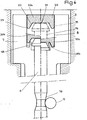
- FIG 1 we see the partitions 1 and 2 assembled in which is machined a hole 3 tapped on a part 3a of its length inside the partition 2. Inside the partition 1, the hole has a widening finished by a shoulder intended to receive the head of screw.
- the screw 5 has a threaded part 5a corresponding to the threaded part 3a of the hole inside the partition 2.
- the screw 5 is pierced with an axial bore 6 over its entire length and has a head 7 with a large diameter.
- the head 7 has an opening 8 of prismatic shape with a hexagonal section for the engagement of a screwing tool.
- Two radial direction holes 10 communicate with the central bore 6 of the screw at one of their ends and open at their other end onto the threaded external lateral surface 5a of the screw. Inside each of the holes 10 is arranged a ball 11, the diameter of which, as can be seen in FIG. 3a, is substantially equal to the maximum thickness of the tubular wall of the screw in its threaded part 5a.
- the rod 14 Inside the bore 6 of the screw is arranged a rod 14 engaged in this bore practically without play.
- the rod 14 comprises a head 15 whose diameter is substantially greater than the diameter of the bore 6 and a diameter part reduced 16 visible on the lower part of FIG. 4 on a larger scale, at its end opposite to the head 15.
- the reduced diameter part 16 is connected to the non reduced diameter part of the rod by a frustoconical surface.
- the reduced diameter part has a toroidal shape allowing it to come into contact with the balls 11, when the rod 14 is in its position shown in FIG. 1 or in the lower part of FIG. 4.
- the balls can come into the retracted position in the radial direction during the screwing of the screw 5 which causes the movement towards the inside of the balls 11 repelled by the threads of the tapped part 3a of the hole 3.
- the screw is put in place and screwed inside the tapped hole 3 by a tool whose external profile corresponds to the profile of the opening 8 of the screw head.
- the screw At the end of screwing, the screw is in its position shown in FIG. 2 where it ensures the closing of the gap between the partitions 1 and 2.
- This crimping tool 20 is designed so that it can be adapted on a device as described in French patent application No. 81 -14899 of July 30, 1981. As indicated, this tool has a prismatic external surface of a shape corresponding to the shape of the opening 8 of the screw head 7. Its lower part has a flat bearing surface 21, a bearing frustoconical 22 and a chamfer 23 making it easier to introduce it into the opening 8 of the screw head 7.
- the pressure on the balls is exerted by the frustoconical ramp located at the end of the reduced diameter zone.
- the radial advance of the balls towards the outside produces a crushing of the threads of the tapped part 3a of the hole 3, which causes a blocking in rotation and in translation of the screw.
- the tool 20 is then passed from position 20a to position 20b shown in FIG. 4. In its position 20b, the tool comes into contact through its frustoconical part 22 with the deformable parts 18 of the screw head 7.
- the deformable parts 18 are brought down until to bring them into a folded position 18b where they hold the head 15 of the operating rod against the bottom of the opening of the screw head.
- the fixing device is then in its blocking position shown in FIG. 3.
- the locking of the screw was obtained without deformation of this screw but simply by crushing the thread of the tapped hole in one of the partitions sounds on a very small surface corresponding to the contact surface with the ball.
- the balls are held in the locking position by the rod which is itself crimped on the screw.
- the means for blocking the screw can be different from spherical parts such as the balls 11 which have been described, these blocking means can be in the form of small cylinders whose end is rounded or any other suitable form. .
- the reduced diameter zone of the operating rod can have any shape facilitating the positioning of the operating rod in the locked position.
- the screw may have a single hole such as 10 which can receive a locking means, two holes arranged in opposite manner as in the embodiment which has been described, or three or more holes placed in angular positions regularly spaced around the axis of the screw.
- the fixing device according to the invention can be used outside the field of eliminating leakage spaces in the partitioning of a pressurized water nuclear reactor.
Abstract
L'invention concerne un dispositif et un procédé de fixation de deux pièces par vis imperdable. Le dispositif comporte une vis (5) engagée dans un trou taraudé (3) usiné dans l'une au moins des deux pièces (1, 2). La vis (5) comporte sour toute sa longueur un alésage (6) communiquant avec au moins un trou (10) de direction radiale débouchant sur la surface latérale externe de la vis (5) dans sa partie filetée (5a) et renfermant un élément (11) mobile dans le trou (10). Une tige de manoeuvre (14) est engagée dans l'alésage (6) pour le blocage de la vis (5) en place dans le trou taraudé (3), par mise en coïncidence d'une partie à plus grand diamètre de la tige avec l'élément (11) qui écrase alors le filetage de la partie (3a) du trou (3). La tige (14) est sertie sur la vis (5) grâce à des lamelles (18). L'invention s'applique, en particulier à l'assemblage de deux parois d'un cloisonnement du coeur d'un réacteur nucléaire à eau sous pression.The invention relates to a device and a method for fixing two parts by captive screw. The device comprises a screw (5) engaged in a tapped hole (3) machined in at least one of the two parts (1, 2). The screw (5) has, throughout its entire length, a bore (6) communicating with at least one hole (10) of radial direction opening onto the external lateral surface of the screw (5) in its threaded part (5a) and containing an element (11) movable in the hole (10). An operating rod (14) is engaged in the bore (6) for locking the screw (5) in place in the tapped hole (3), by coincidence of a larger diameter part of the rod with the element (11) which then crushes the thread of the part (3a) of the hole (3). The rod (14) is crimped onto the screw (5) by means of strips (18). The invention applies, in particular to the assembly of two walls of a partitioning of the core of a pressurized water nuclear reactor.
Description
L'invention concerne un dispositif de fixation de deux pièces par vis imperdable et le procédé de fixation correspondant.The invention relates to a device for fixing two parts by captive screw and the corresponding fixing method.
Dans les réacteurs nucléaires à eau sous pression, le coeur est constitué par un ensemble d'assemblages combustibles prismatiques disposés verticalement et côte à côte et généralement entourés par un cloisonnement périphérique qui épouse la forme extérieure du coeur. Ce cloisonnement permet en particulier de maintenir les assemblages du coeur et de canaliser l'eau sous pression vers la base du coeur, avant la traversée de celui-ci de bas en haut. Le cloisonnement du coeur d'un réacteur nucléaire à eau sous pression comprend généralement un ensemble de plaques verticales assemblées à angle droit et des dispositifs de maintien constitués par des plaques horizontales découpées suivant la forme de la section du coeur et intercalées entre l'ensemble des plaques verticales du cloisonnement et la virole de coeur.In pressurized water nuclear reactors, the core is constituted by a set of prismatic fuel assemblies arranged vertically and side by side and generally surrounded by a peripheral partitioning which matches the external shape of the core. This partitioning makes it possible in particular to maintain the assemblies of the core and to channel the water under pressure towards the base of the core, before crossing it from bottom to top. The partitioning of the core of a pressurized water nuclear reactor generally comprises a set of vertical plates assembled at right angles and holding devices constituted by horizontal plates cut according to the shape of the section of the core and interposed between all of the vertical plates of the partitioning and the ferrule of heart.
Entre les plaques verticales constituant la paroi du cloisonnement il peut apparaître, pendant--le fonctionnement du réacteur, des interstices si bien que l'eau sous pression peut passer sous forme de jets, de l'espace situé entre la virole de coeur et le cloisonnement dans le volume occupé par le coeur et limité par le cloisonnement. En effet, il existe une différence de pression de l'eau de refroidissement entre l'extérieur et l'intérieur du coeur, venant de la perte de charge à l'intérieur des assemblages constituant le coeur. Les jets sous pression dirigés depuis l'extérieur jusqu'à l'intérieur du coeur provoquent des vibrations des crayons des assemblages périphériques du coeur du réacteur, tout à fait dommageables pour la tenue en service de ces assemblages, les détériorations peuvent même aller jusqu'à une rupture de crayons combustibles.Between the vertical plates constituting the partition wall, there may appear, during the operation of the reactor, interstices so that the pressurized water can pass in the form of jets, from the space situated between the core shell and the partitioning in the volume occupied by the heart and limited by the partitioning. Indeed, there is a difference in pressure of the cooling water between the outside and the inside of the core, coming from the pressure drop inside the assemblies constituting the core. The pressurized jets directed from the outside to the inside of the core cause vibrations of the rods of the peripheral assemblies of the reactor core, quite damaging for the holding in service of these assemblies, the deteriorations can even go as far as rupture of fuel rods.
On a proposé dans la demande de brevet Français N°81-14899 de la société FRAMATOME et CIE un procédé et un dispositif pour éliminer les espaces de fuite entre les cloisons entourant le coeur d'un réacteur nucléaire à eau sous pression.In French patent application No. 81-14899 of the company FRAMATOME and CIE, a method and a device have been proposed for eliminating the leakage spaces between the partitions surrounding the core of a pressurized water nuclear reactor.
Ce procédé consiste à solidariser les cloisons deux à deux par un ensemble de vis traversantes et s'appuyant sur l'une des cloisons et vissées à l'intérieur d'un trou taraudé pratiqué dans l'autre cloison.This process consists in securing the partitions two by two by a set of through screws and based on one of the partitions and screwed inside a tapped hole made in the other partition.
Il est d'une grande importance que ces vis soient réalisées sous forme de vis imperdables qui ne soient pas susceptibles de se détacher sous l'effet des vibrations pendant le fonctionnement du réacteur et d'être entraînées par l'eau sous pression de refroidissement.It is of great importance that these screws are made in the form of captive screws which are not likely to come off under the effect of vibrations during the operation of the reactor and to be driven by water under cooling pressure.
On connait des dispositifs de freinage de vis par rondelles ou par clavetages mais ces dispositifs connus n'apportent pas une sécurité absolue et sont difficiles à mettre en oeuvre dans le cas d'une vis introduite à l'intérieur des cloisons du coeur d'un réacteur nucléaire.Screw braking devices are known by washers or keying but these known devices do not provide absolute security and are difficult to implement in the case of a screw inserted inside the partitions of the core of a nuclear reactor.
On connait également un dispositif de fixation à filets déformés décrit dans le brevet français N°1.478.075 où le déplacement d'une bille à l'intérieur d'un alésage prévu dans la vis permet la déformation de la partie filetée de cette vis dans une direction radiale. Cette déformation dis symétrique de la vis permet de réaliser un blocage en rotation de celle-ci à l'intérieur d'un trou taraudé dans laquelle elle est engagée. Cependant un tel dispositif n'apporte pas une sécurité absolue dans le cas des cloisons d'un réacteur nucléaire, puisqu'en cas de rupture de la vis, la partie de celle-ci comportant la tête peut se détacher de la cloison. Cette rupture peut-être provoquée par les sollicitations mécaniques ou thermiques dans le réacteur nucléaire ou par les conditions d'irradiation. Le fait de déformer le filetage de la vis peut en outre diminuer sa résistance mécanique.We also know a fixing device with deformed threads described in French patent N ° 1,478,075 where the displacement of a ball inside a bore provided in the screw allows the deformation of the threaded part of this screw in a radial direction. This dis symmetrical deformation of the screw makes it possible to block the latter in rotation inside a tapped hole in which it is engaged. However, such a device does not provide absolute security in the case of the partitions of a nuclear reactor, since in the event of the screw breaking, the part of the latter comprising the head can detach from the partition. This rupture may be caused by mechanical or thermal stresses in the nuclear reactor or by the irradiation conditions. Deforming the screw thread can further decrease its mechanical strength.
On a aussi proposé (US-A-3.390.712) un dispositif de blocage d'une vis par des éléments mobiles dans la direction radiale dans des logements traversant la partie filetée de la vis et communiquant avec un alésage central prévu sur toute la longueur de la vis. Une tige de blocage montée coulissante dans l'alésage central de la vis permet de déplacer les éléments mobiles pour les mettre en position de blocage lorsque la vis est en place dans un trou taraudé. Les éléments de blocage qui comportent des portions de filets d'un pas correspondant à celui du taraudage dans lequel est engagée la vis doivent être en coïncidence exacte avec les filets du taraudage pour venir en position de blocage par déplacement de la tige. Cette coîncidence exacte est difficile sinon impossible à réaliser dans le cas de vis de fixation de cloisons d'un réacteur nucléaire à eau sous pression. D'autre part, la tige de blocage n'est pas fixée sur la vis de façon à interdire toute possibilité de déplacement et donc de déblocage.A device has also been proposed (US-A-3,390,712) for locking a screw by elements movable in the radial direction in housings passing through the threaded part of the screw and communicating with a central bore provided over the entire length. of the screw. A locking rod slidingly mounted in the central bore of the screw makes it possible to move the mobile elements to put them in the locking position when the screw is in place in a tapped hole. The locking elements which comprise portions of threads with a pitch corresponding to that of the thread in which the screw is engaged must be in exact coincidence with the threads of the thread to come into the locking position by displacement of the rod. This exact coincidence is difficult if not impossible to achieve in the case of fixing screws for partitions of a pressurized water nuclear reactor. On the other hand, the locking rod is not fixed on the screw so as to prohibit any possibility of displacement and therefore of unlocking.
Le but de l'invention est donc de proposer un dispositif de fixation de deux pièces par vis imperdable comportant :
- - une vis engagée dans un trou taraudé sur une partie de sa longueur usiné dans l'une au moins des deux pièces, la vis présentant sur toute sa longueur et suivant son axe un alésage communiquant avec au moins un trou de direction radiale débouchant sur la surface latérale externe de la vis dans sa partie filetée,
- ,- et un ensemble de blocage de la vis dans le trou taraudé constitué par au moins un élément mobile dans le trou radial et une tige de manoeuvre engagée pratiquement sans jeu dans l'alésage comportant une tête et une partie à diamètre réduit à son extrémité disposée en face du trou renfermant le moyen de blocage lorsque la tige est dans une première position ou position hors service, le blocage de la vis étant réalisé par déplacement de la tige dans une seconde position ou position de blocage dans laquelle cette tige déplace le moyen de blocage radialement et vers l'extérieur, dispositif de fixation d'une très grande sûreté et facile à mettre en place sur le cloisonnement d'un réacteur nucléaire ayant fonctionné.
- - a screw engaged in a tapped hole over part of its length machined in at least one of the two parts, the screw having over its entire length and along its axis a bore communicating with at least one hole of radial direction opening on the external lateral surface of the screw in its threaded part,
- , - and a screw locking assembly in the tapped hole constituted by at least one movable element in the radial hole and an operating rod engaged practically without play in the bore comprising a head and a reduced diameter part at its end disposed opposite the hole containing the blocking means when the rod is in a first position or out of service position, the screw is blocked by displacement of the rod in a second position or blocking position in which this rod moves the means radially and outwardly locking, fastening device very safe and easy to install on the bulkhead of a nuclear reactor that has operated.
Dans ce but :
- - le moyen de blocage a une forme et une dimension radiale telles que ce moyen de blocage vient déformer par compression au moins un filet du trou taraudé lorsque la tige vient en position de service à l'intérieur de la vis introduite et vissée dans le trou taraudé,
- - et la vis comporte en outre des parties déformables au voisinage de la tête de la tige dans sa position de service pour le sertissage de cette tige en position de blocage sur la vis.
- - The locking means has a shape and a radial dimension such that this locking means deforms by compression at least one thread of the tapped hole when the rod comes into the service position inside the screw introduced and screwed into the hole tapped,
- - And the screw further comprises deformable parts in the vicinity of the head of the rod in its service position for crimping this rod in the locking position on the screw.
Afin de bien faire comprendre l'invention, on va maintenant décrire à titre d'exemple non limitatif, un mode de réalisation d'un dispositif de fixation suivant l'invention appliqué au cas d'une cloison du coeur d'un réacteur nucléaire à eau sous pression.
- La figure l représente une vue en coupe du dispositif de fixation au moment de son introduction dans le trou usiné dans les cloisons.
- La figure 2 est une vue en coupe du dispositif de fixation vissé à l'intérieur du trou taraudé des cloisons mais non bloqué.
- La figure 3 est une vue en coupe du dispositif de fixation dans sa position vissée et bloquée à l'intérieur du trou taraudé ménagé dans les cloisons.
- La figure 3a est une vue en coupe suivant AA de la figure 3.
- La figure 4 est une vue en coupe montrant les différentes positions d'un outil de vissage et de sertissage à l'intérieur de la tête d'une vis telle que représentée aux figures 1, 2 et 3, pendant le blocage du dispositif de fixation.
- Figure l shows a sectional view of the fixing device at the time of its introduction into the machined hole in the partitions.
- Figure 2 is a sectional view of the fixing device screwed inside the tapped hole of the partitions but not blocked.
- Figure 3 is a sectional view of the fixing device in its screwed and locked position inside the threaded hole formed in the partitions.
- FIG. 3a is a sectional view along AA of FIG. 3.
- Figure 4 is a sectional view showing the different positions of a screwing and crimping tool inside the head of a screw as shown in Figures 1, 2 and 3, during the locking of the fixing device .
Sur la figure 1, on voit les cloisons 1 et 2 assemblées dans lesquelles est usiné un trou 3 taraudé sur une partie 3a de sa longueur à l'intérieur de la cloison 2. A l'intérieur de la cloison 1, le trou comporte un élargissement terminé par un épaulement destiné à recevoir la tête de vis. La vis 5 comporte une partie filetée 5a correspondant à la partie taraudée 3a du trou à l'intérieur de la cloison 2. La vis 5 est percée d'un alésage axial 6 sur toute sa longueur et comporte une tête 7 à grand diamètre. La tête 7 comporte une ouverture 8 de forme prismatique à section hexagonale pour l'engagement d'un outil de vissage.In Figure 1, we see the
Deux trous de direction radiale 10 communiquent avec l'alésage central 6 de la vis à l'une de leurs extrémités et débouchent à leur autre extrémité sur la surface latérale externe filetée 5a de la vis. A l'intérieur de chacun des trous 10 est disposée une bille 11, dont le diamètre, ainsi qu'il est visible sur la figure 3a est sensiblement égal à l'épaisseur maximum de la paroi tubulaire de la vis dans sa partie filetée 5a.Two
Les bords des trous 10, à l'endroit où ces trous débouchent sur la surface latérale externe de la vis, sont légèrement rabattus vers l'intérieur pour retenir les billes 11 à l'intérieur des trous 10 correspondant.The edges of the
A l'intérieur de l'alésage 6 de la vis est disposée une tige 14 engagée dans cet alésage pratiquement sans jeu. La tige 14 comporte une tête 15 dont le diamètre est sensiblement supérieur au diamètre de l'alésage 6 et une partie à diamètre réduit 16 visible sur la partie inférieure de la figure 4 à plus grande échelle, à son extrémité opposée à la tête 15.Inside the bore 6 of the screw is arranged a
La partie à diamètre réduit 16 est reliée à la partie à diamètre non réduit de la tige par une surface tronconique. La partie à diamètre réduit a une forme torique permettant sa mise en contact avec les billes 11, lorsque la tige 14 est dans sa position représentée à la figure 1 ou dans la partie inférieur de la figure 4. Dans cette position hors service de la tige, les billes peuvent venir en position de retrait dans la direction radiale pendant le vissage de la vis 5 qui provoque le déplacement vers l'intérieur des billes 11 repoussées par les filets de la partie taraudée 3a du trou 3. A l'intérieur de l'ouverture 8 de la tête de vis 7, est prévue une collerette 18 usinée dans le métal de la vis et facilement déformable.The reduced
La vis est mise en place et vissée à l'intérieur du trou taraudé 3 par un outil dont le profil externe correspond au profil de l'ouverture 8 de la tête de vis.The screw is put in place and screwed inside the tapped
En fin de vissage, la vis est dans sa position représentée sur la figure 2 où elle assure la fermeture de l'interstice entre les cloisons 1 et 2.At the end of screwing, the screw is in its position shown in FIG. 2 where it ensures the closing of the gap between the
On réalise alors le blocage de la vis tel qu'il est représenté aux figures 3 et 3a en utilisant l'outil de vissage et de sertissage 20 représenté sur la figure 4. Cet outil de sertissage 20 est conçu de façon à pouvoir être adapté sur un dispositif tel que décrit dans la demande de brevet français N°81-14899 du 30 Juillet 1981. Comme indiqué, cet outil comporte une surface externe prismatique d'une forme correspondant à la forme de l'ouverture 8 de la tête vis 7. Sa partie inférieure comporte une surface d'appui plane 21, une portée tronconique 22 et un chanfrein 23 permettant de faciliter son introduction dans l'ouverture 8 de la tête de vis 7.The screw is then locked as shown in Figures 3 and 3a using the screwing and
En fin de vissage, la vis étant dans sa position représentée à la figure 2, on exerce une poussée axiale sur l'outil 20 grâce au dispositif décrit dans le brevet N°81-14899, de sorte que la.surface d'appui 21 vienne en contact avec la tête 15 de la tige de manoeuvre 14 et que cette tige soit poussée vers le fond du trou taraudé 3. Le mouvement de pénétration de la tige de manoeuvre amène une partie à diamètre non réduit de la tige en face des billes 11, si bien que celles-ci sont déplacées radialement vers l'extérieur comme représenté à la figure 3.At the end of screwing, the screw being in its position shown in FIG. 2, an axial thrust is exerted on the
Au cours de leur déplacement sous l'effort de poussée exercé sur la tige, la pression sur les billes est exercée par la rampe tronconique située à l'extrémité de la zone à diamètre réduit. L'avancée radiale des billes vers l'extérieur produit un écrasement des filets de la partie taraudée 3a du trou 3, ce qui provoque un blocage en rotation et en translation de la vis. L'outil 20 est-alors passé de la position 20a à la position 20b représentée sur la figure 4. Dans sa position 20b, l'outil vient en contact par sa partie tronconique 22 avec les parties déformables 18 de la tête de vis 7. En poursuivant le mouvement de l'outil 20 jusqu'au moment où la tête 15 de la tige de manoeuvre 14 vient en contact avec le fond de l'ouverture 8 de la tête de vis, on provoque le rabattement des parties déformables 18 jusqu'à les amener dans une position repliée 18b où elles maintiennent la tête 15 de la tige de manoeuvre contre le fond de l'ouverture de la tête de vis. Le dispositif de fixation est alors dans sa position de blocage représentée à la figure 3.During their movement under the pushing force exerted on the rod, the pressure on the balls is exerted by the frustoconical ramp located at the end of the reduced diameter zone. The radial advance of the balls towards the outside produces a crushing of the threads of the tapped
Dans cette position la vis est non seulement bloquée en rotation et en translation mais également fixée par rapport aux cloisons 1 et 2 de façon tout à fait sûre même en cas de rupture de la vis, puisque la tige 14 continue à maintenir la vis et évite qu'elle ne devienne un corps migrant dans l'eau de refroidissement du réacteur.In this position the screw is not only locked in rotation and in translation but also fixed relative to the
Le blocage de la vis a été obtenu sans déformation de cette vis mais simplement en écrasant le filetage du trou taraudé dans l'une des cloisons sur un très petite surface correspondant à la surface de contact avec la bille. Les billes sont maintenues en position de blocage par la tige qui est elle-même sertie sur la vis.The locking of the screw was obtained without deformation of this screw but simply by crushing the thread of the tapped hole in one of the partitions sounds on a very small surface corresponding to the contact surface with the ball. The balls are held in the locking position by the rod which is itself crimped on the screw.
Les opérations de mise en place et de blocage de la vis sont réalisées par simple vissage et par simple poussée sur une tige. Ces opérations peuvent être facilement réalisées avec l'outillage décrit dans la demande de brevet N°81-14899 du 30 Juillet 1981. En particulier, ces opérations seront réalisées sous eau depuis une position située au-dessus de la piscine du réacteur.The operations of placing and locking the screw are carried out by simple screwing and by simple pushing on a rod. These operations can be easily carried out with the tools described in patent application No. 81-14899 of July 30, 1981. In particular, these operations will be carried out under water from a position located above the reactor pool.
On doit bien comprendre que le mode de réalisation qui a été décrit n'est nullement limitatif et qu'il est possible de modifier des points de détail sans pour autant en sortir du cadre de l'invention.It should be understood that the embodiment which has been described is in no way limiting and that it is possible to modify points of detail without thereby departing from the scope of the invention.
C'est ainsi que les moyens de blocage de la vis peuvent être différents de pièces sphériques telles que les billes 11 qui ont été décrites, ces moyens de blocage peuvent avoir la forme de petits cylindres dont l'extrémité est arrondie ou tout autre forme convenable. La zone à diamètre réduit de la tige de manoeuvre peut avoir une forme quelconque facilitant la mise en place de la tige de manoeuvre en position de blocage.Thus the means for blocking the screw can be different from spherical parts such as the
La vis peut présenter un seul trou tel que 10 pouvant recevoir un moyen de blocage, deux trous disposés de façon opposés comme dans l'exemple de réalisation qui a été décrit, ou encore trois trous ou plus placés dans des positions angulaires régulièrement espacées autour de l'axe de la vis.The screw may have a single hole such as 10 which can receive a locking means, two holes arranged in opposite manner as in the embodiment which has been described, or three or more holes placed in angular positions regularly spaced around the axis of the screw.
Le dispositif de fixation suivant l'invention peut-être utilisé en dehors du domaine de l'élimination des espaces de fuite du cloisonnement d'un réacteur nucléaire à eau sous pression.The fixing device according to the invention can be used outside the field of eliminating leakage spaces in the partitioning of a pressurized water nuclear reactor.
Claims (6)
caractérisé par le fait que le moyen de blocage (11) a une forme et une dimension radiale telles que ce moyen de blocage vient déformer par compression au moins un filet du trou taraudé (3) lorsque la tige (14) vient en position de service à l'intérieur de la vis (5) introduite et vissée dans le trou taraudé (3),
et que la vis comporte en outre des parties déformables (18) au voisinage de la tête (15) de la tige (14) dans sa position de service pour le sertissage de cette tige en position de blocage sur la vis (5).1.- Device for fixing two parts (1, 2) by captive screw comprising:
characterized in that the locking means (11) has a shape and a radial dimension such that this locking means deforms by compression at least one thread of the tapped hole (3) when the rod (14) comes into the service position inside the screw (5) inserted and screwed into the tapped hole (3),
and that the screw also comprises deformable parts (18) in the vicinity of the head (15) of the rod (14) in its service position for crimping this rod in the locking position on the screw (5).
caractérisé par le fait que la vis comporte deux trous (10) situés dans le prolongement l'un de l'autre et dans des positions diamètralement opposées.3. A fixing device according to any one of claims 1 and 2,
characterized in that the screw has two holes (10) located in the extension of one another and in diametrically opposite positions.
caractérisé par le fait qu'on introduit la vis (5) dans le trou taraudé (3), qu'on réalise le vissage de cette vis (5) dans le trou taraudé (3), qu'on effectue alors une poussée sur la tige de manoeuvre (14) de façon à déplacer les moyens de blocage (11), dans la direction radiale et vers l'extérieur par mise en coïncidence de ces éléments (11) avec la zone à diamètre non réduit de la tige de manoeuvre (14) puis qu'on effectue le rabattement des parties déformables (18) de la tête de vis (7) sur la tête (15) de la tige de manoeuvre (14).5.- Method for fixing two parts by captive screw using the fixing device according to any one of claims 1 to 4,
characterized by the fact that the screw (5) is introduced into the threaded hole (3), that the screw (5) is screwed into the threaded hole (3), that a push is then made on the operating rod (14) so as to move the locking means (11), in the radial direction and towards the outside by making these elements (11) coincide with the non-reduced diameter zone of the operating rod ( 14) then that the deformable parts (18) of the screw head (7) are folded over the head (15) of the operating rod (14).
caractérisé par le fait que la mise en place et le blocage de la vis ont lieu sous eau, dans la piscine du réacteur nucléaire.6. A fixing method according to claim 5 in the case where the two parts (1 and 2) assembled by screws (5) are partitions of the core of a pressurized water nuclear reactor,
characterized by the fact that the setting and blocking of the screw takes place under water, in the nuclear reactor pool.
Applications Claiming Priority (2)
| Application Number | Priority Date | Filing Date | Title |
|---|---|---|---|
| FR8317279 | 1983-10-23 | ||
| FR8317279A FR2554185B1 (en) | 1983-10-28 | 1983-10-28 | DEVICE FOR FIXING TWO WORKPIECES BY IMPERSIBLE SCREW AND CORRESPONDING FIXING METHOD |
Publications (2)
| Publication Number | Publication Date |
|---|---|
| EP0148039A1 true EP0148039A1 (en) | 1985-07-10 |
| EP0148039B1 EP0148039B1 (en) | 1988-03-16 |
Family
ID=9293649
Family Applications (1)
| Application Number | Title | Priority Date | Filing Date |
|---|---|---|---|
| EP84402159A Expired EP0148039B1 (en) | 1983-10-28 | 1984-10-26 | Device to fix two parts by a non-losable bolt, and fixing process therefor |
Country Status (8)
| Country | Link |
|---|---|
| US (1) | US4681495A (en) |
| EP (1) | EP0148039B1 (en) |
| JP (1) | JPS60104810A (en) |
| KR (1) | KR850003771A (en) |
| CA (1) | CA1221477A (en) |
| DE (1) | DE3469943D1 (en) |
| ES (1) | ES296247Y (en) |
| FR (1) | FR2554185B1 (en) |
Cited By (1)
| Publication number | Priority date | Publication date | Assignee | Title |
|---|---|---|---|---|
| EP0647496A3 (en) * | 1991-11-15 | 1995-08-16 | Demmeler Maschinenbau | Studs. |
Families Citing this family (25)
| Publication number | Priority date | Publication date | Assignee | Title |
|---|---|---|---|---|
| US4850774A (en) * | 1987-10-26 | 1989-07-25 | The Boeing Company | Self-locking adjustable screw |
| US4843792A (en) * | 1988-06-27 | 1989-07-04 | Stageright Corporation | Socket support and interlock for staging panels |
| FR2721665B1 (en) * | 1994-06-22 | 1996-07-19 | Snecma | Lock nuts or screws and assemblies thus formed. |
| US5931621A (en) * | 1998-04-20 | 1999-08-03 | Lucent Technologies Inc | Locking mechanism for a rotatable fastener |
| DE19945295C1 (en) * | 1999-09-22 | 2001-01-25 | Jac Products Deutschland Gmbh | Support foot for automobile roof rail has pin section with threaded bore receiving bolt head of fixing bolt fitting through opening in automobile roof and secured by threaded nut |
| US6595714B2 (en) * | 2000-12-09 | 2003-07-22 | Tyee Aircraft | Swivel insert for a control rod |
| US6644903B1 (en) | 2001-06-12 | 2003-11-11 | Matdan America Corp. | Captive fastener with gradient hardened ferrule |
| US20060287166A1 (en) * | 2005-06-17 | 2006-12-21 | Alvarez Enrique L | Anchor system for use in an aquatic environment |
| US7458558B1 (en) | 2006-01-23 | 2008-12-02 | Patricia Toth | Controlled method and apparatus for releasing pressure |
| DE102006053141B3 (en) * | 2006-11-10 | 2008-06-19 | Atlas Copco Mai Gmbh | Improved slip anchor |
| EP2241230B1 (en) | 2007-12-12 | 2012-07-18 | Nestec S.A. | Used capsule or pod receptacle for liquid food or beverage machines |
| EP2070454B1 (en) | 2007-12-12 | 2015-07-15 | Nestec S.A. | Beverage production machines comprising a plurality of core units |
| MX2010009475A (en) * | 2008-02-29 | 2010-09-28 | Atlas Copco Mai Gmbh | Improved sliding anchor. |
| US8313066B2 (en) * | 2008-06-25 | 2012-11-20 | Medline Industries, Inc. | Intravenous fluid container stand and methods for making same |
| US20140352544A1 (en) | 2011-09-16 | 2014-12-04 | Alfred Yoakim | Clean multi-system beverage machine |
| BR112014005967A2 (en) | 2011-09-16 | 2017-04-04 | Nestec Sa | multi system beverage machine, multiple connections |
| BR112014005798A2 (en) | 2011-09-16 | 2017-03-28 | Nestec Sa | secure multi-system beverage machine connector |
| CN108691877A (en) * | 2017-04-10 | 2018-10-23 | 杨光明 | Self-locking fastener and its locking method |
| US10385909B2 (en) * | 2017-07-26 | 2019-08-20 | Core Bolt Co., Ltd. | Bolt structure having locking unit embedded therein |
| CN111132588A (en) | 2017-09-25 | 2020-05-08 | 雀巢产品有限公司 | Beverage machine with removable module |
| EP3687346A1 (en) | 2017-09-25 | 2020-08-05 | Société des Produits Nestlé S.A. | Beverage machines with modularity |
| CN109519463B (en) * | 2018-11-14 | 2020-08-28 | 苏州剑派实业有限公司 | Self-locking bolt |
| RU2020103575A (en) | 2020-01-28 | 2021-07-28 | Зе Боинг Компани | ADJUSTABLE CONNECTING ROD ASSEMBLIES WITH JOINT END AND APPROPRIATE METHODS |
| CN113374772A (en) * | 2021-05-26 | 2021-09-10 | 张鹏辉 | High-strength screw fastener |
| US20230055414A1 (en) * | 2021-08-17 | 2023-02-23 | Richard Sukhdeo | Connector for removable tailgate |
Citations (5)
| Publication number | Priority date | Publication date | Assignee | Title |
|---|---|---|---|---|
| US2800247A (en) * | 1951-10-17 | 1957-07-23 | Arthur I Appleton | Closure member |
| FR1283372A (en) * | 1961-01-02 | 1962-02-02 | Vickers Armstrongs Aircraft | Improvement in pin assemblies |
| FR1478075A (en) * | 1965-04-29 | 1967-04-21 | Deutsch Fastener Corp | Deformed thread fastener to resist vibrations |
| US3390712A (en) * | 1966-12-22 | 1968-07-02 | Whittaker Corp | Self-locking fastener |
| EP0071536A1 (en) * | 1981-07-30 | 1983-02-09 | Framatome | Device for eliminating the leaks through the partitions surrounding the core of a P.W.R. |
Family Cites Families (5)
| Publication number | Priority date | Publication date | Assignee | Title |
|---|---|---|---|---|
| FR736064A (en) * | 1932-04-28 | 1932-11-18 | Lemer Fils Et V Brisson L | Device to prevent fraudulent unscrewing of screws |
| US3180390A (en) * | 1962-03-14 | 1965-04-27 | Jr Edward H Ockert | Securing device |
| SU456096A1 (en) * | 1973-06-18 | 1975-01-05 | Предприятие П/Я А-3214 | Screw |
| DE3007650C2 (en) * | 1980-02-29 | 1982-04-01 | Artur Dr.H.C. 7244 Waldachtal Fischer | Expansion dowel for anchoring in drilled holes made conically widened inwards |
| US4507034A (en) * | 1982-10-01 | 1985-03-26 | Adjustable Bushing Corporation | Expandable bushing and lock fastener |
-
1983
- 1983-10-28 FR FR8317279A patent/FR2554185B1/en not_active Expired
-
1984
- 1984-10-15 CA CA000465425A patent/CA1221477A/en not_active Expired
- 1984-10-19 JP JP59220344A patent/JPS60104810A/en active Pending
- 1984-10-24 KR KR1019840006605A patent/KR850003771A/en not_active Application Discontinuation
- 1984-10-26 EP EP84402159A patent/EP0148039B1/en not_active Expired
- 1984-10-26 DE DE8484402159T patent/DE3469943D1/en not_active Expired
- 1984-10-26 ES ES1984296247U patent/ES296247Y/en not_active Expired
- 1984-10-29 US US06/666,022 patent/US4681495A/en not_active Expired - Fee Related
Patent Citations (5)
| Publication number | Priority date | Publication date | Assignee | Title |
|---|---|---|---|---|
| US2800247A (en) * | 1951-10-17 | 1957-07-23 | Arthur I Appleton | Closure member |
| FR1283372A (en) * | 1961-01-02 | 1962-02-02 | Vickers Armstrongs Aircraft | Improvement in pin assemblies |
| FR1478075A (en) * | 1965-04-29 | 1967-04-21 | Deutsch Fastener Corp | Deformed thread fastener to resist vibrations |
| US3390712A (en) * | 1966-12-22 | 1968-07-02 | Whittaker Corp | Self-locking fastener |
| EP0071536A1 (en) * | 1981-07-30 | 1983-02-09 | Framatome | Device for eliminating the leaks through the partitions surrounding the core of a P.W.R. |
Cited By (1)
| Publication number | Priority date | Publication date | Assignee | Title |
|---|---|---|---|---|
| EP0647496A3 (en) * | 1991-11-15 | 1995-08-16 | Demmeler Maschinenbau | Studs. |
Also Published As
| Publication number | Publication date |
|---|---|
| ES296247U (en) | 1987-08-16 |
| FR2554185B1 (en) | 1987-04-10 |
| ES296247Y (en) | 1988-03-16 |
| CA1221477A (en) | 1987-05-05 |
| KR850003771A (en) | 1985-06-26 |
| EP0148039B1 (en) | 1988-03-16 |
| DE3469943D1 (en) | 1988-04-21 |
| JPS60104810A (en) | 1985-06-10 |
| FR2554185A1 (en) | 1985-05-03 |
| US4681495A (en) | 1987-07-21 |
Similar Documents
| Publication | Publication Date | Title |
|---|---|---|
| EP0148039B1 (en) | Device to fix two parts by a non-losable bolt, and fixing process therefor | |
| EP0007251B1 (en) | Nuclear fuel unit that can be assembled and dismantled from a distance, and tools therefor | |
| FR2706088A1 (en) | Connector for coaxial cables with corrugated tube. | |
| CA2060841A1 (en) | Device for temporary support of a lifting component on a metal planking during the pouring and setting phases of prefabricated concrete | |
| FR2497899A1 (en) | CONNECTABLE CONNECTION DEVICE FOR GUIDE LINE | |
| EP3589445B1 (en) | Quick-clamping spindle | |
| FR2652673A2 (en) | DEVICE FOR SEALING AND RETAINING A SEALING CAP OF A STEAM GENERATOR TUBE. | |
| EP0219412B1 (en) | Device for locking a guide ring onto a plate comprising a hole and its use in a guide tube of a nuclear reactor | |
| EP0026141A1 (en) | Screwed security assembly | |
| EP0071536A1 (en) | Device for eliminating the leaks through the partitions surrounding the core of a P.W.R. | |
| BE1006028A3 (en) | DEVICE AND METHOD unscrewing REMOTE AND EXTRACTION OF SCREW. | |
| FR2689297A1 (en) | Cutting tube lining sleeves which penetrate nuclear reactor vessel cover - to enable repair of welds between sleeves and cover and replace the cut tubes | |
| EP0428433B1 (en) | Device for fixation of upper spider guide plate in a nuclear reactor vessel | |
| EP1882794A1 (en) | Device for assembling vertical edges of form panels | |
| EP0238767A1 (en) | Assembly of a removable and lockable guide ring with a plate and its application to a guide tube of a nuclear reactor | |
| FR2732153A1 (en) | DEVICE FOR ASSEMBLING TWO PLATES OF THE PARTITION OF THE HEART OF A NUCLEAR REACTOR | |
| EP0019544B1 (en) | Transport container closure device for an assemblage irradiated in a nuclear reactor | |
| FR2718276A1 (en) | Sealing device for an instrumentation column. | |
| FR2673032A1 (en) | Method and device for replacing a centring pin (spindle) of a fuel assembly fixed on the upper core plate of a pressurised water nuclear reactor | |
| FR2717943A1 (en) | Replacing nuclear fuel centering pin and replacement pins | |
| EP0349379A1 (en) | Control spider with removable rods for a nuclear fuel assembly | |
| BE1008091A6 (en) | Sealing device for an instrumentation column passing through the lid of anuclear reactor tank | |
| EP0232633A1 (en) | Device for securing a connecting socket to the end of a cable | |
| FR2705822A1 (en) | Device for centring and aligning a fuel assembly under an upper core plate of a pressurised water nuclear reactor and method for replacing a centring pin | |
| BE1012055A3 (en) | Device for fixing nut. |
Legal Events
| Date | Code | Title | Description |
|---|---|---|---|
| PUAI | Public reference made under article 153(3) epc to a published international application that has entered the european phase |
Free format text: ORIGINAL CODE: 0009012 |
|
| AK | Designated contracting states |
Designated state(s): BE DE GB SE |
|
| 17P | Request for examination filed |
Effective date: 19850926 |
|
| 17Q | First examination report despatched |
Effective date: 19860526 |
|
| GRAA | (expected) grant |
Free format text: ORIGINAL CODE: 0009210 |
|
| AK | Designated contracting states |
Kind code of ref document: B1 Designated state(s): BE DE GB SE |
|
| GBT | Gb: translation of ep patent filed (gb section 77(6)(a)/1977) | ||
| REF | Corresponds to: |
Ref document number: 3469943 Country of ref document: DE Date of ref document: 19880421 |
|
| PLBE | No opposition filed within time limit |
Free format text: ORIGINAL CODE: 0009261 |
|
| STAA | Information on the status of an ep patent application or granted ep patent |
Free format text: STATUS: NO OPPOSITION FILED WITHIN TIME LIMIT |
|
| 26N | No opposition filed | ||
| PGFP | Annual fee paid to national office [announced via postgrant information from national office to epo] |
Ref country code: DE Payment date: 19921002 Year of fee payment: 9 |
|
| PGFP | Annual fee paid to national office [announced via postgrant information from national office to epo] |
Ref country code: GB Payment date: 19921020 Year of fee payment: 9 |
|
| PGFP | Annual fee paid to national office [announced via postgrant information from national office to epo] |
Ref country code: SE Payment date: 19921028 Year of fee payment: 9 Ref country code: BE Payment date: 19921028 Year of fee payment: 9 |
|
| PG25 | Lapsed in a contracting state [announced via postgrant information from national office to epo] |
Ref country code: GB Effective date: 19931026 |
|
| PG25 | Lapsed in a contracting state [announced via postgrant information from national office to epo] |
Ref country code: SE Effective date: 19931027 |
|
| PG25 | Lapsed in a contracting state [announced via postgrant information from national office to epo] |
Ref country code: BE Effective date: 19931031 |
|
| BERE | Be: lapsed |
Owner name: FRAMATOME ET CIE Effective date: 19931031 |
|
| GBPC | Gb: european patent ceased through non-payment of renewal fee |
Effective date: 19931026 |
|
| PG25 | Lapsed in a contracting state [announced via postgrant information from national office to epo] |
Ref country code: DE Effective date: 19940701 |
|
| EUG | Se: european patent has lapsed |
Ref document number: 84402159.2 Effective date: 19940510 |