EP0147872A2 - Procédé et installation pour la fabrication d'objets en matière composite - Google Patents
Procédé et installation pour la fabrication d'objets en matière composite Download PDFInfo
- Publication number
- EP0147872A2 EP0147872A2 EP84200699A EP84200699A EP0147872A2 EP 0147872 A2 EP0147872 A2 EP 0147872A2 EP 84200699 A EP84200699 A EP 84200699A EP 84200699 A EP84200699 A EP 84200699A EP 0147872 A2 EP0147872 A2 EP 0147872A2
- Authority
- EP
- European Patent Office
- Prior art keywords
- mandrel
- bag
- ply
- surface portion
- seal
- Prior art date
- Legal status (The legal status is an assumption and is not a legal conclusion. Google has not performed a legal analysis and makes no representation as to the accuracy of the status listed.)
- Granted
Links
Images


Classifications
-
- B—PERFORMING OPERATIONS; TRANSPORTING
- B29—WORKING OF PLASTICS; WORKING OF SUBSTANCES IN A PLASTIC STATE IN GENERAL
- B29C—SHAPING OR JOINING OF PLASTICS; SHAPING OF MATERIAL IN A PLASTIC STATE, NOT OTHERWISE PROVIDED FOR; AFTER-TREATMENT OF THE SHAPED PRODUCTS, e.g. REPAIRING
- B29C70/00—Shaping composites, i.e. plastics material comprising reinforcements, fillers or preformed parts, e.g. inserts
- B29C70/04—Shaping composites, i.e. plastics material comprising reinforcements, fillers or preformed parts, e.g. inserts comprising reinforcements only, e.g. self-reinforcing plastics
- B29C70/28—Shaping operations therefor
- B29C70/30—Shaping by lay-up, i.e. applying fibres, tape or broadsheet on a mould, former or core; Shaping by spray-up, i.e. spraying of fibres on a mould, former or core
- B29C70/34—Shaping by lay-up, i.e. applying fibres, tape or broadsheet on a mould, former or core; Shaping by spray-up, i.e. spraying of fibres on a mould, former or core and shaping or impregnating by compression, i.e. combined with compressing after the lay-up operation
- B29C70/342—Shaping by lay-up, i.e. applying fibres, tape or broadsheet on a mould, former or core; Shaping by spray-up, i.e. spraying of fibres on a mould, former or core and shaping or impregnating by compression, i.e. combined with compressing after the lay-up operation using isostatic pressure
-
- B—PERFORMING OPERATIONS; TRANSPORTING
- B29—WORKING OF PLASTICS; WORKING OF SUBSTANCES IN A PLASTIC STATE IN GENERAL
- B29C—SHAPING OR JOINING OF PLASTICS; SHAPING OF MATERIAL IN A PLASTIC STATE, NOT OTHERWISE PROVIDED FOR; AFTER-TREATMENT OF THE SHAPED PRODUCTS, e.g. REPAIRING
- B29C70/00—Shaping composites, i.e. plastics material comprising reinforcements, fillers or preformed parts, e.g. inserts
- B29C70/04—Shaping composites, i.e. plastics material comprising reinforcements, fillers or preformed parts, e.g. inserts comprising reinforcements only, e.g. self-reinforcing plastics
- B29C70/28—Shaping operations therefor
- B29C70/54—Component parts, details or accessories; Auxiliary operations, e.g. feeding or storage of prepregs or SMC after impregnation or during ageing
- B29C70/541—Positioning reinforcements in a mould, e.g. using clamping means for the reinforcement
-
- B—PERFORMING OPERATIONS; TRANSPORTING
- B29—WORKING OF PLASTICS; WORKING OF SUBSTANCES IN A PLASTIC STATE IN GENERAL
- B29C—SHAPING OR JOINING OF PLASTICS; SHAPING OF MATERIAL IN A PLASTIC STATE, NOT OTHERWISE PROVIDED FOR; AFTER-TREATMENT OF THE SHAPED PRODUCTS, e.g. REPAIRING
- B29C43/00—Compression moulding, i.e. applying external pressure to flow the moulding material; Apparatus therefor
- B29C43/02—Compression moulding, i.e. applying external pressure to flow the moulding material; Apparatus therefor of articles of definite length, i.e. discrete articles
- B29C43/10—Isostatic pressing, i.e. using non-rigid pressure-exerting members against rigid parts or dies
- B29C43/12—Isostatic pressing, i.e. using non-rigid pressure-exerting members against rigid parts or dies using bags surrounding the moulding material or using membranes contacting the moulding material
-
- Y—GENERAL TAGGING OF NEW TECHNOLOGICAL DEVELOPMENTS; GENERAL TAGGING OF CROSS-SECTIONAL TECHNOLOGIES SPANNING OVER SEVERAL SECTIONS OF THE IPC; TECHNICAL SUBJECTS COVERED BY FORMER USPC CROSS-REFERENCE ART COLLECTIONS [XRACs] AND DIGESTS
- Y10—TECHNICAL SUBJECTS COVERED BY FORMER USPC
- Y10T—TECHNICAL SUBJECTS COVERED BY FORMER US CLASSIFICATION
- Y10T156/00—Adhesive bonding and miscellaneous chemical manufacture
- Y10T156/10—Methods of surface bonding and/or assembly therefor
- Y10T156/1002—Methods of surface bonding and/or assembly therefor with permanent bending or reshaping or surface deformation of self sustaining lamina
- Y10T156/1043—Subsequent to assembly
- Y10T156/1044—Subsequent to assembly of parallel stacked sheets only
Definitions
- This invention relates to methods and apparatus for forming and compacting composite material articles and, more particularly, to such a method and apparatus which are mechanized and in which each ply of a fiber reinforced composite material is formed and compacted. on a mandrel before laying the next ply on the mandrel.
- One type of aircraft structure that may be fabricated from a composite material is a frame member, such as a stringer, that is channeled to form a generally U-shaped cross section.
- Such frame members may be fabricated by laying a series of plies of prepreg tape over a lay-up mandrel. The plies of the prepreg tape are laid one at a time and must be formed and compacted against the lay-up mandrel prior to the application of any additional plies.
- the flat tape that is to form the ply must be bent and formed to conform to the contour of the lay-up mandrel prior to the compaction of the ply.
- the compaction of each ply serves to remove all the entrapped air between the mandrel and the ply in order to produce a void free lay-up. Therefore, the compaction of each ply must be performed before the addition of the next ply.
- the conventional technique for compacting or debulking each ply is a manual procedure in which the article being fabricated is bagged with an airtight plastic film. This film is placed over the mandrel manually, and its edges are manually sealed with a vacuum sealant. A vacuum is then applied between the ply being compacted and the plastic film. Atmospheric pressure against the outside of the plastic film provides the compaction force while the vacuum removes the entrapped air.
- This procedure has the serious disadvantages of being very time consuming and of requiring considerable operator skill when contoured parts, such as channel stringers, are being compacted. The operator must not only ensure that a good edge seal has. been obtained, but also must ensure that there are no large wrinkles or bridging in the plastic film. "Bridging" indicates an area where the film does not contact the lay-up mandrel or the ply being compacted. Wrinkles and bridging result in areas of the ply which are not reliably compacted.
- the patent literature includes a number of examples of methods and apparatus for forming a single layer or multiple layers of material over a mold surface.
- the following United States patents each disclose a method and/or apparatus in which sheet material and a mold surface are placed in a chamber which is pressurized to force a membrane or diaphragm over the mold surface to in turn form the sheet material to the contour or shape of the mold surface: No. 2,342,988, granted February 29, 1944, to E. L. Vidal; No. 2,385,083, granted September 18, 1945, to D. C. Kemerer; No. 2,401,299, granted June 4, 1946, to R. E. Glavin; No. 3,546,740, granted December 15, 197a, to H. G. Johnson; No.
- Kemerer patent and the two Johnson patents disclose procedures in which a single sheet of material, such as a metal sheet, is formed.
- Each of the other patents discloses a process in which a plurality of layers are formed against a mold surface during a single forming process.
- Duggins et al disclose an alternative process in which a plunger is urged against a membrane to form the membrane into the desired shape and urge it against the work material which is in turn urged against a mold surface.
- the plunger is perforated to provide openings for a vacuum that serves to control the shape of the membrane so that it conforms to the shape of the plunger.
- a vacuum that serves to control the shape of the membrane so that it conforms to the shape of the plunger.
- a mold box and three sheets of material to be formed together form a chamber.
- a mold having a number of perforations is placed inside the chamber.
- the chamber is evacuated to draw the three sheets of material onto the mold surface to form the sheets into a laminated chair.
- the use of a vacuum in the device disclosed by Johnson 3,546,740 is described above.
- U.S. Patent No. 2,510,215, granted June 6, 1950, to A, F. Pityo et al discloses a process in which a yieldable plunger forces a circular blank of material against a female die during the manufacture of a globe hemisphere.
- U.S. Patent No. 3,576,930, granted April 27, 1971, to L. H. Watters et al a process of preparing molded articles is described in which the article is formed on a flexible mold member which is forced down into a rigid bowl-like support member. At the end of the process, a fluid pressure is applied between the rigid support member and the flexible mold member to move the flexible mold member away from the support member preceeding the removal of the molded article from the flexible mold member.
- Patent No. 4,301,099, granted November 17, 1981, to E. Broeksema et al discloses a method and device for manufacturing a plastic record carrier.
- a flexible substrate is pressed against a mold with ⁇ a liquid resin between the substrate and the mold.
- the resin spreads out, and the finished product has two layers of a substrate and the resin.
- a subject of the invention is apparatus for forming a composite material article having a desired shape.
- the apparatus comprises a mandrel having a vacuum ported upper surface portion that conforms to the desired shape of the article.
- a seal is carried by the mandrel and surrounds the perimeter of the upper surface portion of the mandrel.
- the apparatus also includes a flexible bag and inflating means for inflating the bag into a stretched condition.
- Lowering means is provided for lowering the bag in such stretched condition over the upper surface portion of the mandrel and into sealing engagement with the seal, to form a ply of fiber reinforced composite material that has been laid on such upper surface portion to the shape of the upper surface portion, and for raising the bag out of contact with the mandrel.
- Vacuum means evacuates, through said upper surface portion of the mandrel, the area between the bag and the mandrel and within the seal, to compact said ply.
- said upper surface portion of the mandrel is contoured.
- the contoured upper surface portion may include an elongated contoured bend line.
- the upper surface portion of the mandrel is generally U-shaped in cross section, with a top generally horizontal web and two side generally vertically flanges.
- the seal is generally saddle-shaped.
- Another subject of the invention is a method of forming a composite material article.
- the method comprises laying a ply of fiber reinforced composite material onto a vacuum ported mandrel having a shape conforming to the desired shape of the article.
- a flexible bag is inflated into a stretched condition.
- the inflated bag is lowered over the mandrel to form the ply to the shape of the mandrel, and a portion of the bag is brought into sealing engagement with a seal carried by the mandrel around the perimeter of the ply.
- a vacuum is applied through the mandrel to the area between the bag and the mandrel and within the seal to compact the ply.
- the bag is raised to take it out of contact with the mandrel and the ply. Additional plies of fiber reinforced composite material are laid as necessary to obtain a desired thickness. Each such additional ply is formed and compacted before laying another ply.
- the step of lowering the bag to form the ply includes allowing portions of the bag to unstretch to prevent formation of wrinkles, and allowing other portions of the bag to stretch further to prevent bridging. Also preferably, such step includes allowing the bag to roll over essentially the entire length of an elongated contoured bend line on the mandrel essentially simultaneously, to fold the ply along the bend line and at the same time restrain the ply from folding along a straight line.
- the method and apparatus of the invention provide improved means for forming and compacting composite material articles that avoids the problems discussed above in connection with conventional fabrication techniques. Since all the layers of the article may be laid, formed, and compacted on a single mandrel and since the forming and compacting procedures are mechanized, the ⁇ forming of the article using the method and apparatus of the invention may be carried out relatively quickly and with a minimal amount of skill of the operator. The savings in time and the absence of a need for skilled labor results in considerable savings in the cost of the operation.
- the mechanization of the method and the apparatus of the invention also avoids the problems of wrinkling, bridging, and difficulty in forming bend lines discussed above. These problems are avoided without the intervention of expensive skilled labor.
- the bag As the bag is lowered over the mandrel and the mandrel penetrates the bag, the bag rolls over the mandrel surface and the ply of composite material, forming the ply as it moves.
- the bag rolls over contours there are certain areas where there is excessive bag material.
- the inflating of the bag into a stretched condition before lowering it prevents wrinkles from appearing in such areas since the excess bag material in such areas is taken up by the bag unstretching in such areas.
- the flexible bag In areas where bridging might otherwise occur, the flexible bag is stretched by the inflating fluid therein to prevent bridging and provide contact in the area subject to bridging.
- the fluid pressure in the inflated bag also holds the bag against the seal to provide an automatic and reliable seal.
- the rolling action of the bag over the mandrel results in essentially the entire length of . any contoured bend lines being formed at essentially the same time.
- the bag restrains the ply of material from folding in a straight line, and the bend line is controlled to follow the contour of the mandrel. It is not possible to achieve such simultaneous folding or bending and restraining action by a hand forming operation.
- the method and apparatus of the invention provide a relatively quick and inexpensive means for reliably and accurately forming a composite material article.
- the method and apparatus are applicable to a wide variety of composite material shapes, including elongated channel members having contoured bend lines.
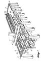
- FIG. 9 show apparatus that is constructed according to the invention and that also constitutes the best mode of the apparatus of the invention currently known to the applicant.
- the forming process and the apparatus illustrated in the drawings is designed for use in the forming of elongated channel stringers such as that shown in Fig. 9. It is anticipated that one of the primary uses of the method and apparatus of the invention will be to form and compact such elongated contoured members. However, it is of course to be understood that the method and apparatus of the invention may also be used to great advantage in the fabrication of composite material articles of other shapes and sizes.
- the structure shown includes a number of features that are well-known in the art.
- the structure includes two side rails 2, 4 along and between which a gantry 6 moves horizontally.
- a tape laying head 8 is carried by the gantry 6 and is movable along the gantry 6 in a horizontal direction perpendicular to the side rails 2, 4. This type of arrangement is known in the art and permits the accurate positioning of the tape laying head at the beginning of a tape course.
- the tape laying head 8 carries a roller 10 which presses on a piece of tape to urge the tape against the mandrel 30 and lay the tape on the mandrel 30.
- the structure shown in Fig. 1 also includes two side ply dispensing heads 12.
- These heads 12 are used for dispensing plies of tape that cover the flange portions of the finished article but not the web portion. These side plies are subsequently hand applied along the generally vertical surfaces of the mandrel 30. Such side plies of tape are illustrated in Fig. 8 and designated by the reference numeral 104.
- the apparatus of the invention includes,a mandrel that has an upper surface portion that conforms :,to the desired shape of the article to be formed.
- this upper surface of the mandrel 30 has a generally U-shaped cross section and includes a generally horizontal top web 32 and two essentially vertical side flanges 34, 36 extending downwardly from the side edges of the top web 32. These side flanges 34, 36 remain essentially vertical along the entire length of the mandrel 30.
- a bend line is defined along each top side edge of the mandrel 30 where the top web 32 meets one of the flanges 34, 36.
- Each of these bend lines is contoured to follow the desired contour of the finished elongated frame member or channel stringer to be formed on the mandrel 30.
- the orientation of the top web 32 is generally horizontal but varies from the horizontal along the length of the mandrel 30 because of the contouring of the bend lines.
- the shape of the mandrel 30 is most clearly illustrated in Figs. 9 and 9A-9C. These figures illustrate the shape of the finished frame member 60 formed on the mandrel 30.
- the frame member 60 has an inner channel surface that matches the upper surface of the mandrel 30.
- the frame member or channel stringer 60 has a top web 62 and side flanges 64, 66 that correspond to the web 32 and flanges 34, 36 of the mandrel 30.
- the web 62 meets the flanges 64, 66 along elongated contoured bend lines 68, 70, respectively.
- the apparatus of the invention also includes a flexible bag that may be inflated into a stretched condition and means for raising and lowering the bag over the mandrel.
- the bag 20 has an elongated generally oblong shape.
- the bag 20 has a rigid top piece 24 which provides support for the bag 20 and maintains the elongated shape of the bag 20.
- the bag 20 is preferably provided with a support framework 22 that is attached to the top piece 24 of the bag 20 and that is engaged by the means 'for raising and lowering the bag 20.
- the means for raising and lowering the bag may take any of a variety of forms.
- two ball screw drives 26 are shown that engage the support framework 22. These drives 26 are operated to raise and lower the framework 22 and bag 20 as needed.
- Mandrels constructed according to the invention carry a seal that surrounds the perimeter of the upper surface portion of the mandrel and that is engaged by the inflatable bag.
- the seal 38 carried by the mandrel 30 has an elongated saddle shape and forms a continuous loop that runs across the top web 32 of the mandrel 30 at each end of the mandrel 30 and runs along the lower sides of the side flanges 34, 36 of the mandrel 30.
- the seal 38 is preferably attached to the mandrel by a silicone adhesive.
- An example of a suitable material for the seal 38 is silicone rubber.
- the apparatus of the invention is also provided with means for evacuating the space between the inflatable bag and the mandrel.
- the upper surface portion of - the mandrel 30 is vacuum ported, with a number of vacuum ports 42 opening onto the upper surface portion within the seal 38.
- the evacuating means also includes a vacuum line 40 that extends through a lower portion of the mandrel 30 to communicate with the ports 42 via passageways 44.
- the vacuum line 40 extends laterally outwardly from the mandrel 30 and is hooked up to a vacuum device (not shown) to provide a vacuum through the upper surface portion of the mandrel 30.
- the bag 20 may be made from a number of materials.
- One such material is silicone rubber.
- the bag 20 has a piece 46 of direct contact breather material bonded thereon.
- This material 46 is positioned and dimensioned to be within the seal 38 and cover the upper surface portion of the mandrel 30, including vacuum ports 42, when the bag 20 is fully lowered. (See Fig. 7)
- the material 46 contacts patches 48 of porous material bonded on the surface of the mandrel 30 over the openings of ports 42. Together, the material 46 and the patches 48 provide an air path for the evacuation process described above.
- the material 46 may be, for example, a silicone rubber impregnated woven material.
- the patches 48 may be made from, for example, a woven fiberglass cloth.
- Figs. 2 and 3 show a ply 100 of fiber reinforced composite material being laid on the mandrel 30.
- the illustrated tape laying process shows the prepreg tape or ply 100 of material being laid at an angle of 0° to the longitudinal axis of the mandrel 30 and the finished longitudinal member. It is course to be understood that the ply of composite material may be laid in other orientations to attain the desired structural characteristics of the finished longitudinal member.
- Figs. 2 and 3 show the ply of tape 100 being laid along the mandrel 30 by_the roller 10 of the tape laying head 8. As can be clearly seen in Fig. 3, the web portion of the ply 100 is urged against the top web 32 of the mandrel 30 and the flange portions of the ply are laid in a cantilevered fashion.
- Figs. 4 and 5 illustrate the bag 20 being lowered down over the mandrel 30 to form the side flange portions of the ply 100 against the side flanges 34, 36 of the mandrel 30.
- a blower 28 Before the bag 20 is lowered, it is inflated by the use of a blower 28. The inflation of the bag 20 is carried out until the bag 20 is in a stretched condition. This stretching of the bag 20 prevents the formation of wrinkles and bridging and provides smooth contoured bend lines, as described above.
- the amount of stretch of the bag 20 can be varied by selection of both the blower and the bag material thickness.
- the internal air pressure in the bag 20 from the blower 28 forces the bag 20 against the upper surface of the mandrel 30.
- the bag 20 rolls along the surface of the mandrel 30 and a lower portion of the bag 20 is forced by such internal air pressure against the saddle-shaped seal 38.
- the bag 20 sealingly engages the seal 38 to seal the area between the upper surface of the mandrel 30 and the bag 20 which is described by the seal 38.
- Figs. 4 and 5 show the bag 20 just completing its sealing engagement with the seal 38.
- the area between the mandrel 30 and the bag 20 is evacuated by a vacuum acting through the vacuum line 40 and the ports 42 in the mandrel 30. This area is tightly sealed by the engagement of the bag 20 with the seal 38. The evacuation of this area serves to remove all the entrapped air between the bag 20 and the upper surface of the mandrel 30 and to bring the bag 20 into tighter engagement with the mandrel 30. This compacts the ply 100 of composite material and produces a void free lay-up of the material.
- Figs. 6 and 7 illustrate the evacuation process near its completion.
- the bag 20 is raised up out of contact with the ply 100 and mandrel 30.
- the bag 20 and its support framework 22 are then moved laterally away from the mandrel 30 along end rails 5, and either the tape laying head 8 is brought into engagement with the mandrel 30 to lay the next ply of composite material or the side ply dispensing heads 12 are used to dispense the next side plies for application.
- the method and apparatus of the invention allow for the easy and quick removal of the bag 20 between forming and compacting operations to in turn allow for the automated laying of additional plies of material. As many additional plies of material are laid as necessary to obtain the desired thickness of the finished article.
- each of these layers or plies is formed and compacted before laying the next ply.
- the formed article is cured.
- the forming of the article on the mandrel as the plies are being laid has the advantage of providing an article with finished dimensions to thus avoid assembly difficulties while preparing for curing.
- Fig. 8 illustrates a typical lay-up pattern for forming a channel stringer.
- the plies that cover both the side flanges 34, 36 and the top web 32 of the mandrel 30 are oriented at angles of plus and minus 45° to the longitudinal axis of the stringer.
- the other plies, the side plies 104 are laid at angles of 0° or 90° to the longitudinal axis.
- the lay-up pattern shown in Fig. 8 is illustrated and described herein by way of example only. It is only one of a very large number of patterns that might be followed to produce a channel beam having particular desired structural characteristics. It is of course to be understood that the lay-up pattern may be varied to meet the needs of a particular situation.
Applications Claiming Priority (2)
| Application Number | Priority Date | Filing Date | Title |
|---|---|---|---|
| US06/565,187 US4475976A (en) | 1983-12-23 | 1983-12-23 | Method and apparatus for forming composite material articles |
| US565187 | 1995-11-28 |
Publications (3)
| Publication Number | Publication Date |
|---|---|
| EP0147872A2 true EP0147872A2 (fr) | 1985-07-10 |
| EP0147872A3 EP0147872A3 (en) | 1987-08-19 |
| EP0147872B1 EP0147872B1 (fr) | 1989-10-04 |
Family
ID=24257553
Family Applications (1)
| Application Number | Title | Priority Date | Filing Date |
|---|---|---|---|
| EP84200699A Expired EP0147872B1 (fr) | 1983-12-23 | 1984-05-14 | Procédé et installation pour la fabrication d'objets en matière composite |
Country Status (3)
| Country | Link |
|---|---|
| US (1) | US4475976A (fr) |
| EP (1) | EP0147872B1 (fr) |
| DE (1) | DE3479976D1 (fr) |
Cited By (5)
| Publication number | Priority date | Publication date | Assignee | Title |
|---|---|---|---|---|
| WO1988007954A1 (fr) * | 1987-04-18 | 1988-10-20 | Harry Apprich | Procede pour renforcer le chassis metallique, notamment le bas de caisse, de voitures de tourisme |
| EP0319895A2 (fr) * | 1987-12-07 | 1989-06-14 | The Boeing Company | Procédé de compactage de feuilles thermoplastiques composites partiellement prédurcies |
| DE3815064A1 (de) * | 1988-05-04 | 1989-11-09 | Caprano & Brunnhofer | Verfahren und vorrichtung zur herstellung eines bauteils aus thermoplastischem kunststoff |
| DE3815063A1 (de) * | 1988-05-04 | 1989-11-09 | Caprano & Brunnhofer | Verfahren und vorrichtung zur herstellung eines bauteils aus kunstoff |
| WO1996006725A1 (fr) * | 1994-08-31 | 1996-03-07 | The Boeing Company | Appareil et procede de drapage a chaud sur moule positif a partir de materiau composite |
Families Citing this family (97)
| Publication number | Priority date | Publication date | Assignee | Title |
|---|---|---|---|---|
| US4704182A (en) * | 1985-07-02 | 1987-11-03 | Venturetech Enterprises, Inc. | Press for applying an overlay |
| US4749155A (en) * | 1985-09-30 | 1988-06-07 | The Boeing Company | Method of making wing box cover panel |
| GB8629267D0 (en) * | 1986-12-08 | 1987-02-11 | Westland Plc | Laying pre-impregnated fibre reinforced material on surface |
| US4861406A (en) * | 1987-08-17 | 1989-08-29 | The Boeing Company | Method and apparatus for handling plies of composite material |
| US5071338A (en) * | 1987-09-08 | 1991-12-10 | United Technologies Corporation | Tool for forming complex composite articles |
| US4963215A (en) * | 1987-12-07 | 1990-10-16 | The Boeing Company | Method for debulking precured thermoplastic composite laminae |
| US5076873A (en) * | 1988-11-04 | 1991-12-31 | The Boeing Company | Method for forming and curing an I-section workpiece |
| US4980013A (en) * | 1988-11-04 | 1990-12-25 | The Boeing Company | Apparatus for forming and curing an I-section workpiece |
| US5106282A (en) * | 1989-12-18 | 1992-04-21 | Fmc Corporation | Apparatus for rapidly laying up, and curing thick complex shaped resin matrix composites |
| US5122323A (en) * | 1989-12-18 | 1992-06-16 | Sullivan Sr Fletcher R | Method for rapidly laying up and curing thick complex resin matrix composites |
| US5603797A (en) * | 1992-11-16 | 1997-02-18 | E-Systems, Inc. | Flexible reinforced rubber part manufacturing process utilizing stereolithography tooling |
| US5366684A (en) * | 1992-12-31 | 1994-11-22 | Grumman Aerospace Corporation | Molding composite method using an inflatable bladder pressurized in an autoclave |
| JP2585175B2 (ja) * | 1993-01-14 | 1997-02-26 | 株式会社橘製作所 | 板材曲げ成形機 |
| US6045651A (en) * | 1993-09-07 | 2000-04-04 | The Boeing Company | Hand assisted lamination system |
| US5430937A (en) * | 1994-07-15 | 1995-07-11 | United Technologies Corporation | Apparatus and methods for fabricating a helicopter main rotor blade |
| US5538589A (en) * | 1994-08-31 | 1996-07-23 | The Boeing Company | Composite stringer assembly machine |
| CN1056800C (zh) * | 1994-12-20 | 2000-09-27 | 波音公司 | 手动辅助操作层压系统 |
| CA2208036C (fr) * | 1994-12-20 | 2005-06-14 | The Boeing Company | Systeme de laminage a assistance manuelle |
| US5648109A (en) * | 1995-05-03 | 1997-07-15 | Massachusetts Institute Of Technology | Apparatus for diaphragm forming |
| US5728258A (en) * | 1995-12-15 | 1998-03-17 | E-Systems, Inc. | Portable non-gravitational positive pressure generator and method of use |
| US5885509A (en) * | 1996-10-30 | 1999-03-23 | Ossur Hf | Apparatus and process for forming prosthetic socket |
| US5935164A (en) * | 1997-02-25 | 1999-08-10 | Pmt Corporaton | Laminated prosthesis and method of manufacture |
| KR100583036B1 (ko) * | 1997-05-06 | 2006-05-24 | 스피릿 에어로시스템즈, 인크. | 복합 받침공구 |
| US5954917A (en) * | 1997-06-02 | 1999-09-21 | Boeing North American, Inc. | Automated material delivery system |
| US9586699B1 (en) | 1999-08-16 | 2017-03-07 | Smart Drilling And Completion, Inc. | Methods and apparatus for monitoring and fixing holes in composite aircraft |
| US9625361B1 (en) | 2001-08-19 | 2017-04-18 | Smart Drilling And Completion, Inc. | Methods and apparatus to prevent failures of fiber-reinforced composite materials under compressive stresses caused by fluids and gases invading microfractures in the materials |
| US7118370B2 (en) * | 2002-08-30 | 2006-10-10 | The Boeing Company | Composite spar drape forming machine |
| US6814916B2 (en) * | 2002-08-30 | 2004-11-09 | The Boeing Company | Forming method for composites |
| US7249943B2 (en) | 2003-08-01 | 2007-07-31 | Alliant Techsystems Inc. | Apparatus for forming composite stiffeners and reinforcing structures |
| US7228611B2 (en) * | 2003-11-18 | 2007-06-12 | The Boeing Company | Method of transferring large uncured composite laminates |
| US7622066B2 (en) * | 2004-07-26 | 2009-11-24 | The Boeing Company | Methods and systems for manufacturing composite parts with female tools |
| US7306450B2 (en) * | 2004-09-29 | 2007-12-11 | The Boeing Company | Apparatuses, systems, and methods for manufacturing composite parts |
| US7588655B2 (en) * | 2004-11-24 | 2009-09-15 | The Boeing Company | Mandrel with differential in thermal expansion to eliminate wrinkles in ply |
| US7357166B2 (en) * | 2004-11-24 | 2008-04-15 | The Boeing Company | Flexible mandrel for highly contoured composite stringer |
| ES2338551T3 (es) * | 2004-12-06 | 2010-05-10 | Saab Ab | Procedimiento de fabricacion de un brazo curvado de material compuesto. |
| US8029710B2 (en) * | 2006-11-03 | 2011-10-04 | University Of Southern California | Gantry robotics system and related material transport for contour crafting |
| US7527759B2 (en) * | 2005-04-13 | 2009-05-05 | The Boeing Company | Method and apparatus for forming structural members |
| US8557165B2 (en) * | 2008-10-25 | 2013-10-15 | The Boeing Company | Forming highly contoured composite parts |
| US8601694B2 (en) | 2008-06-13 | 2013-12-10 | The Boeing Company | Method for forming and installing stringers |
| US8632653B2 (en) * | 2005-05-03 | 2014-01-21 | The Boeing Company | Method of manufacturing curved composite structural elements |
| ATE492392T1 (de) * | 2005-10-17 | 2011-01-15 | Saab Ab | Verfahren zur herstellung eines gekrümmten gegenstands aus verbundwerkstoff sowie durch dieses verfahren hergestellter gegenstand |
| US7655168B2 (en) * | 2006-01-31 | 2010-02-02 | The Boeing Company | Tools for manufacturing composite parts and methods for using such tools |
| EP2014449B1 (fr) * | 2006-04-28 | 2012-12-19 | Airbus Operations S.L. | Outil et procédé de fabrication de pièces de grande longueur faites d'un matériau composé |
| EP2050559B1 (fr) * | 2006-07-31 | 2014-03-12 | Airbus Operations S.L. | Outil et procédé de fabrication de pièces en matière composite hors autoclave |
| ES2359090T3 (es) * | 2007-01-22 | 2011-05-18 | Saab Ab | Procedimiento y aparato para la fabricación de un elemento de perfil de larguero de ala. |
| CA2685481A1 (fr) * | 2007-04-30 | 2008-11-06 | Airbus Operations S.L. | Geometries complexes dans un materiau composite et procede de mise en forme de ces dernieres |
| US8118959B2 (en) | 2007-06-27 | 2012-02-21 | The Boeing Company | Method and apparatus for contouring composite pre-preg articles |
| US20090033040A1 (en) * | 2007-07-31 | 2009-02-05 | Vought Aircraft Industries, Inc. | Automated fiber placement mandrel joint configuration |
| US20090143868A1 (en) * | 2007-11-27 | 2009-06-04 | Center For International Rehabilitation | Vacuum based impression and alignment device and method |
| US8622109B2 (en) * | 2007-12-14 | 2014-01-07 | The Boeing Company | Pressure debulking system and method |
| EP2240315B8 (fr) * | 2008-01-31 | 2017-09-27 | Orbital ATK, Inc. | Appareil de positionnement d'outil de renfort et méthode correspondante |
| ITTO20080232A1 (it) * | 2008-03-27 | 2009-09-28 | Alenia Aeronautica Spa | Procedimento di fabbricazione di un elemento strutturale allungato in materiale composito tramite formatura e cura in autoclave con sacco a vuoto |
| US9090028B2 (en) | 2008-04-17 | 2015-07-28 | The Boeing Company | Method for producing contoured composite structures and structures produced thereby |
| US9278484B2 (en) | 2008-04-17 | 2016-03-08 | The Boeing Company | Method and apparatus for producing contoured composite structures and structures produced thereby |
| US8932423B2 (en) * | 2008-04-17 | 2015-01-13 | The Boeing Company | Method for producing contoured composite structures and structures produced thereby |
| US8349105B2 (en) * | 2008-04-17 | 2013-01-08 | The Boeing Company | Curved composite frames and method of making the same |
| US9254619B2 (en) | 2008-05-28 | 2016-02-09 | The Boeing Company | Method and apparatus for fabricating variable gauge, contoured composite stiffeners |
| US8465613B2 (en) | 2011-08-24 | 2013-06-18 | The Boeing Company | Method and apparatus for fabricating variable gauge, contoured composite stiffeners |
| DE102008032574A1 (de) * | 2008-07-11 | 2010-01-14 | Brötje-Automation GmbH | Vorrichtung zur Verwendung bei der Herstellung faserverstärkter Bauteile |
| US8312906B2 (en) * | 2008-08-13 | 2012-11-20 | Airbus Operations Gmbh | Method and device for positioning stringers on an aircraft skin, in particular on a wing skin |
| DE102008041190B4 (de) * | 2008-08-13 | 2013-10-31 | Airbus Operations Gmbh | Verfahren zur Positionierung von Stringern auf einer Flugzeughaut sowie eine Einrichtung zur Durchführung dieses Verfahrens |
| US8282757B2 (en) * | 2009-11-10 | 2012-10-09 | Alliant Techsystems Inc. | Automated composite annular structure forming |
| US9662841B2 (en) * | 2009-11-10 | 2017-05-30 | Orbital Atk, Inc. | Radially extending composite structures |
| GB201003585D0 (en) * | 2010-03-04 | 2010-04-21 | Rolls Royce Plc | Process for manufacturing a layered composite component |
| FR2958575B1 (fr) * | 2010-04-13 | 2013-03-15 | Airbus Operations Sas | Procede et dispositif pour la fabrication automatisee de preformes seche. |
| US8597015B2 (en) * | 2010-12-15 | 2013-12-03 | The Boeing Company | Airfoil manufacturing system |
| US8556618B2 (en) * | 2011-04-07 | 2013-10-15 | Spirit Aerosystems, Inc. | Method and bladder apparatus for forming composite parts |
| US9387628B2 (en) | 2011-08-24 | 2016-07-12 | The Boeing Company | Method and apparatus for fabricating composite stringers |
| US8534339B2 (en) | 2011-10-12 | 2013-09-17 | The Boeing Company | Lightweight flexible mandrel and method for making the same |
| FR2987781B1 (fr) * | 2012-03-12 | 2014-04-11 | Airbus Operations Sas | Procede d'obtention d'une piece en materiau composite incorporant une phase de mise en tension des filaments et outillage pour sa mise en oeuvre |
| US9649809B2 (en) * | 2012-11-02 | 2017-05-16 | The Boeing Company | Wrinkle diffuser system for composites |
| WO2014074966A2 (fr) * | 2012-11-09 | 2014-05-15 | Cubic Tech Corporation | Systèmes et procédé de fabrication d'articles en trois dimensions à partir de matériaux composites souples |
| US9676160B2 (en) | 2012-11-30 | 2017-06-13 | The Boeing Company | Holding system for elongate members |
| US9555578B2 (en) | 2012-11-30 | 2017-01-31 | The Boeing Company | Transfer system and method for applying a film material to an elongate member |
| US9067374B2 (en) | 2012-11-30 | 2015-06-30 | The Boeing Company | Method and apparatus for applying film material to elongate members |
| EP2969531A1 (fr) | 2013-03-13 | 2016-01-20 | DSM IP Assets B.V. | Systèmes composites flexibles et procédés |
| US10189209B2 (en) | 2013-03-13 | 2019-01-29 | Dsm Ip Assets B.V. | Systems and method for producing three-dimensional articles from flexible composite materials |
| US9789662B2 (en) | 2013-03-13 | 2017-10-17 | Cubic Tech Corporation | Engineered composite systems |
| KR102166767B1 (ko) * | 2013-08-20 | 2020-10-19 | 더 보잉 컴파니 | 기다란 부재에 박막 재료를 도포하기 위한 이송 시스템 및 방법 |
| EP2878435B1 (fr) * | 2013-11-28 | 2018-07-18 | Airbus Operations, S.L. | Procédé de fabrication d'un bord de fuite composite intégré |
| ITTO20131020A1 (it) * | 2013-12-13 | 2015-06-14 | Alenia Aermacchi Spa | Attrezzo e procedimento per la formatura e l'assemblaggio di longheroni di materiale composito |
| US10399284B2 (en) | 2014-05-16 | 2019-09-03 | The Boeing Company | Method and apparatus for forming contoured composite laminates |
| US9782937B1 (en) | 2014-05-16 | 2017-10-10 | The Boeing Company | Apparatus for forming contoured composite laminates |
| US9796117B2 (en) * | 2014-06-03 | 2017-10-24 | Gkn Aerospace Services Structures Corporation | Apparatus for forming a flange |
| US9889610B2 (en) | 2014-07-29 | 2018-02-13 | The Boeing Company | Automated ply forming and compaction using flexible roller contact |
| US10011080B2 (en) | 2014-09-29 | 2018-07-03 | The Boeing Company | Composite part forming system |
| US10800111B2 (en) | 2015-06-16 | 2020-10-13 | The Boeing Company | Composite structure fabrication systems and methods |
| US10369740B2 (en) | 2015-07-09 | 2019-08-06 | The Boeing Company | Method of forming a contoured hat stiffener |
| US10456960B2 (en) * | 2015-07-24 | 2019-10-29 | The Boeing Company | Systems and methods for incrementally forming a composite part |
| US10882243B2 (en) | 2017-04-28 | 2021-01-05 | The Boeing Company | Adjustable height membrane for hot drape forming a part |
| US11097524B2 (en) | 2017-05-26 | 2021-08-24 | The Boeing Company | Flexible vacuum securement of objects to complex surfaces |
| US11440652B2 (en) * | 2018-08-07 | 2022-09-13 | Textron Innovations Inc. | All-fabric spar for aerodynamic components |
| KR102035604B1 (ko) * | 2018-11-05 | 2019-10-23 | 리얼룩앤컴퍼니 주식회사 | 3d 포밍필름 제조 장치 및 이를 이용한 3d 포밍필름 제조 방법 |
| US11247413B2 (en) | 2018-12-17 | 2022-02-15 | The Boeing Company | Composite parts including hybrid plies, methods of forming the composite parts, and systems for forming the composite parts |
| US11214020B2 (en) * | 2019-08-27 | 2022-01-04 | The Boeing Company | Fabrication method and apparatus for creating large and/or complex thermoplastic composite components |
| US20210283868A1 (en) * | 2020-03-13 | 2021-09-16 | The Boeing Company | Scrolls that vacuum secure objects to complex surfaces |
| US11904558B2 (en) * | 2020-10-09 | 2024-02-20 | The Boeing Company | Placement and compaction of multiple objects via vacuum heads with floating end effectors |
Citations (6)
| Publication number | Priority date | Publication date | Assignee | Title |
|---|---|---|---|---|
| US1970506A (en) * | 1932-03-10 | 1934-08-14 | Samuel A Jones Sr | Spool covering machine |
| GB585870A (en) * | 1943-07-30 | 1947-02-27 | Paul Henry Bilhuber | Improvements in or relating to method and apparatus for producing molded products |
| US2832995A (en) * | 1954-11-26 | 1958-05-06 | Mel L Decker | Apparatus for molding burial vaults |
| US2975476A (en) * | 1959-03-02 | 1961-03-21 | John E Burke | Press |
| US3128322A (en) * | 1960-10-25 | 1964-04-07 | Hercules Powder Co Ltd | Method of molding |
| FR2234110A1 (en) * | 1973-06-21 | 1975-01-17 | Melas Geroges | Reinforced mouldings made in a covered cavity mould - by vacuum flooding resin into dry fibrous inserts |
Family Cites Families (15)
| Publication number | Priority date | Publication date | Assignee | Title |
|---|---|---|---|---|
| US2342988A (en) * | 1941-08-14 | 1944-02-29 | Vidal Corp | Method of forming laminated molded structures |
| US2401299A (en) * | 1942-10-03 | 1946-06-04 | Universal Moulded Products Cor | Molding and gluing press |
| US2385083A (en) * | 1942-11-17 | 1945-09-18 | Kemerer Don Charles | Forming method |
| US2531218A (en) * | 1946-05-31 | 1950-11-21 | Theodore L Johnson | Fluid pressure molding |
| US2441097A (en) * | 1946-06-15 | 1948-05-04 | Owens Corning Fiberglass Corp | Plastics molding apparatus |
| US2510214A (en) * | 1947-02-17 | 1950-06-06 | John W Ekstedt | Method of and apparatus for forming blanks |
| US2978376A (en) * | 1956-02-03 | 1961-04-04 | Monsanto Chemicals | Method for producing laminated articles |
| US3025208A (en) * | 1957-08-01 | 1962-03-13 | Robert F Geiger | Apparatus for metal adhesive bonding |
| US3146143A (en) * | 1960-10-14 | 1964-08-25 | Us Rubber Co | Method and apparatus for making cushioned articles |
| US3546740A (en) * | 1967-08-14 | 1970-12-15 | Shell Oil Co | Diaphragm-type sheet forming apparatus |
| US3642975A (en) * | 1969-07-09 | 1972-02-15 | Du Pont | Process for forming a stress-free article containing a depression from a polymer |
| BE754422A (nl) * | 1969-08-13 | 1971-02-05 | Shell Int Research | Methode en apparaat voor het vormen van voorwerpen uit een vel |
| US3576930A (en) * | 1970-04-20 | 1971-04-27 | Goodyear Tire & Rubber | Method of preparing molded articles |
| FR2234130B1 (fr) * | 1973-05-14 | 1976-04-30 | Kamov Nikolai | |
| NL7906117A (nl) * | 1979-08-10 | 1981-02-12 | Philips Nv | Werkwijze en inrichting voor het vervaardigen van een kunststofinformatiedrager. |
-
1983
- 1983-12-23 US US06/565,187 patent/US4475976A/en not_active Expired - Fee Related
-
1984
- 1984-05-14 EP EP84200699A patent/EP0147872B1/fr not_active Expired
- 1984-05-14 DE DE8484200699T patent/DE3479976D1/de not_active Expired
Patent Citations (6)
| Publication number | Priority date | Publication date | Assignee | Title |
|---|---|---|---|---|
| US1970506A (en) * | 1932-03-10 | 1934-08-14 | Samuel A Jones Sr | Spool covering machine |
| GB585870A (en) * | 1943-07-30 | 1947-02-27 | Paul Henry Bilhuber | Improvements in or relating to method and apparatus for producing molded products |
| US2832995A (en) * | 1954-11-26 | 1958-05-06 | Mel L Decker | Apparatus for molding burial vaults |
| US2975476A (en) * | 1959-03-02 | 1961-03-21 | John E Burke | Press |
| US3128322A (en) * | 1960-10-25 | 1964-04-07 | Hercules Powder Co Ltd | Method of molding |
| FR2234110A1 (en) * | 1973-06-21 | 1975-01-17 | Melas Geroges | Reinforced mouldings made in a covered cavity mould - by vacuum flooding resin into dry fibrous inserts |
Cited By (8)
| Publication number | Priority date | Publication date | Assignee | Title |
|---|---|---|---|---|
| WO1988007954A1 (fr) * | 1987-04-18 | 1988-10-20 | Harry Apprich | Procede pour renforcer le chassis metallique, notamment le bas de caisse, de voitures de tourisme |
| EP0287941A1 (fr) * | 1987-04-18 | 1988-10-26 | Harry Apprich | Méthode pour rigidifier des châssis métalliques, en particulier pour les coques de voitures particulières |
| EP0319895A2 (fr) * | 1987-12-07 | 1989-06-14 | The Boeing Company | Procédé de compactage de feuilles thermoplastiques composites partiellement prédurcies |
| EP0319895A3 (fr) * | 1987-12-07 | 1990-10-31 | The Boeing Company | Procédé de compactage de feuilles thermoplastiques composites partiellement prédurcies |
| DE3815064A1 (de) * | 1988-05-04 | 1989-11-09 | Caprano & Brunnhofer | Verfahren und vorrichtung zur herstellung eines bauteils aus thermoplastischem kunststoff |
| DE3815063A1 (de) * | 1988-05-04 | 1989-11-09 | Caprano & Brunnhofer | Verfahren und vorrichtung zur herstellung eines bauteils aus kunstoff |
| WO1996006725A1 (fr) * | 1994-08-31 | 1996-03-07 | The Boeing Company | Appareil et procede de drapage a chaud sur moule positif a partir de materiau composite |
| US5772950A (en) * | 1994-08-31 | 1998-06-30 | The Boeing Company | Method of vacuum forming a composite |
Also Published As
| Publication number | Publication date |
|---|---|
| US4475976A (en) | 1984-10-09 |
| EP0147872A3 (en) | 1987-08-19 |
| DE3479976D1 (en) | 1989-11-09 |
| EP0147872B1 (fr) | 1989-10-04 |
Similar Documents
| Publication | Publication Date | Title |
|---|---|---|
| EP0147872B1 (fr) | Procédé et installation pour la fabrication d'objets en matière composite | |
| EP0777569B1 (fr) | Appareil et procede de drapage a chaud sur moule positif a partir de materiau composite | |
| US5427518A (en) | Installation for the production by draping of multilayer structures formed from composite materials | |
| EP0318867A2 (fr) | Procédé et dispositif pour laminer des matériaux composites | |
| KR102027013B1 (ko) | 형상화된 복합재 구조물을 제조하는 방법, 장치 및 그에 의해 생산된 구조물 | |
| US3135640A (en) | Process of and an apparatus for manufacturing hollow articles from reinforced synthetic resins | |
| EP2402134B1 (fr) | Procédé de facrication d'un mandrin pliable utilisant une vessie fluoro-élastomérique renforcée | |
| US5322661A (en) | Method and apparatus for molding a composite material article | |
| CA2035413A1 (fr) | Moulage de structures composites | |
| EP0591223A1 (fr) | Sac sous vide bossele, procede de fabrication d'un article composite a l'aide dudit sac | |
| US20040050498A1 (en) | Automated fabrication of an integral fiber reinforced composite structural component using a positioning and assembly support | |
| US20110186209A1 (en) | Complex geometries made of composite material and forming process for same | |
| JPH0383624A (ja) | 複合材の折曲成形方法および折曲成形装置 | |
| EP0838320B1 (fr) | Dispositif pour appliquer une feuille de matière sur la surface d'un moule | |
| US5183619A (en) | Process for forming fiberglass articles | |
| US4487730A (en) | Process for draping layers of composite materials | |
| US3828520A (en) | Vacuum packaging method and platen therefor | |
| US4362588A (en) | Method of fabricating a ducted blanket for a rotor spar | |
| DE2746686A1 (de) | Verfahren und vorrichtung zur herstellung eines sitzpolsters aus einem bezug und einem geschaeumten polsterkern | |
| JPH0596655A (ja) | 予め定めた形状の面を有する乗物シートを形成する方法 | |
| EP0175510B1 (fr) | Moulage au sac à vide | |
| CN109910331B (zh) | 用于形成半径填料成套件的方法和设备 | |
| DE3034973A1 (de) | Verfahren und vorrichtung zum einziehen eines polsterwerkstoffes in eine hinterschaeumform | |
| CA1130074A (fr) | Appareil de formage sous vide, et dispositif de serrage connexe | |
| US4379013A (en) | Fine film pressure bags forming composite structures |
Legal Events
| Date | Code | Title | Description |
|---|---|---|---|
| PUAI | Public reference made under article 153(3) epc to a published international application that has entered the european phase |
Free format text: ORIGINAL CODE: 0009012 |
|
| AK | Designated contracting states |
Designated state(s): DE FR GB IT |
|
| PUAL | Search report despatched |
Free format text: ORIGINAL CODE: 0009013 |
|
| AK | Designated contracting states |
Kind code of ref document: A3 Designated state(s): DE FR GB IT |
|
| 17P | Request for examination filed |
Effective date: 19870901 |
|
| 17Q | First examination report despatched |
Effective date: 19880315 |
|
| ITF | It: translation for a ep patent filed |
Owner name: STUDIO INGG. FISCHETTI & WEBER |
|
| GRAA | (expected) grant |
Free format text: ORIGINAL CODE: 0009210 |
|
| AK | Designated contracting states |
Kind code of ref document: B1 Designated state(s): DE FR GB IT |
|
| REF | Corresponds to: |
Ref document number: 3479976 Country of ref document: DE Date of ref document: 19891109 |
|
| ET | Fr: translation filed | ||
| PLBE | No opposition filed within time limit |
Free format text: ORIGINAL CODE: 0009261 |
|
| STAA | Information on the status of an ep patent application or granted ep patent |
Free format text: STATUS: NO OPPOSITION FILED WITHIN TIME LIMIT |
|
| 26N | No opposition filed | ||
| ITTA | It: last paid annual fee | ||
| PGFP | Annual fee paid to national office [announced via postgrant information from national office to epo] |
Ref country code: FR Payment date: 19950410 Year of fee payment: 12 |
|
| PGFP | Annual fee paid to national office [announced via postgrant information from national office to epo] |
Ref country code: GB Payment date: 19950414 Year of fee payment: 12 |
|
| PGFP | Annual fee paid to national office [announced via postgrant information from national office to epo] |
Ref country code: DE Payment date: 19950421 Year of fee payment: 12 |
|
| PG25 | Lapsed in a contracting state [announced via postgrant information from national office to epo] |
Ref country code: GB Effective date: 19960514 |
|
| GBPC | Gb: european patent ceased through non-payment of renewal fee |
Effective date: 19960514 |
|
| PG25 | Lapsed in a contracting state [announced via postgrant information from national office to epo] |
Ref country code: FR Effective date: 19970131 |
|
| PG25 | Lapsed in a contracting state [announced via postgrant information from national office to epo] |
Ref country code: DE Effective date: 19970201 |
|
| REG | Reference to a national code |
Ref country code: FR Ref legal event code: ST |