EP0147773A2 - Verfahren zur Realisierung eines linear standardisierten magnetischen Bandes - Google Patents
Verfahren zur Realisierung eines linear standardisierten magnetischen Bandes Download PDFInfo
- Publication number
- EP0147773A2 EP0147773A2 EP84115730A EP84115730A EP0147773A2 EP 0147773 A2 EP0147773 A2 EP 0147773A2 EP 84115730 A EP84115730 A EP 84115730A EP 84115730 A EP84115730 A EP 84115730A EP 0147773 A2 EP0147773 A2 EP 0147773A2
- Authority
- EP
- European Patent Office
- Prior art keywords
- magnetic tape
- signal
- linearity
- magnetic
- frequency
- Prior art date
- Legal status (The legal status is an assumption and is not a legal conclusion. Google has not performed a legal analysis and makes no representation as to the accuracy of the status listed.)
- Granted
Links
Images
Classifications
-
- G—PHYSICS
- G11—INFORMATION STORAGE
- G11B—INFORMATION STORAGE BASED ON RELATIVE MOVEMENT BETWEEN RECORD CARRIER AND TRANSDUCER
- G11B5/00—Recording by magnetisation or demagnetisation of a record carrier; Reproducing by magnetic means; Record carriers therefor
- G11B5/02—Recording, reproducing, or erasing methods; Read, write or erase circuits therefor
-
- G—PHYSICS
- G11—INFORMATION STORAGE
- G11B—INFORMATION STORAGE BASED ON RELATIVE MOVEMENT BETWEEN RECORD CARRIER AND TRANSDUCER
- G11B20/00—Signal processing not specific to the method of recording or reproducing; Circuits therefor
- G11B20/02—Analogue recording or reproducing
-
- G—PHYSICS
- G11—INFORMATION STORAGE
- G11B—INFORMATION STORAGE BASED ON RELATIVE MOVEMENT BETWEEN RECORD CARRIER AND TRANSDUCER
- G11B20/00—Signal processing not specific to the method of recording or reproducing; Circuits therefor
- G11B20/10—Digital recording or reproducing
- G11B20/18—Error detection or correction; Testing, e.g. of drop-outs
- G11B20/1816—Testing
- G11B20/182—Testing using test patterns
Definitions
- This invention relates generally to a method of making a linearity standard magnetic tape and, in particular, to a method of producing a linearity standard magnetic tape suitable for use for adjustment and inspection of a video tape recorder (VTR) in particular during its manufacturing process, in which a tracking pilot signal of low frequency and a video signal are superimposed on each other and then sequentially supplied to, for example, two video heads of different azimuth gaps arranged in a rotary head assembly so as to record the video signal under overlapping state and upon playback, whereby the tracking pilot signal is used to achieve the tracking cf the video heads.
- VTR video tape recorder
- a linearity standard magnetic tape is used,and a video signal is supplied to the two magnetic video heads so as to record the video signal under overlapping state.
- Such tape has recorded tracks of a signal of a predetermined frequency used for adjustment and inspection and the tracks are recorded by using only one of the two magnetic video heads which are different in azimuth gaps.
- the record track on this standard tape is requested to have an excellent linearity, and therefore, during the manufacturing, it is necessary to inspect the linearity of the record track on the standard magnetic tape and to maintain a predetermined linearity thereof at all times.
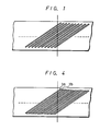
- a suspension of carbonyl iron (Fe 3 0 4 ) and a diluent such as a volatile liquid of "Freon” is coated on a predetermined area of this linearity standard magnetic tape and then a magnetized pattern in particular record tracks on the magnetic tape are developed or made visible as shown in Fig. 1.
- the linearity is inspected by a so- called transverse method, in which the track distance between adjacent points along a one-dot chain line is measured.
- the inspection signal is recorded on the linearity standard magnetic tape by using only one of the two magnetic video heads, there exist non-magnetized portions between adjacent record tracks.
- the linearity of the linearity standard magnetic tape can be measured by this transverse method.
- an ATF automatic track finding system is employed in which these pilot signals are used to control the tracking of the video heads.
- the magnetized tracks can visibly not be distinguished from each other even if the afore-noted coating is used, and so it is impossible to measure the linearity of the magnetized tracks during manufacturing process of the tape.
- ATF automated track finding
- VTR video tape recorder
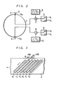
- Fig. 2 is a circuit diagram including constructional features of a video tape recorder (VTR) that is used in manufacturing a linearity standard magnetic tape of this invention
- Fig. 3 is a diagram showing a track pattern that is formed on a magnetic tape produced by the method of this invention.
- VTR video tape recorder
- references HA and HB designate magnetic video heads having different azimuth gaps that are mounted on a rotary drum 1 so as to form slant tracks on a magnetic tape 2.
- Reference numerals 3 and 4 designate tape guides that lead the magnetic tape 2 to a predetermined position.
- Reference numerals 5 and 6 designate change-over switches, reference numerals 7 and 8,respectively, designate adding circuits, and reference numerals 9 and 10,respectively, designate oscillating circuits that produce signals of 9 MHz and 1 MHz. These two frequency values are presently preferred but are not mandatory.
- the lower frequency value of the two is remarkably higher than the above mentioned four low frequency pilot signals but still within a frequency range that can well be recorded and reproduced via the rotary magnetic heads, whereas the higher frequency value is selected from a frequency range above the frequency recording and reproducing capability of the heads and/or the magnetic tape. Further details in respect to those two frequency values will be given below.
- pilot signals f l , f 2 , f 3 and f 4 for AT F are sequentially and repeatedly supplied through the change-over switches 5 and 6 to the two magnetic video heads HA and HB having different azimuth gaps, respectively.
- a signal of the relatively lower frequency is supplied to the magnetic video head HB, for example, said signal of 1 MHz that is used to measure the linearity of the track, while a signal of the relatively higher frequency, is supplied to the magnetic video head HA, for example, said signal of 9 MHz that has an AC bias effect for the pilot signal but does not remain as a record.
- tracks are formed on the magnetic tape 2 which repeatedly include the pilot signals fit f 21 f 3 and f 4 .
- a suspension of carbonyl iron and diluent is coated on the predetermined area of the standard linearity magnetic tape and then this tape area is developed as shown in Fig. 4, a track la on which the signal of 1 MHz is recorded is developed and made visible, but a track lb to which the signal of 9 MHz is applied remains invisible. That is, the track la on which the signal of 1 MHz is recorded can be made visible and this track la is formed at every other track position so that similarly to the prior art, it is possible to measure the linearity of the track by the above described transverse inspection method.
- the VTR is placed in the playback mode and the heights of the tape guides are adjusted by observing the envelope pattern of the signal of the relatively lower frequency, e.g. the 1 MHz signal that is reproduced from the magnetic video head HB and visualized on an oscilloscope (see e.g.”The Radio and Electronic Engineer", Vol. 44, No. 6, June 1974, p. 307 to 311).
- the tracking of the VTR can correctly be controlled by using these pilot signals f l , f 2 , f 3 and f 4 .
- the frequency range recordable on the tape depends on the characteristic of the magnetic head used for recording and the characteristic of the magnetic tape. Therefore, it is desired that the oscillation frequency of the oscillating circuit 9 is selected to be in a range of about 6 to 11 MHz because the signal therefrom is acting as the AC bias for the pilot signal but should not remain as a recording on the tape.
- the oscillation frequency of the oscillating circuit 10 is selected from a range of about 1 to 5 MHz.
Landscapes
- Engineering & Computer Science (AREA)
- Signal Processing (AREA)
- Adjustment Of The Magnetic Head Position Track Following On Tapes (AREA)
- Recording Or Reproducing By Magnetic Means (AREA)
- Testing, Inspecting, Measuring Of Stereoscopic Televisions And Televisions (AREA)
- Paints Or Removers (AREA)
Priority Applications (1)
| Application Number | Priority Date | Filing Date | Title |
|---|---|---|---|
| AT84115730T ATE50881T1 (de) | 1983-12-26 | 1984-12-18 | Verfahren zur realisierung eines linear standardisierten magnetischen bandes. |
Applications Claiming Priority (2)
| Application Number | Priority Date | Filing Date | Title |
|---|---|---|---|
| JP58251877A JPS60138702A (ja) | 1983-12-26 | 1983-12-26 | 記録トラツクの直線性測定法 |
| JP251877/83 | 1983-12-26 |
Publications (3)
| Publication Number | Publication Date |
|---|---|
| EP0147773A2 true EP0147773A2 (de) | 1985-07-10 |
| EP0147773A3 EP0147773A3 (en) | 1987-09-02 |
| EP0147773B1 EP0147773B1 (de) | 1990-03-07 |
Family
ID=17229259
Family Applications (1)
| Application Number | Title | Priority Date | Filing Date |
|---|---|---|---|
| EP84115730A Expired - Lifetime EP0147773B1 (de) | 1983-12-26 | 1984-12-18 | Verfahren zur Realisierung eines linear standardisierten magnetischen Bandes |
Country Status (7)
| Country | Link |
|---|---|
| US (1) | US4638388A (de) |
| EP (1) | EP0147773B1 (de) |
| JP (1) | JPS60138702A (de) |
| KR (1) | KR930006581B1 (de) |
| AT (1) | ATE50881T1 (de) |
| CA (1) | CA1274915A (de) |
| DE (1) | DE3481563D1 (de) |
Cited By (1)
| Publication number | Priority date | Publication date | Assignee | Title |
|---|---|---|---|---|
| EP0440396A3 (en) * | 1990-01-29 | 1993-01-13 | Matsushita Electric Industrial Co., Ltd. | Method of measuring track displacement on a magnetic tape |
Families Citing this family (1)
| Publication number | Priority date | Publication date | Assignee | Title |
|---|---|---|---|---|
| DE19852650A1 (de) * | 1998-11-16 | 2000-05-25 | Joerg Bobzin | Elektrische Maschine |
Family Cites Families (3)
| Publication number | Priority date | Publication date | Assignee | Title |
|---|---|---|---|---|
| JPS5150492U (de) * | 1974-10-16 | 1976-04-16 | ||
| US4489354A (en) * | 1980-11-24 | 1984-12-18 | Eastman Kodak Company | Information recording system with recording process monitoring function |
| JPS58150162A (ja) * | 1982-03-03 | 1983-09-06 | Hitachi Ltd | 磁気記録再生装置 |
-
1983
- 1983-12-26 JP JP58251877A patent/JPS60138702A/ja active Granted
-
1984
- 1984-12-18 DE DE8484115730T patent/DE3481563D1/de not_active Expired - Lifetime
- 1984-12-18 EP EP84115730A patent/EP0147773B1/de not_active Expired - Lifetime
- 1984-12-18 AT AT84115730T patent/ATE50881T1/de not_active IP Right Cessation
- 1984-12-20 CA CA000470626A patent/CA1274915A/en not_active Expired - Lifetime
- 1984-12-21 US US06/685,122 patent/US4638388A/en not_active Expired - Lifetime
- 1984-12-24 KR KR1019840008315A patent/KR930006581B1/ko not_active Expired - Fee Related
Non-Patent Citations (3)
| Title |
|---|
| IBM TECHNICAL DISCLOSURE BULLETIN, vol. 5, no. 5, October 1962, pages 36-37, New York, US; W.J. STEINGRANDT: "Magnetic pattern viewer" * |
| PHILIPS TECHNICAL REVIEW, vol. 40, no. 5, 1982, pages 129-132, Eindhoven, NL; A.M.A. RIJCKAERT: "Making the tracks on video tape visible with a magnetic fluid" * |
| SMPTE JOURNAL, vol. 88, no. 12, December 1979, pages 823-831, New York, US; H.L. ZAHN: "The BCN system for magnetic recording of television programs" * |
Cited By (1)
| Publication number | Priority date | Publication date | Assignee | Title |
|---|---|---|---|---|
| EP0440396A3 (en) * | 1990-01-29 | 1993-01-13 | Matsushita Electric Industrial Co., Ltd. | Method of measuring track displacement on a magnetic tape |
Also Published As
| Publication number | Publication date |
|---|---|
| EP0147773A3 (en) | 1987-09-02 |
| KR930006581B1 (ko) | 1993-07-21 |
| KR850004837A (ko) | 1985-07-27 |
| US4638388A (en) | 1987-01-20 |
| CA1274915A (en) | 1990-10-02 |
| ATE50881T1 (de) | 1990-03-15 |
| JPH056721B2 (de) | 1993-01-27 |
| JPS60138702A (ja) | 1985-07-23 |
| EP0147773B1 (de) | 1990-03-07 |
| DE3481563D1 (de) | 1990-04-12 |
Similar Documents
| Publication | Publication Date | Title |
|---|---|---|
| EP0147773B1 (de) | Verfahren zur Realisierung eines linear standardisierten magnetischen Bandes | |
| EP0329395B1 (de) | Magnetisches Aufzeichnungs- und Wiedergabegerät | |
| US5459617A (en) | Apparatus and methods for recording information signals and tracking signals on magnetic tape | |
| CA1261965A (en) | Video signal recording apparatus | |
| EP0198647B1 (de) | Verfahren und Vorrichtung zur Entdeckung eines toten Bereichs in der Übergangsfunktion einer Signalverarbeitungsanordnung | |
| US5737146A (en) | Data recording and playback apparatus using a helical scan system with magnetic head for recording and playing back pattern signal for tracking in tracking area within helical track | |
| CN1008843B (zh) | 制造标准线性度磁带的方法 | |
| US4843491A (en) | Recording and reproducing apparatus with track pitch detection | |
| JP2646997B2 (ja) | テープスピード測定方法 | |
| JP2533082B2 (ja) | 規準テ−プ | |
| US4802031A (en) | Tracking control using signals reproduced by erase head | |
| EP0316954A3 (de) | Wiedergabeverfahren für Bandrekorder mit Drehkopf | |
| JP2510325B2 (ja) | 磁気記録再生装置の調整装置 | |
| SU1224824A1 (ru) | Способ контрол годности двухдорожечного блока записывающих магнитных головок дл установки в магнитофон | |
| JPS60160052A (ja) | Vtr調整用テ−プ | |
| KR100207714B1 (ko) | 불량 컨트롤 신호 재생장치 및 방법 | |
| EP0357352A2 (de) | Videosignalaufzeichnungs-/-wiedergabegerät | |
| JP3227903B2 (ja) | 磁気記録再生装置の調整装置 | |
| JPH0246501A (ja) | テープ走行調整用磁気テープ及びテープ走行調整検査方法 | |
| Pichler et al. | Criteria for the Selection of Audio Tapes for Analog and Digital Recording According to their Drop-Out Characteristic | |
| JPH01140402A (ja) | R−datの信号記録方式 | |
| JPH06168515A (ja) | 磁気記録再生装置 | |
| JPS6412002B2 (de) | ||
| JPS63171413A (ja) | 磁気ヘツドの試験装置 | |
| JPS58121160A (ja) | 検査用磁気テ−プ |
Legal Events
| Date | Code | Title | Description |
|---|---|---|---|
| PUAI | Public reference made under article 153(3) epc to a published international application that has entered the european phase |
Free format text: ORIGINAL CODE: 0009012 |
|
| AK | Designated contracting states |
Designated state(s): AT DE FR GB IT NL |
|
| PUAL | Search report despatched |
Free format text: ORIGINAL CODE: 0009013 |
|
| AK | Designated contracting states |
Kind code of ref document: A3 Designated state(s): AT DE FR GB IT NL |
|
| 17P | Request for examination filed |
Effective date: 19880301 |
|
| 17Q | First examination report despatched |
Effective date: 19880726 |
|
| GRAA | (expected) grant |
Free format text: ORIGINAL CODE: 0009210 |
|
| AK | Designated contracting states |
Kind code of ref document: B1 Designated state(s): AT DE FR GB IT NL |
|
| REF | Corresponds to: |
Ref document number: 50881 Country of ref document: AT Date of ref document: 19900315 Kind code of ref document: T |
|
| ET | Fr: translation filed | ||
| REF | Corresponds to: |
Ref document number: 3481563 Country of ref document: DE Date of ref document: 19900412 |
|
| ITF | It: translation for a ep patent filed | ||
| PLBE | No opposition filed within time limit |
Free format text: ORIGINAL CODE: 0009261 |
|
| STAA | Information on the status of an ep patent application or granted ep patent |
Free format text: STATUS: NO OPPOSITION FILED WITHIN TIME LIMIT |
|
| 26N | No opposition filed | ||
| ITTA | It: last paid annual fee | ||
| PGFP | Annual fee paid to national office [announced via postgrant information from national office to epo] |
Ref country code: FR Payment date: 20011212 Year of fee payment: 18 Ref country code: AT Payment date: 20011212 Year of fee payment: 18 |
|
| PGFP | Annual fee paid to national office [announced via postgrant information from national office to epo] |
Ref country code: GB Payment date: 20011219 Year of fee payment: 18 |
|
| PGFP | Annual fee paid to national office [announced via postgrant information from national office to epo] |
Ref country code: NL Payment date: 20011228 Year of fee payment: 18 |
|
| REG | Reference to a national code |
Ref country code: GB Ref legal event code: IF02 |
|
| PGFP | Annual fee paid to national office [announced via postgrant information from national office to epo] |
Ref country code: DE Payment date: 20020109 Year of fee payment: 18 |
|
| PG25 | Lapsed in a contracting state [announced via postgrant information from national office to epo] |
Ref country code: GB Free format text: LAPSE BECAUSE OF NON-PAYMENT OF DUE FEES Effective date: 20021218 Ref country code: AT Free format text: LAPSE BECAUSE OF NON-PAYMENT OF DUE FEES Effective date: 20021218 |
|
| PG25 | Lapsed in a contracting state [announced via postgrant information from national office to epo] |
Ref country code: NL Free format text: LAPSE BECAUSE OF NON-PAYMENT OF DUE FEES Effective date: 20030701 Ref country code: DE Free format text: LAPSE BECAUSE OF NON-PAYMENT OF DUE FEES Effective date: 20030701 |
|
| GBPC | Gb: european patent ceased through non-payment of renewal fee |
Effective date: 20021218 |
|
| NLV4 | Nl: lapsed or anulled due to non-payment of the annual fee |
Effective date: 20030701 |
|
| PG25 | Lapsed in a contracting state [announced via postgrant information from national office to epo] |
Ref country code: FR Free format text: LAPSE BECAUSE OF NON-PAYMENT OF DUE FEES Effective date: 20030901 |
|
| REG | Reference to a national code |
Ref country code: FR Ref legal event code: ST |