EP0147663B1 - Vorrichtung zum Herstellen von Gas - Google Patents
Vorrichtung zum Herstellen von Gas Download PDFInfo
- Publication number
- EP0147663B1 EP0147663B1 EP84114525A EP84114525A EP0147663B1 EP 0147663 B1 EP0147663 B1 EP 0147663B1 EP 84114525 A EP84114525 A EP 84114525A EP 84114525 A EP84114525 A EP 84114525A EP 0147663 B1 EP0147663 B1 EP 0147663B1
- Authority
- EP
- European Patent Office
- Prior art keywords
- raw material
- main
- liquid raw
- vessel
- replenishment
- Prior art date
- Legal status (The legal status is an assumption and is not a legal conclusion. Google has not performed a legal analysis and makes no representation as to the accuracy of the status listed.)
- Expired
Links
Images

Classifications
-
- C—CHEMISTRY; METALLURGY
- C03—GLASS; MINERAL OR SLAG WOOL
- C03B—MANUFACTURE, SHAPING, OR SUPPLEMENTARY PROCESSES
- C03B37/00—Manufacture or treatment of flakes, fibres, or filaments from softened glass, minerals, or slags
- C03B37/08—Bushings, e.g. construction, bushing reinforcement means; Spinnerettes; Nozzles; Nozzle plates
- C03B37/085—Feeding devices therefor
-
- B—PERFORMING OPERATIONS; TRANSPORTING
- B01—PHYSICAL OR CHEMICAL PROCESSES OR APPARATUS IN GENERAL
- B01J—CHEMICAL OR PHYSICAL PROCESSES, e.g. CATALYSIS OR COLLOID CHEMISTRY; THEIR RELEVANT APPARATUS
- B01J4/00—Feed or outlet devices; Feed or outlet control devices
- B01J4/008—Feed or outlet control devices
-
- C—CHEMISTRY; METALLURGY
- C03—GLASS; MINERAL OR SLAG WOOL
- C03B—MANUFACTURE, SHAPING, OR SUPPLEMENTARY PROCESSES
- C03B37/00—Manufacture or treatment of flakes, fibres, or filaments from softened glass, minerals, or slags
- C03B37/01—Manufacture of glass fibres or filaments
- C03B37/012—Manufacture of preforms for drawing fibres or filaments
- C03B37/014—Manufacture of preforms for drawing fibres or filaments made entirely or partially by chemical means, e.g. vapour phase deposition of bulk porous glass either by outside vapour deposition [OVD], or by outside vapour phase oxidation [OVPO] or by vapour axial deposition [VAD]
- C03B37/01413—Reactant delivery systems
-
- C—CHEMISTRY; METALLURGY
- C03—GLASS; MINERAL OR SLAG WOOL
- C03C—CHEMICAL COMPOSITION OF GLASSES, GLAZES OR VITREOUS ENAMELS; SURFACE TREATMENT OF GLASS; SURFACE TREATMENT OF FIBRES OR FILAMENTS MADE FROM GLASS, MINERALS OR SLAGS; JOINING GLASS TO GLASS OR OTHER MATERIALS
- C03C17/00—Surface treatment of glass, not in the form of fibres or filaments, by coating
- C03C17/02—Surface treatment of glass, not in the form of fibres or filaments, by coating with glass
-
- C—CHEMISTRY; METALLURGY
- C23—COATING METALLIC MATERIAL; COATING MATERIAL WITH METALLIC MATERIAL; CHEMICAL SURFACE TREATMENT; DIFFUSION TREATMENT OF METALLIC MATERIAL; COATING BY VACUUM EVAPORATION, BY SPUTTERING, BY ION IMPLANTATION OR BY CHEMICAL VAPOUR DEPOSITION, IN GENERAL; INHIBITING CORROSION OF METALLIC MATERIAL OR INCRUSTATION IN GENERAL
- C23C—COATING METALLIC MATERIAL; COATING MATERIAL WITH METALLIC MATERIAL; SURFACE TREATMENT OF METALLIC MATERIAL BY DIFFUSION INTO THE SURFACE, BY CHEMICAL CONVERSION OR SUBSTITUTION; COATING BY VACUUM EVAPORATION, BY SPUTTERING, BY ION IMPLANTATION OR BY CHEMICAL VAPOUR DEPOSITION, IN GENERAL
- C23C16/00—Chemical coating by decomposition of gaseous compounds, without leaving reaction products of surface material in the coating, i.e. chemical vapour deposition [CVD] processes
- C23C16/44—Chemical coating by decomposition of gaseous compounds, without leaving reaction products of surface material in the coating, i.e. chemical vapour deposition [CVD] processes characterised by the method of coating
- C23C16/448—Chemical coating by decomposition of gaseous compounds, without leaving reaction products of surface material in the coating, i.e. chemical vapour deposition [CVD] processes characterised by the method of coating characterised by the method used for generating reactive gas streams, e.g. by evaporation or sublimation of precursor materials
- C23C16/4481—Chemical coating by decomposition of gaseous compounds, without leaving reaction products of surface material in the coating, i.e. chemical vapour deposition [CVD] processes characterised by the method of coating characterised by the method used for generating reactive gas streams, e.g. by evaporation or sublimation of precursor materials by evaporation using carrier gas in contact with the source material
- C23C16/4482—Chemical coating by decomposition of gaseous compounds, without leaving reaction products of surface material in the coating, i.e. chemical vapour deposition [CVD] processes characterised by the method of coating characterised by the method used for generating reactive gas streams, e.g. by evaporation or sublimation of precursor materials by evaporation using carrier gas in contact with the source material by bubbling of carrier gas through liquid source material
-
- C—CHEMISTRY; METALLURGY
- C03—GLASS; MINERAL OR SLAG WOOL
- C03B—MANUFACTURE, SHAPING, OR SUPPLEMENTARY PROCESSES
- C03B2207/00—Glass deposition burners
- C03B2207/80—Feeding the burner or the burner-heated deposition site
- C03B2207/81—Constructional details of the feed line, e.g. heating, insulation, material, manifolds, filters
-
- C—CHEMISTRY; METALLURGY
- C03—GLASS; MINERAL OR SLAG WOOL
- C03B—MANUFACTURE, SHAPING, OR SUPPLEMENTARY PROCESSES
- C03B2207/00—Glass deposition burners
- C03B2207/80—Feeding the burner or the burner-heated deposition site
- C03B2207/85—Feeding the burner or the burner-heated deposition site with vapour generated from liquid glass precursors, e.g. directly by heating the liquid
- C03B2207/86—Feeding the burner or the burner-heated deposition site with vapour generated from liquid glass precursors, e.g. directly by heating the liquid by bubbling a gas through the liquid
-
- Y—GENERAL TAGGING OF NEW TECHNOLOGICAL DEVELOPMENTS; GENERAL TAGGING OF CROSS-SECTIONAL TECHNOLOGIES SPANNING OVER SEVERAL SECTIONS OF THE IPC; TECHNICAL SUBJECTS COVERED BY FORMER USPC CROSS-REFERENCE ART COLLECTIONS [XRACs] AND DIGESTS
- Y10—TECHNICAL SUBJECTS COVERED BY FORMER USPC
- Y10T—TECHNICAL SUBJECTS COVERED BY FORMER US CLASSIFICATION
- Y10T137/00—Fluid handling
- Y10T137/4238—With cleaner, lubrication added to fluid or liquid sealing at valve interface
- Y10T137/4245—Cleaning or steam sterilizing
- Y10T137/4252—Reverse fluid flow
Definitions
- the present invention generally relates to gas supplying apparatuses and is applicable to a gas supplying apparatus which supplies to a processing apparatus gaseous raw material including vapor of liquid raw material.
- an optical fiber reaction apparatus gaseous raw material out of which the optical fiber is to be formed, which is constituted by carrier gas mixed with vapor of liquid raw material, with the liquid raw material being silicon tetrachloride or germanium tetrachloride.
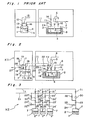
- a prior art gas supplying apparatus according to the preamble of claim 1 and which has been conventionally used by applicant for supplying the gaseous raw material out of which the optical fiber is to be formed to the optical fiber reaction apparatus will be described with reference to Fig.1.
- a main vessel 2 containing liquid raw material 1 of the optical fiber is secured to a bottom portion of a constant temperature bath 3 directly or through a support base, the liquid raw material 1 is maintained at a predetermined temperature.
- Carrier gas 4 is introduced, through a pipe 6 provided with a flow regulator 5 and dipped into the liquid raw material 1 of the main vessel 2, so as to bubble the liquid raw material 1 as shown in Fig. 1.
- the carrier gas 4 is mixed with the liquid raw material 1 to a saturated state or an almost saturated state so as to be formed into gaseous raw material 7.
- the gaseous raw material 7 is supplied to the optical fiber reaction apparatus via a pipe 8.
- the carrier gas 4 since the carrier gas 4 is not necessarily required to bubble the liquid raw material 1, it can be also so arranged that the carrier gas 4 is simply introduced over a liquid level of the liquid raw material 1 in the main vessel 2 so as to be mixed with vapor of the liquid raw material 1 into the gaseous raw material 7.
- the liquid raw material 1 for replenishment is stored in an auxiliary vessel 9 connected with a pipe 10.
- an inlet end 11a a of a main pipe 11 is dipped in the liquid raw material 1 stored in the auxiliary vessel 9, while an outlet end 11b of the main pipe 11 is disposed in the main vessel 2 and above the liquid level of the liquid raw material 1 in the main vessel 2.
- the known gas supplying apparatus includes control valves 12 to 18.
- the control valves 12 and 13 are opened. Meanwhile, when the gaseous raw material 7 is continuously supplied to the optical fiber reaction apparatus and thus, the liquid raw material 1 stored in the main vessel 2 decreases in amount, the main vessel 2 is replenished with the liquid raw material 1 stored in the auxiliary vessel 9.
- the control valves 14 and 17 are closed and the control valves 15, 16 and 18 are opened, while pressurized nitrogen gas 19 is fed into the auxiliary vessel 9 through the pipe 10.
- the main vessel 2 is replenished, through the main pipe 11, with the liquid raw material 1 in the auxiliary vessel 9 by the pressurized nitrogen gas 19.
- a primary replenishment hereinbelow.
- the open control valves 16 and 18 are closed and the closed control valve 17 is opened.
- the liquid raw material 1 remaining in the main pipe 11 is fed under pressure into the main vessel 2.by the pressurized nitrogen gas 19.
- this replenishment of the liquid raw material 1 into the main vessel 2 is referred to as a "secondary replenishment", hereinbelow.
- the prior art gas supplying apparatus of Fig. 1 has the following drawbacks (1) and (2). (1) In the case where the single main vessel 2 is replenished with the liquid raw material 1 in the single auxiliary vessel 9.
- a total replenishment amount of the liquid raw material 1 should be set on the basis of two replenishment amounts of the liquid raw material 1 based on the primary replenishment and the secondary replenishment, thereby resulting in difficulty in setting the total replenishment amount of the liquid raw material 1. Furthermore, in the case where the main pipe 11 is replaced with a new one having a length and a diameter different from those of the main pipe 11, the replenishment amount of the liquid raw material 1 based on the secondary replenishment directly changes accordingly, so that it becomes necessary to set the total replenishment amount of the liquid raw material 1 again, which is a troublesome operation. (2) In the case where a plurality of the main vessels 2 are replenished with the liquid raw material 1 in the single auxiliary vessel 9:
- the replenishment amounts of the liquid raw material 1 for the respective main vessels 2 based on the secondary replenishment are different from one another. Accordingly, when amounts of the liquid raw material 1 in the respective main vessels 2 should be set at a predetermined value, the replenishment amounts of the liquid raw material 1 for the respective main vessels 2 based on the secondary replenishment are required to be set at different values for the main vessels 2, respectively, which is quite troublesome. Especially, in the case where a number of the main vessels 2 are scattered at various spots with the result that the long main pipes 11 are installed complicatedly, the above described disadvantage of the known gas supplying apparatus becomes quite serious.
- an object of the present invention is to provide an improved gas supplying apparatus which supplies to a processing apparatus gaseous raw material including vapor of liquid raw material so as to efficiently perform replenishment of the liquid raw material, with substantial elimination of the disadvantages inherent in conventional gas supplying apparatuses of this kind.
- gas supplying apparatus for supplying gaseous raw material to a processing apparatus, comprising: at least one main vessel for storing liquid raw material, which generates said gaseous raw material constituted by vapor of said liquid raw material mixed with carrier gas by drawing said carrier gas into said main vessel so as to supply said gaseous raw material to said processing apparatus; an auxiliary vessel for storing replenishment of liquid raw material for said at least one main vessel; a main pipe for delivering to said at least one main vessel said replenishment of liquid raw material stored in said auxiliary vessel, which main pipe has an inlet end and an outlet end; said inlet end being dipped in said replenishment of liquid raw material in said auxiliary vessel, while said outlet end is disposed in said at least one main vessel and above the liquid level of the liquid raw material in the main vessel; and a feed means for feeding, through said main pipe, to said main vessel said replenishment of liquid raw material in said auxiliary vessel, which gas supplying apparatus is, according to the present invention, characterized by; a return pipe, to said main vessel said replenishment of liquid
- the apparatus K1 includes a main vessel 2 containing liquid raw material 1 of the optical fiber, a constant temperature bath 3, a pipe 6 provided with a flow regulator 5, a pipe 8, an auxiliary vessel 9 containing the liquid raw material 1 for replenishment, a pipe 10 for feeding pressurized nitrogen gas 19 therethrough into the auxiliary vessel 9, a main pipe 11 having an inlet end 11 a and an outlet end 11 b, and control valves 12 and 13 and 16 to 18 and 23 in the same manner as in the prior art gas supplying apparatus of Fig.
- the liquid raw material 1 stored in the main vessel 2 is maintained at a predetermined temperature.
- Carrier gas 4 is introduced through the pipe 6 dipped into the liquid raw material 1 of the main vessel 2, so as to bubble the liquid raw material 1.
- the carrier gas 4 is mixed with the liquid raw material 1 to a saturated state or an almost saturated state so as to be formed into the gaseous raw material 7.
- the liquid raw material 7 is supplied to the optical fiber reaction apparatus via the pipe 8.
- the carrier gas 4 is not necessarily required to bubble the liquid raw material 1, it can be also so arranged that the carrier gas 4 is simply introduced over a liquid level of the liquid raw material 1 in the main vessel 2 so as to be mixed with vapor of the liquid raw material 1 into the gaseous raw material 7.
- the inlet end 11a of the main pipe 11 is dipped in the liquid raw material 1 stored in the auxiliary vessel 9, while the outlet end 11b b of the main pipe 11 is disposed in the main vessel 2 and above the liquid level of the liquid raw material 1 in the main vessel 2.
- the apparatus K1 includes a return pipe 21 provided with a control valve 22, a control valve 23, a pipe 25 provided with a control valve 24, and a pipe 27 provided with a control valve 26.
- the return pipe 21 is branched, in the vicinity of the outlet end 11 b, at a branch point 11 c from the main pipe 11.
- a distal end 21 a of the return pipe 21 is disposed in the auxiliary vessel 9 and above a liquid level of the liquid raw material 1 in the auxiliary vessel 9.
- the control valve 23 is provided between the branch point 11 c and the outlet end 11b of the main pipe 11.
- the pipe 25 is connected with the main pipe 11 between the control valve 23 and the outlet end 11 b.
- the pipe 27 is connected with the auxiliary vessel 9.
- the control valves 17, 22, 24 and 26 are closed and the control valves 16, 18 and 23 are opened, so that the pressurized nitrogen gas 19 is fed into the auxiliary vessel 9 through the pipe 10.
- the liquid raw material 1 stored in the auxiliary vessel 9 is carried into the main vessel 2 via the main pipe 11.
- the control valves 16,18,23 and 24 are closed and the control valves 17, 22 and 26 are opened, so that supply of the liquid raw material 1 of the auxiliary vessel 9 to the main vessel 2 is stopped and the liquid raw material 1 remaining in the main pipe 11 is returned, through the return pipe 21, to the auxiliary vessel 9.
- the liquid raw material 1 in the auxiliary vessel 9 is prevented, after the liquid raw material 1 remaining in the main pipe 11 has been returned to the auxiliary vessel 9, from being bubbled by the pressurized nitrogen gas 19 injected from the distal end 21 a.
- the liquid raw material 1 remaining in the main pipe 11 between the control valve 23 and the outlet end 11b is carried into the main vessel 2. Meanwhile, since an amount of the liquid raw material 1 remaining in the main pipe 11 between the control valve 23 and the outlet end 11 b is quite small compared with a total replenishment amount of the liquid raw material 1, the total replenishment amount of the liquid raw material 1 is substantially determined by an amount of the liquid raw material 1 fed at the time when the control valve 23 is opened.
- the total replenishment amount of the liquid raw material 1 is substantially determined by the amount of the liquid raw material 1 fed at the time when the control valve 23 is opened in the apparatus K1 as described above, it becomes easy to accurately set the total replenishment amount of the liquid raw material 1 at a target value even if the main pipe 11 varies in length or diameter.
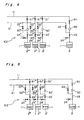
- a gas supplying apparatus K2 in which a plurality of main vessels 2, 2', 2" and 2"' are replenished with the liquid raw material 1 in the single auxiliary vessel 9 (not shown).
- the main vessels 2, 2', 2" and 2"' are connected, through flow regulators 30, 30', 30" and 30'" and opening and closing valves 31, 31', 31" and 31 "', with the main pipe 11, respectively. Meanwhile, it is so arranged that the gaseous raw material 7 generated in the main vessels 2, 2', 2" and 2"' is supplied to the optical fiber reaction apparatus through pipes (not shown).
- the apparatus K2 includes the return pipe 21, main control valves 22, 22', 22" and 22"', control valves 23, 23', 23" and 23'" and control valves 24, 24', 24" and 24"' and pipes 25, 25', 25" and 25”' in the same manner as in the apparatus K1. Since other constructions of the apparatus K2 are similar to those of the apparatus K1, detailed description thereof is abbreviated for the sake of brevity.
- the opening and closing valve 31 and the control valve 22 are initially opened as shown in Fig. 7 so as to feed the liquid raw material 1 under pressure in a path A in Fig. 7.
- the opening and closing valve 31" and the control valve 22" are opened as shown in Fig. 8 so as to feed the liquid raw material 1 under pressure in a path B in Fig. 8.
- the apparatus K2 it becomes possible to replenish each of the main vessels 2, 2', 2" and 2'" with the target amount of the liquid raw material 1 accurately. Furthermore, in the apparatus K2, it becomes possible to simultaneously replenish a plurality of the main vessels 2, 2', 2" and 2"' with the liquid raw material 1, thereby increasing operating efficiency of the gas supplying apparatus. Moreover, since the main pipe 11 and the return pipe 21 can be used, in common, for the main vessels 2, 2', 2" and 2"', piping of the gas supplying apparatus can be performed easily.
- pressurized nitrogen gas is used for replenishing the main vessel with the liquid raw material in the apparatuses K1 and K2
- a pump or any other feed means can also be used in place of the pressurized nitrogen gas.
- pressurized gas is required to be used for returning to the auxiliary vessel the liquid raw material remaining in the main pipe.
- the present invention can be applied not only to the gas supplying apparatus for supplying the gaseous raw material out of which the optical fiber is to be formed but to any other gas supply apparatus.
- the main vessel can be replenished with the target amount of the liquid raw material accurately and efficiently.
Landscapes
- Chemical & Material Sciences (AREA)
- Engineering & Computer Science (AREA)
- Organic Chemistry (AREA)
- Chemical Kinetics & Catalysis (AREA)
- Materials Engineering (AREA)
- General Chemical & Material Sciences (AREA)
- Geochemistry & Mineralogy (AREA)
- Life Sciences & Earth Sciences (AREA)
- General Life Sciences & Earth Sciences (AREA)
- Manufacturing & Machinery (AREA)
- Mechanical Engineering (AREA)
- Metallurgy (AREA)
- Feeding, Discharge, Calcimining, Fusing, And Gas-Generation Devices (AREA)
- Glass Melting And Manufacturing (AREA)
- Manufacture, Treatment Of Glass Fibers (AREA)
- Loading And Unloading Of Fuel Tanks Or Ships (AREA)
Claims (5)
Applications Claiming Priority (2)
| Application Number | Priority Date | Filing Date | Title |
|---|---|---|---|
| JP226750/83 | 1983-12-02 | ||
| JP58226750A JPS60122735A (ja) | 1983-12-02 | 1983-12-02 | 原料ガス供給装置 |
Publications (2)
| Publication Number | Publication Date |
|---|---|
| EP0147663A1 EP0147663A1 (de) | 1985-07-10 |
| EP0147663B1 true EP0147663B1 (de) | 1987-09-09 |
Family
ID=16850019
Family Applications (1)
| Application Number | Title | Priority Date | Filing Date |
|---|---|---|---|
| EP84114525A Expired EP0147663B1 (de) | 1983-12-02 | 1984-11-30 | Vorrichtung zum Herstellen von Gas |
Country Status (6)
| Country | Link |
|---|---|
| US (1) | US4563312A (de) |
| EP (1) | EP0147663B1 (de) |
| JP (1) | JPS60122735A (de) |
| KR (1) | KR870001278B1 (de) |
| CA (1) | CA1237047A (de) |
| DE (1) | DE3465976D1 (de) |
Families Citing this family (14)
| Publication number | Priority date | Publication date | Assignee | Title |
|---|---|---|---|---|
| JPS60244333A (ja) * | 1984-05-21 | 1985-12-04 | Sumitomo Electric Ind Ltd | 原料液補給装置 |
| US4859375A (en) * | 1986-12-29 | 1989-08-22 | Air Products And Chemicals, Inc. | Chemical refill system |
| JPH0824836B2 (ja) * | 1986-10-09 | 1996-03-13 | 東洋紡績株式会社 | 液体の連続供給装置 |
| DE3708967A1 (de) * | 1987-03-19 | 1988-10-06 | Merck Patent Gmbh | Vorrichtung zur erzeugung eines gasgemisches nach dem saettigungsverfahren |
| JP2554356B2 (ja) * | 1988-05-17 | 1996-11-13 | 住友電気工業株式会社 | ガラス原料供給方法及びガラス原料供給装置 |
| JP2846891B2 (ja) * | 1988-06-03 | 1999-01-13 | 東京エレクトロン株式会社 | 処理装置 |
| US4904419A (en) * | 1989-03-14 | 1990-02-27 | Reynolds Warren D | Process and apparatus for vapor transfer of very high purity liquids at high dilution |
| GB9206552D0 (en) * | 1992-03-26 | 1992-05-06 | Epichem Ltd | Bubblers |
| JPH0781965A (ja) * | 1993-07-22 | 1995-03-28 | Sumitomo Electric Ind Ltd | ガス生成装置並びに光導波路及び光ファイバ母材を製造する方法及び装置 |
| TW338174B (en) * | 1995-01-06 | 1998-08-11 | Tokyo Electron Co Ltd | Apparatus for supplying a treatment material |
| KR100524204B1 (ko) * | 1998-01-07 | 2006-01-27 | 동경 엘렉트론 주식회사 | 가스 처리장치 |
| DE502004012396D1 (de) | 2004-02-20 | 2011-05-26 | Cs Clean Systems Ag | Vorrichtung und Verfahren zum Nachfüllen eines Blasenverdampfers |
| US9914632B2 (en) * | 2014-08-22 | 2018-03-13 | Applied Materials, Inc. | Methods and apparatus for liquid chemical delivery |
| CN111153590B (zh) * | 2019-12-31 | 2022-03-25 | 江苏通鼎光棒有限公司 | 一种高精度的四氯化锗鼓泡装置 |
Family Cites Families (7)
| Publication number | Priority date | Publication date | Assignee | Title |
|---|---|---|---|---|
| US2371188A (en) * | 1945-03-13 | Means fob clearing pipe systems | ||
| US2178559A (en) * | 1937-06-12 | 1939-11-07 | Beer Control Systems Inc | Fluid dispensing system |
| US2882539A (en) * | 1954-11-18 | 1959-04-21 | Walz Bruno | Tube cleaning mechanism |
| US3044466A (en) * | 1960-12-23 | 1962-07-17 | Gomco Surgical Mfg Corp | Valve and pump assembly for closing and irrigating fluid drainage tube in suction apparatus |
| US4276243A (en) * | 1978-12-08 | 1981-06-30 | Western Electric Company, Inc. | Vapor delivery control system and method |
| US4235829A (en) * | 1979-05-07 | 1980-11-25 | Western Electric Company, Inc. | Vapor delivery system and method of maintaining a constant level of liquid therein |
| US4313897A (en) * | 1980-01-30 | 1982-02-02 | Bruce Garrard | Gas and liquid admixing system |
-
1983
- 1983-12-02 JP JP58226750A patent/JPS60122735A/ja active Granted
-
1984
- 1984-11-30 DE DE8484114525T patent/DE3465976D1/de not_active Expired
- 1984-11-30 EP EP84114525A patent/EP0147663B1/de not_active Expired
- 1984-11-30 CA CA000469057A patent/CA1237047A/en not_active Expired
- 1984-12-01 KR KR1019840007594A patent/KR870001278B1/ko not_active Expired
- 1984-12-03 US US06/677,588 patent/US4563312A/en not_active Expired - Lifetime
Also Published As
| Publication number | Publication date |
|---|---|
| US4563312A (en) | 1986-01-07 |
| KR870001278B1 (ko) | 1987-06-30 |
| JPS6144824B2 (de) | 1986-10-04 |
| JPS60122735A (ja) | 1985-07-01 |
| DE3465976D1 (en) | 1987-10-15 |
| CA1237047A (en) | 1988-05-24 |
| EP0147663A1 (de) | 1985-07-10 |
| KR850004449A (ko) | 1985-07-15 |
Similar Documents
| Publication | Publication Date | Title |
|---|---|---|
| EP0147663B1 (de) | Vorrichtung zum Herstellen von Gas | |
| EP0165493B1 (de) | Nachfülleinrichtung für Flüssigkeiten | |
| US4861524A (en) | Apparatus for producing a gas mixture by the saturation method | |
| CA2106734C (en) | Apparatus for supplying cvd coating devices | |
| US6273954B2 (en) | System for manufacturing a semiconductor device | |
| EP0318395B1 (de) | Anlage zur metallorganischen chemischen Abscheidung aus der Gasphase sowie Verfahren zu deren Anwendung | |
| US7025337B2 (en) | Method for maintaining a constant level of fluid in a liquid vapor delivery system | |
| KR20100048894A (ko) | 재료가스 농도 제어 시스템 | |
| US6516824B2 (en) | Apparatus and method for metering delivery quantity of ultra-low temperature liquefied gas | |
| JPH0620977A (ja) | 液流を気流に変換する方法及び装置 | |
| US20050126483A1 (en) | Arrangement for depositing atomic layers on substrates | |
| US2389488A (en) | Method of agitation of pickling baths | |
| JPH11349397A (ja) | 連続供給単一バブラーを使用するシリコンのエピタキシャル堆積のための供給システム及び方法 | |
| US2463111A (en) | Strand coating and winding machine | |
| US3969922A (en) | Apparatus for feeding fuel to an engine | |
| KR100309395B1 (ko) | 원료물질공급장치 | |
| JPH0714770A (ja) | 液体ソース供給装置 | |
| US2062397A (en) | Apparatus for desuperheating steam | |
| JPS5937399A (ja) | 超低温液体の定量供給装置 | |
| JPH1187295A (ja) | 基板処理装置 | |
| JPH05315264A (ja) | 液体材料の気化供給方法及びその装置並びに化学気相成長システム | |
| JPS59116140A (ja) | 原料供給装置 | |
| KR20230154347A (ko) | 기판 처리 설비 및 기판 처리 방법 | |
| SU1216573A1 (ru) | Система теплоснабжени | |
| JPS5650997A (en) | Method for supplying vaporized lpg |
Legal Events
| Date | Code | Title | Description |
|---|---|---|---|
| PUAI | Public reference made under article 153(3) epc to a published international application that has entered the european phase |
Free format text: ORIGINAL CODE: 0009012 |
|
| AK | Designated contracting states |
Designated state(s): DE FR GB IT NL |
|
| 17P | Request for examination filed |
Effective date: 19850926 |
|
| 17Q | First examination report despatched |
Effective date: 19860704 |
|
| GRAA | (expected) grant |
Free format text: ORIGINAL CODE: 0009210 |
|
| AK | Designated contracting states |
Kind code of ref document: B1 Designated state(s): DE FR GB IT NL |
|
| ET | Fr: translation filed | ||
| REF | Corresponds to: |
Ref document number: 3465976 Country of ref document: DE Date of ref document: 19871015 |
|
| ITF | It: translation for a ep patent filed | ||
| PLBE | No opposition filed within time limit |
Free format text: ORIGINAL CODE: 0009261 |
|
| STAA | Information on the status of an ep patent application or granted ep patent |
Free format text: STATUS: NO OPPOSITION FILED WITHIN TIME LIMIT |
|
| 26N | No opposition filed | ||
| ITTA | It: last paid annual fee | ||
| PGFP | Annual fee paid to national office [announced via postgrant information from national office to epo] |
Ref country code: FR Payment date: 19971112 Year of fee payment: 14 |
|
| PGFP | Annual fee paid to national office [announced via postgrant information from national office to epo] |
Ref country code: NL Payment date: 19971130 Year of fee payment: 14 |
|
| PGFP | Annual fee paid to national office [announced via postgrant information from national office to epo] |
Ref country code: DE Payment date: 19971205 Year of fee payment: 14 |
|
| PG25 | Lapsed in a contracting state [announced via postgrant information from national office to epo] |
Ref country code: NL Free format text: LAPSE BECAUSE OF NON-PAYMENT OF DUE FEES Effective date: 19990601 |
|
| PG25 | Lapsed in a contracting state [announced via postgrant information from national office to epo] |
Ref country code: FR Free format text: LAPSE BECAUSE OF NON-PAYMENT OF DUE FEES Effective date: 19990730 |
|
| NLV4 | Nl: lapsed or anulled due to non-payment of the annual fee |
Effective date: 19990601 |
|
| REG | Reference to a national code |
Ref country code: FR Ref legal event code: ST |
|
| PG25 | Lapsed in a contracting state [announced via postgrant information from national office to epo] |
Ref country code: DE Free format text: LAPSE BECAUSE OF NON-PAYMENT OF DUE FEES Effective date: 19990901 |
|
| REG | Reference to a national code |
Ref country code: GB Ref legal event code: IF02 |
|
| PGFP | Annual fee paid to national office [announced via postgrant information from national office to epo] |
Ref country code: GB Payment date: 20031126 Year of fee payment: 20 |
|
| PG25 | Lapsed in a contracting state [announced via postgrant information from national office to epo] |
Ref country code: GB Free format text: LAPSE BECAUSE OF EXPIRATION OF PROTECTION Effective date: 20041129 |
|
| REG | Reference to a national code |
Ref country code: GB Ref legal event code: PE20 |