EP0146884A2 - Déflecteur réglable pour vitres de véhicles automobiles - Google Patents
Déflecteur réglable pour vitres de véhicles automobiles Download PDFInfo
- Publication number
- EP0146884A2 EP0146884A2 EP84115297A EP84115297A EP0146884A2 EP 0146884 A2 EP0146884 A2 EP 0146884A2 EP 84115297 A EP84115297 A EP 84115297A EP 84115297 A EP84115297 A EP 84115297A EP 0146884 A2 EP0146884 A2 EP 0146884A2
- Authority
- EP
- European Patent Office
- Prior art keywords
- shield
- air
- fact
- portions
- hinge joint
- Prior art date
- Legal status (The legal status is an assumption and is not a legal conclusion. Google has not performed a legal analysis and makes no representation as to the accuracy of the status listed.)
- Granted
Links
Images

Classifications
-
- B—PERFORMING OPERATIONS; TRANSPORTING
- B60—VEHICLES IN GENERAL
- B60J—WINDOWS, WINDSCREENS, NON-FIXED ROOFS, DOORS, OR SIMILAR DEVICES FOR VEHICLES; REMOVABLE EXTERNAL PROTECTIVE COVERINGS SPECIALLY ADAPTED FOR VEHICLES
- B60J1/00—Windows; Windscreens; Accessories therefor
- B60J1/20—Accessories, e.g. wind deflectors, blinds
Definitions
- the invention concerns an air shield suitable for use on the windows of the front doors of motor vehicles by being fitted onto the upper horizontal edge and downward sloping fore edge of the window itself.
- a scope of this invention is, therefore, to provide a single type of air shield, of the aforesaid kind, which is capable of adapting to the shapes and sizes of the windows of any given type of motor vehicle.
- a further scope of this invention is to provide an air shield, as described, made of separate parts which can be fitted together at the moment of use and which can consequently be packed and shipped in extremely compact conditions.
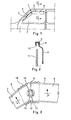
- Figure 1 shows a generic motor vehicle 1 in which the window 2 of each front door is provided with a substantially horizontal upper edge 3, and a downward sloping fore edge 4, whose size and angulation depend upon the features of the model of motor vehicle.
- Reference 5 moreover, indicates a generic air shield comprising a horizontal rear portion 6 and a downward sloping fore portion 7 which tapers off towards the front.
- the air shield 5, that is to say, the two portions 6 and 7 of which such shield is made up, may be secured to the edges 3 and 4 of the window 2 in any way, for example, as shown in figure 2, by forcing the upper edge 8 of each shield portion between the metal section 9 running along the edge of the window, and the internal weatherstrip 10, or in any other suitable way.
- the shield 5 has a suitably-shaped profile, as shown for example in figure 2, so as to remain spaced apart from the plane of the window 2, defined by the glass 11, thus forming a passage between the shield itself and the glass 11 which permits the ventilation of the inside of the motor vehicle and at the same time prevents strong currents of air or water from entering, even with the window wide open.
- the shield 5 is made up of a downward sloping fore portion 7, ending with a rounded point, and a horizontal rear portion 6; the two shield portions 6, 7 are hinged together by means of a hinge joint 12 situated in an intermediate position.
- the two shield portions 6, 7 present facing edges 13, 14 which diverge, starting from the joint itself, so as to allow, during the assembling of the shield, a relative rotation which enables the two shield portions 6 and 7 to place their upper edges 8 parallel with the edges 3 and 4 of the window.
- the facing edges 13 and/or 14 on at least one of the two shield portions it is advisable for the facing edges 13 and/or 14 on at least one of the two shield portions to form an angle ranging from 150° to 180° approximately, without excluding different angles in particular cases.
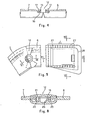
- the hinge joint 12 between the two shield portions 6 and 7 is achieved by means of a circular ring 15 which fits into corresponding semicircular seats provided on the two opposing ends of the shield portions 6 and 7; the circular ring 15 is provided with an annular flange 16 which forms a stopping surface for the two aforesaid shield portions. Since the two shield portions 6 and 7, once assembled, with the required angular disposition, no longer need to be moved, said shield portions can therefore be locked in this position by means of screws 17 or the like, screwed into the shield portions themselves and into the annular flange 16 of the hinge element.
- One of the two shield portions 6, 7 preferably presents ovalized holes, arranged along the arc of a circle concentric to the axis of the hinge 12, in order to allow an initial adjustment to the desired angulation.
- FIG. 11 show a second embodiment of the air shield according to this invention.
- the air shield comprises a rear portion 6 and a fore portion 7, connected by means of a hinge joint 12, shown in the views and cross-sections of figures 6 - 8; together with figure 5, said figures also show a different way of forming the airtight means in correspondence with the air gap between the opposing edges 13, 14 of the two shield portions.
- the hinge joint 12 is composed of two cup-shaped elements 19, 20, one of which, for example, the element 19, is provided with a split hub 21 ending in a radial lip 22 situated at a distance from the internal wall of the element 19, equal to the thickness of each shield portion, as shown; in this way the hub 21 of the hinge element 12 can be forced through aligned holes 23a and 24a in protruding parts 23 and 24 having a thickness equal to half that of the opposing edges 13 and 14 of the two shield portions.
- the hinge joint 12 comprises moreover, a second cup-shaped element 25, on the opposite side of the shield, provided with a hollow shank 26 which is forced into the hollow hub 21 of the hinge joint, thereby achieving a hinge joint in which the two shield portions are joined by snapping shut, when the shield is fitted onto the window of the motor vehicle.
- figures 5, 6 and 7 also show a different embodiment of the airtight seal in correspondence with the air gap which is formed between the opposing edges 13 and 14 of the two shield portions, on one or both sides of the hinge joint 12.
- the airtight seal has been achieved by providing each shield portion 6 and 7, in correspondence with their opposing edges and on both sides of the hinge joint 12, with overlapping fins 13a and 14a, which extend over a sufficient angular width to permit adjustment in the inclination of the two assembled shield portions.
- Said airtight fins 13a and 14a are obviously arranged according to similarly-shaped adjoining surfaces with a thickness always equal to half the thickness of the air shield itself; in this way, by making the hinge joint 12 from transparent plastic material, in the same way as the two shield portions, it is possible to achieve a high degree of lateral visibility.
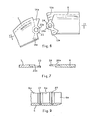
- the air shield according to this invention being made up of two halves hinged together, is able to adapt to the windows of different types of motor vehicles, in which the slope of the fore edge of the window may vary from vehicle to vehicle.
- the horizontal shield portion 6, as shown in figures 5 and 9, is provided with transversal grooves 27, over a pre-established length L, leading off from the rear end of the shield portion 6, for example, over a third or a quarter of its length; said grooves 27 constitute weakened portions which can be broken off, or easily cut with a tool in order to remove, whenever necessary, one or more bands 6a of the shield portion, of a pre-established modular width, and specially designed according to the actual dimensions of the windows of existing motor vehicles; in this way it is possible to obtain an easy neans for adjusting the length of the air shield, especially its horizontal rear portion.
- a rim element 27, shown in the views of figs. 5, 10 and 11, is snapped on, or slipped onto the rear cut end of the horizontal shield portion 6.
- the rim element 27 can be secured in any way, for example, by providing guide means 29a, 29b close to the lower horizontal edge and rear vertical edge respectively.
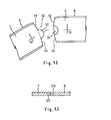
- FIGS 12 and 13 show a different embodiment of the hinge joint 12 between the two shield portions 6 and 7.
- the hinge is achieved as an integral part of the air shield itself by providing, for ex- 'ample, a semicircular protrusion 30 at one end of one shield portion, for example, on the shield portion 7, and a matching semicircular seat 31-at the opposite end of the other shield portion, as shown.
- the rest of the two shield portions correspond exactly to those described previously.
Landscapes
- Engineering & Computer Science (AREA)
- Mechanical Engineering (AREA)
- Window Of Vehicle (AREA)
- Motor Or Generator Frames (AREA)
- Motor Or Generator Cooling System (AREA)
- Cooling, Air Intake And Gas Exhaust, And Fuel Tank Arrangements In Propulsion Units (AREA)
- Lighting Device Outwards From Vehicle And Optical Signal (AREA)
- Vehicle Step Arrangements And Article Storage (AREA)
Priority Applications (1)
| Application Number | Priority Date | Filing Date | Title |
|---|---|---|---|
| AT84115297T ATE26810T1 (de) | 1983-12-21 | 1984-12-12 | Einstellbare entlueftungsleiste fuer kraftfahrzeugfenster. |
Applications Claiming Priority (2)
| Application Number | Priority Date | Filing Date | Title |
|---|---|---|---|
| ITMI1983U23914U IT8323914U1 (it) | 1983-12-21 | 1983-12-21 | Aletta deflettrice con angolazione regolabile, per finestrini di autoveicoli. |
| IT2391483U | 1983-12-21 |
Publications (3)
| Publication Number | Publication Date |
|---|---|
| EP0146884A2 true EP0146884A2 (fr) | 1985-07-03 |
| EP0146884A3 EP0146884A3 (en) | 1985-07-31 |
| EP0146884B1 EP0146884B1 (fr) | 1987-04-29 |
Family
ID=11210848
Family Applications (1)
| Application Number | Title | Priority Date | Filing Date |
|---|---|---|---|
| EP84115297A Expired EP0146884B1 (fr) | 1983-12-21 | 1984-12-12 | Déflecteur réglable pour vitres de véhicles automobiles |
Country Status (5)
| Country | Link |
|---|---|
| EP (1) | EP0146884B1 (fr) |
| AT (1) | ATE26810T1 (fr) |
| DE (1) | DE3463349D1 (fr) |
| ES (1) | ES283573Y (fr) |
| IT (1) | IT8323914U1 (fr) |
Cited By (7)
| Publication number | Priority date | Publication date | Assignee | Title |
|---|---|---|---|---|
| US5673959A (en) * | 1994-11-28 | 1997-10-07 | Padlo; Craig W. | Foldable convertible flexible-roof support |
| US5947546A (en) * | 1996-10-22 | 1999-09-07 | Chrysler Corporation | Apparatus for attaching a soft top to a motor vehicle |
| US5979969A (en) * | 1997-10-22 | 1999-11-09 | Chrysler Corporation | Apparatus for selectively mounting a hard top and a soft top to a motor vehicle |
| US5992917A (en) * | 1996-10-22 | 1999-11-30 | Chrysler Corporation | Top system for a motor vehicle |
| US6036256A (en) * | 1996-10-22 | 2000-03-14 | Chrysler Corporation | Window assembly for a motor vehicle |
| US6073989A (en) * | 1996-10-22 | 2000-06-13 | Daimlerchrysler Corporation | Removable door frame assembly for a motor vehicle |
| US6295713B1 (en) | 1996-10-22 | 2001-10-02 | Chrysler Corporation | Method for attaching a soft top to a motor vehicle body |
Family Cites Families (6)
| Publication number | Priority date | Publication date | Assignee | Title |
|---|---|---|---|---|
| US1942225A (en) * | 1931-11-30 | 1934-01-02 | Packard Motor Car Co | Motor vehicle |
| GB609577A (en) * | 1946-03-18 | 1948-10-04 | Worcester Windshields & Caseme | Improvements relating to ventilation louvres for use in connection with sliding windows of vehicles |
| GB787228A (en) * | 1956-04-06 | 1957-12-04 | William Paul Walcott | Weather shield for use with motor vehicles |
| US3726207A (en) * | 1971-10-18 | 1973-04-10 | S Young | Vehicle air deflector |
| CA1168678A (fr) * | 1978-05-01 | 1984-06-05 | James V. Chabot | Deflecteur d'air a positionnement automatique en raison de la resistance aerodynamique |
| FR2443941A1 (fr) * | 1978-12-11 | 1980-07-11 | Acryl | Deflecteur de portiere pour un vehicule automobile |
-
1983
- 1983-12-21 IT ITMI1983U23914U patent/IT8323914U1/it unknown
-
1984
- 1984-12-12 AT AT84115297T patent/ATE26810T1/de not_active IP Right Cessation
- 1984-12-12 DE DE8484115297T patent/DE3463349D1/de not_active Expired
- 1984-12-12 EP EP84115297A patent/EP0146884B1/fr not_active Expired
- 1984-12-20 ES ES1984283573U patent/ES283573Y/es not_active Expired
Cited By (7)
| Publication number | Priority date | Publication date | Assignee | Title |
|---|---|---|---|---|
| US5673959A (en) * | 1994-11-28 | 1997-10-07 | Padlo; Craig W. | Foldable convertible flexible-roof support |
| US5947546A (en) * | 1996-10-22 | 1999-09-07 | Chrysler Corporation | Apparatus for attaching a soft top to a motor vehicle |
| US5992917A (en) * | 1996-10-22 | 1999-11-30 | Chrysler Corporation | Top system for a motor vehicle |
| US6036256A (en) * | 1996-10-22 | 2000-03-14 | Chrysler Corporation | Window assembly for a motor vehicle |
| US6073989A (en) * | 1996-10-22 | 2000-06-13 | Daimlerchrysler Corporation | Removable door frame assembly for a motor vehicle |
| US6295713B1 (en) | 1996-10-22 | 2001-10-02 | Chrysler Corporation | Method for attaching a soft top to a motor vehicle body |
| US5979969A (en) * | 1997-10-22 | 1999-11-09 | Chrysler Corporation | Apparatus for selectively mounting a hard top and a soft top to a motor vehicle |
Also Published As
| Publication number | Publication date |
|---|---|
| ES283573U (es) | 1985-06-16 |
| DE3463349D1 (en) | 1987-06-04 |
| EP0146884A3 (en) | 1985-07-31 |
| ATE26810T1 (de) | 1987-05-15 |
| IT8323914V0 (it) | 1983-12-21 |
| EP0146884B1 (fr) | 1987-04-29 |
| IT8323914U1 (it) | 1985-06-21 |
| ES283573Y (es) | 1986-04-01 |
Similar Documents
| Publication | Publication Date | Title |
|---|---|---|
| US5072546A (en) | Weather strip for use in automobile | |
| JP2721039B2 (ja) | 車 体 | |
| US5894706A (en) | Molded window door and method | |
| CA1074836A (fr) | Hublot de toit transparent et amovible pour vehicules | |
| US3934383A (en) | Roof vent | |
| KR100580406B1 (ko) | 차량 도어 프레임용 장식용 성형 조립체 | |
| ES2295841T3 (es) | Disposicion de obturacion para obturar y guiar una luna movil de ventanilla, especialmente de un vehiculo de motor. | |
| US5548929A (en) | Window sealing assembly | |
| US6938665B2 (en) | Door | |
| EP0146884B1 (fr) | Déflecteur réglable pour vitres de véhicles automobiles | |
| US5765895A (en) | Door and hood hinge for motor vehicles | |
| US4343504A (en) | All glass rear door assembly for an automotive vehicle | |
| US5586362A (en) | Anti-rubbing block | |
| US5457913A (en) | Hinge mounting for auto ventilation window | |
| GB2261497A (en) | Lamp for motor vehicles | |
| US4062272A (en) | Stationary vent apparatus | |
| EP0382288B1 (fr) | Véhicule, en particulier camping-bus ou caravane | |
| EP0885778B1 (fr) | Profil d'étanchéité d'angle | |
| US5653059A (en) | Housing structure | |
| GB2057038A (en) | Circular pivoting windows | |
| JPH0739138Y2 (ja) | ワイヤハーネスグロメット | |
| GB2302558A (en) | Vehicle window assembly | |
| US2066590A (en) | Vehicle ventilating wing | |
| JPS6010006Y2 (ja) | 車両用ヘッドランプにおける前面レンズの構造 | |
| JPH0297116U (fr) |
Legal Events
| Date | Code | Title | Description |
|---|---|---|---|
| PUAI | Public reference made under article 153(3) epc to a published international application that has entered the european phase |
Free format text: ORIGINAL CODE: 0009012 |
|
| PUAL | Search report despatched |
Free format text: ORIGINAL CODE: 0009013 |
|
| AK | Designated contracting states |
Designated state(s): AT BE CH DE FR GB LI |
|
| AK | Designated contracting states |
Designated state(s): AT BE CH DE FR GB LI |
|
| 17P | Request for examination filed |
Effective date: 19851024 |
|
| 17Q | First examination report despatched |
Effective date: 19860722 |
|
| GRAA | (expected) grant |
Free format text: ORIGINAL CODE: 0009210 |
|
| AK | Designated contracting states |
Kind code of ref document: B1 Designated state(s): AT BE CH DE FR GB LI |
|
| REF | Corresponds to: |
Ref document number: 26810 Country of ref document: AT Date of ref document: 19870515 Kind code of ref document: T |
|
| REF | Corresponds to: |
Ref document number: 3463349 Country of ref document: DE Date of ref document: 19870604 |
|
| ET | Fr: translation filed | ||
| PG25 | Lapsed in a contracting state [announced via postgrant information from national office to epo] |
Ref country code: AT Effective date: 19871212 |
|
| PG25 | Lapsed in a contracting state [announced via postgrant information from national office to epo] |
Ref country code: LI Effective date: 19871231 Ref country code: CH Effective date: 19871231 Ref country code: BE Effective date: 19871231 |
|
| PLBE | No opposition filed within time limit |
Free format text: ORIGINAL CODE: 0009261 |
|
| STAA | Information on the status of an ep patent application or granted ep patent |
Free format text: STATUS: NO OPPOSITION FILED WITHIN TIME LIMIT |
|
| 26N | No opposition filed | ||
| BERE | Be: lapsed |
Owner name: MASI LAMBERTO Effective date: 19871231 |
|
| PG25 | Lapsed in a contracting state [announced via postgrant information from national office to epo] |
Ref country code: FR Free format text: LAPSE BECAUSE OF NON-PAYMENT OF DUE FEES Effective date: 19880831 |
|
| REG | Reference to a national code |
Ref country code: CH Ref legal event code: PL |
|
| PG25 | Lapsed in a contracting state [announced via postgrant information from national office to epo] |
Ref country code: DE Effective date: 19880901 |
|
| REG | Reference to a national code |
Ref country code: FR Ref legal event code: ST |
|
| PG25 | Lapsed in a contracting state [announced via postgrant information from national office to epo] |
Ref country code: GB Effective date: 19881212 |
|
| GBPC | Gb: european patent ceased through non-payment of renewal fee |