EP0146667A2 - Hohlbaustein - Google Patents
Hohlbaustein Download PDFInfo
- Publication number
- EP0146667A2 EP0146667A2 EP19840103422 EP84103422A EP0146667A2 EP 0146667 A2 EP0146667 A2 EP 0146667A2 EP 19840103422 EP19840103422 EP 19840103422 EP 84103422 A EP84103422 A EP 84103422A EP 0146667 A2 EP0146667 A2 EP 0146667A2
- Authority
- EP
- European Patent Office
- Prior art keywords
- hollow
- block according
- support
- hollow block
- web
- Prior art date
- Legal status (The legal status is an assumption and is not a legal conclusion. Google has not performed a legal analysis and makes no representation as to the accuracy of the status listed.)
- Withdrawn
Links
- 230000000295 complement effect Effects 0.000 claims description 4
- 238000003780 insertion Methods 0.000 abstract description 2
- 230000037431 insertion Effects 0.000 abstract description 2
- 238000004519 manufacturing process Methods 0.000 description 8
- 238000010276 construction Methods 0.000 description 4
- 230000002787 reinforcement Effects 0.000 description 4
- 239000004575 stone Substances 0.000 description 3
- 230000003247 decreasing effect Effects 0.000 description 2
- 210000003608 fece Anatomy 0.000 description 2
- 239000011464 hollow brick Substances 0.000 description 2
- 239000010871 livestock manure Substances 0.000 description 2
- 230000015572 biosynthetic process Effects 0.000 description 1
- 238000009414 blockwork Methods 0.000 description 1
- 239000011449 brick Substances 0.000 description 1
- 238000009415 formwork Methods 0.000 description 1
- 239000011796 hollow space material Substances 0.000 description 1
- 230000001771 impaired effect Effects 0.000 description 1
- 239000007788 liquid Substances 0.000 description 1
- 238000000034 method Methods 0.000 description 1
- 239000002002 slurry Substances 0.000 description 1
- 239000007787 solid Substances 0.000 description 1
- 230000007704 transition Effects 0.000 description 1
Images

Classifications
-
- E—FIXED CONSTRUCTIONS
- E04—BUILDING
- E04B—GENERAL BUILDING CONSTRUCTIONS; WALLS, e.g. PARTITIONS; ROOFS; FLOORS; CEILINGS; INSULATION OR OTHER PROTECTION OF BUILDINGS
- E04B2/00—Walls, e.g. partitions, for buildings; Wall construction with regard to insulation; Connections specially adapted to walls
- E04B2/02—Walls, e.g. partitions, for buildings; Wall construction with regard to insulation; Connections specially adapted to walls built-up from layers of building elements
- E04B2/42—Walls having cavities between, as well as in, the elements; Walls of elements each consisting of two or more parts, kept in distance by means of spacers, at least one of the parts having cavities
- E04B2/44—Walls having cavities between, as well as in, the elements; Walls of elements each consisting of two or more parts, kept in distance by means of spacers, at least one of the parts having cavities using elements having specially-designed means for stabilising the position; Spacers for cavity walls
- E04B2/46—Walls having cavities between, as well as in, the elements; Walls of elements each consisting of two or more parts, kept in distance by means of spacers, at least one of the parts having cavities using elements having specially-designed means for stabilising the position; Spacers for cavity walls by interlocking of projections or inserts with indentations, e.g. of tongues, grooves, dovetails
-
- E—FIXED CONSTRUCTIONS
- E04—BUILDING
- E04B—GENERAL BUILDING CONSTRUCTIONS; WALLS, e.g. PARTITIONS; ROOFS; FLOORS; CEILINGS; INSULATION OR OTHER PROTECTION OF BUILDINGS
- E04B2/00—Walls, e.g. partitions, for buildings; Wall construction with regard to insulation; Connections specially adapted to walls
- E04B2/02—Walls, e.g. partitions, for buildings; Wall construction with regard to insulation; Connections specially adapted to walls built-up from layers of building elements
- E04B2/42—Walls having cavities between, as well as in, the elements; Walls of elements each consisting of two or more parts, kept in distance by means of spacers, at least one of the parts having cavities
- E04B2/50—Walls having cavities between, as well as in, the elements; Walls of elements each consisting of two or more parts, kept in distance by means of spacers, at least one of the parts having cavities using elements having a general shape differing from that of a parallelepiped
-
- E—FIXED CONSTRUCTIONS
- E04—BUILDING
- E04B—GENERAL BUILDING CONSTRUCTIONS; WALLS, e.g. PARTITIONS; ROOFS; FLOORS; CEILINGS; INSULATION OR OTHER PROTECTION OF BUILDINGS
- E04B2/00—Walls, e.g. partitions, for buildings; Wall construction with regard to insulation; Connections specially adapted to walls
- E04B2/02—Walls, e.g. partitions, for buildings; Wall construction with regard to insulation; Connections specially adapted to walls built-up from layers of building elements
- E04B2002/0256—Special features of building elements
- E04B2002/0265—Building elements for making arcuate walls
Definitions
- the invention relates to a hollow building block according to the preamble of patent claim 1.
- a hollow block which has the shape of a circular arc cutout.
- different shapes of such hollow building blocks are necessary, which necessitates several stone shapes, so that the manufacture and trade in such hollow building blocks is difficult.
- the curvature of the H is ohlbausteines dimensioned such that the outer surface of the hollow block on is an arc of a circle, the double radius of which corresponds to the diameter of the building. If, however, a circular building of smaller diameter is to be created with such a hollow building block, the individual hollow building blocks are to be provided inclined to one another in the horizontal plane, as a result of which the seams between adjacent hollow building blocks open.
- the invention has for its object to improve a hollow block of the type mentioned in such a way that straight structures and round structures of different diameters can be easily created with one and the same hollow block.
- the hollow building block at least one of the two side walls is extended beyond the one end face and, together with the extended section, forms a guide inner surface for the complementary section of a hollow building block of the same shape.
- the other side wall has a support at its end opposite the extended section, on which a bearing surface of the associated side wall of another hollow building block comes to rest.
- two adjacent hollow building blocks can be provided in any relative position that can be changed by a pivot point, the pivot point preferably being defined in the side wall forming the support and near the support surface.
- Each hollow module is rounded at the end of that side wall, the other end of which represents the inner guide surface, the curvature of the rounded section corresponding to the curvature of the inner guide surface.
- the rounded area of a hollow building block thus lies at least partially within the inner guide surface of the subsequent hollow building block.
- round silos or round structures with a diameter of at least 4 meters, for example also with a diameter of 30 meters, can thus be created when a single stone shape is required, the same hollow block also being able to be used for building straight masonry.
- the design of the hollow building block is advantageously made such that it has a very low weight and enables relatively easy processing even for laypersons.
- Such a hollow building block is used in particular for the production of round silos for holding agricultural manure, liquid manure, but can also be used for the production of other structures that require wholly or partly curved walls.
- any kind of rounded masonry can be erected with a single, identical shape. Up to a predetermined number of degrees at the interface of adjacent hollow building blocks can thus be made without opening joints at the seams which would allow concrete to run out, which is filled into the hollow building blocks.
- vertical recesses are provided in the webs or end faces connecting the two side walls of each hollow module, which enables the use of reinforcements in a horizontal position without the full support of the hollow module being impaired.
- a further embodiment of the hollow module has a closed and an open cavity, the end face of the hollow module having rounded corners or edges in the region of the closed cavity.
- the webs of the hollow building block which run backwards from the side walls are in alignment with the side walls and are provided with curves facing the open cavity, the curvature of which essentially corresponds to the curvature of the rounded edges.
- the basic shape of these hollow building blocks is not fixed in a predetermined direction and can advantageously also be used on site like normal bricks without a predetermined “top” and “bottom”.
- hollow building block round structures with a diameter of, for example, 3 m to for example 35 m in diameter can be created.
- the hollow block is also advantageously suitable for the construction of straight masonry as a result of the extension sections extended from the side walls in alignment with the side walls.
- the essentially straight shape of the hollow building block ensures easy processing and the use of non-round structures.
- bends or radii of various sizes can be reached, the stones interlocking so far that the concrete poured into the cavities of the hollow building blocks cannot flow out.
- the invention creates a hollow building block, which can also be called a molded block or formwork block and is used to create masonry or the like, with its cavities being poured with concrete.
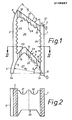
- Fig. 1 shows a plan view of a hollow block according to the invention.
- the hollow block has an essentially square shape and consists of two side walls 1, 2, which are connected to one another by end walls or webs 3, 4.
- the side wall 2 shown in FIG. 1 is extended over the web 4 into a section 5, the inner surface 6 of which is curved in a manner to be described and which represents a guide surface.
- the end of the side wall 2, designated 8 and facing away from the section 5, has a rounding which corresponds in shape to the curvature of the guide surface 6.
- the side wall 1 opposite the side wall 2 has at its one end adjacent to the section 5 a support 10, which preferably has the shape of a semicircular cylindrical pin.
- the other end of this side wall 1 is complementary to the rounding of the support 10, i.e. it is provided with a semicircular or arcuate recess 11 which serves as a bearing surface in the manner to be explained.
- the guide surface 6 lies on the arc of a circle, the center 12 of which is defined in the region of the edge of the side wall 1 having the support 10.
- the radius of the circle, on the arc of which the inner surface 6 lies, is designated R 1 in FIG. 1.
- the center 12 is at the same time preferably the center of a further circle with the radius R 2 , which defines the support 10 in the form of a partial circle or semicircle.
- the center point 12 also represents the center point of the circle which defines the bearing surface in the form of a recess 11 'for the adjacent hollow block. The corresponding center point is indicated in Fig. 1 with 12 '.
- each web 3, 4 is provided with one or more cutouts 14, 15, 16 or 17, 18, 19, which serve to accommodate reinforcements or ring anchors, not shown.
- the webs 3, 4 together with the side walls 1, 2 form a cavity 20, which is formed by semi-circular or semi-oval-like recesses 22 to 25 on the inner surfaces of the side walls 1, 2 and / or webs 3, 4 facing the cavity and thus to reduce the weight each hollow building block can be enlarged.
- the web 4 and the extension section 5 of the side wall 2 define a cavity 27 which is open in contrast to the cavity 20 and in which the one end of a further hollow module of the same shape can be inserted.
- the entire extension section 5 has the shape of a circular arc, the edge 5a of the extension section 5 being symmetrical to the center point 12 with respect to the imaginary center line 28.
- the angle ⁇ 'of the cavity 27 defined by the outwardly facing and the recesses 23 of the outer surface of the web 4 on the one hand and the end edge 5a has a size of 50 ° to 60 ° in the embodiment of the hollow component shown in FIG. 1.
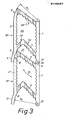
- Fig. 2 shows a sectional view along the line II-II in Fig. 1, from which it can be seen that the web 3 and / or 4 has recesses 30 to 32 at least in the middle of the web lower height than the associated side walls 1, 2nd
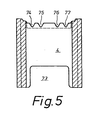
- FIG. 3 is an illustration of two adjacent hollow blocks according to the embodiment of FIG. 1, which are assembled to form a straight masonry. From Fig. 3 it can be seen that the side walls 1, 1 'are aligned, the semi-circular bearing surface 11' is in contact with the support 10. The alignment shown in FIG. 3 with respect to one another can be achieved by appropriate alignment of the two hollow building blocks, designated 30 and 31 in FIG. 3. As can be seen from FIG.
- the hollow module 31 can be rotated by pivoting around the support 10 with its section 8 'further into the cavity designated 27 or further out of the cavity 27 around the point designated 12 as a fulcrum, whereby the bearing surface 11 'slides on the surface of the support 10 on the one hand and the outer surface 8' slides relative to the inner surface 6 on the other hand.
- the length of section 8 'and section 5, in each case in the direction of the imaginary center line 28, makes it possible to determine the angular range within which the two hollow building blocks 30, 31 from the position shown in FIG. 3 can be pivoted relative to one another.
- the swivel range between the hollow modules 30, 31 lying against each other can be increased or decreased.
- the inclination of the web 4 with respect to the side wall 1 can be increased or decreased. It is thus clear that by changing the rotational position of the hollow module 31 around the center point 12 and thus in relation to the hollow module 30, almost any rounding, ie any diameter, can be achieved.
- the resulting cavities are filled with concrete, the hollow space 27, which is closed by the web 3 ′ compared to FIG. 1, also being filled with concrete.
- the cavities are expediently filled with concrete or the like after the hollow blocks have been walled up in dry construction.
- the web 4 consists of two web sections 4a, 4b which are inclined at an angle to one another
- the hollow module can also be designed such that the web 4 is a single, straight web or represents an approximately arcuate or elliptical web.
- the hollow block designated 40 has a "front" web 41, which is referred to below as the end face 41, which according to a preferred embodiment has recesses 17a, 17b, 18, 19 for receiving armaments is provided. These recesses can also be omitted if necessary.
- the hollow block 40 has in essential L ch i s straight extending side walls 1, 2 which pass into rearward extended portions 5, 42nd The encryption l e n e g narrowing sections 5, 42 are in contrast to the embodiment of FIG.
- the two cavities 20 , 27 are separated from one another by a web 4.
- the web 4 preferably has the below with reference to Fig. 5 to be described form, runs but substantially perpendicular to the two side walls 1, 2, as a result, the cavity 20 is essentially a tunnel correspond ch cross-sectional shape, while the cavity 27 has the shape of a U.
- Essential characteristics of the hollow block 40 are respectively the lateral I l of the end face 41 arranged vertical surfaces. Edges 44, 45 and facing to the cavity 27 rounded portions 46, 47. The curvature of the side surfaces 44, 45 * defined by a radius which is drawn from a point on an axial center line 48 point 49, and domestic nerh alb of the cavity 20 is on line 48. The radius is indicated by reference numeral 50 in FIG. 4.
- a region of greater curvature follows, as shown by reference numeral 51, wherein the reference numeral 51 is selected corresponding de radius substantially smaller than the radius corresponding to the reference numerals 50th In this way, a transition from a curvature surface with a small curvature to a curvature with a larger curvature corresponding to the radius 51 to the end face 41 is achieved.
- the surface 44, 45 merges into a curved surface, which is defined by a radius 54 and defines an extension 55, which defines the limit for the pivotability of two building blocks located one behind the other.
- the hollow module 40 is formed symmetrically to the center line 48.
- the radius 54 corresponds approximately to the radius indicated by the reference symbol 51.
- the curvature indicated by reference number 55 also corresponds approximately to the radius 51.
- curvature surfaces are provided which largely correspond to the radius of curvature 50.
- the surfaces 46, 47 result from a radius 58 which is drawn from a point 59 which lies on the line of symmetry 48.
- the distance between the point 59 and the rear end face 60 of the extension sections 5, 42 is denoted by 61 in FIG. 4 and preferably corresponds to the distance 62 which the circle center 49 of the circle 50 maintains relative to a line or plane 65 which is parallel to the end face 41 through the apex line of the substantially U-shaped inner surface 66 of the cavity 20.
- the radius 58 is equal to or slightly larger than the radius 50, which ensures that the curvature of the surfaces 44, 45 is stronger than the correspondingly curved wall sections 46, 47, so that easy insertion and rotation of a subsequent hollow block, not shown, within the curved wall surfaces 46, 47 can be reached at the end of the hollow component shown in FIG. 4.
- FIG. 6 shows two hollow modules 71, 72 arranged one behind the other. From Fig.
- the cavity 27 is closed by the rear hollow module 72. Additional reinforcements, which are not shown in the drawing, can be inserted into the closed cavities 20 and 27 thus formed.
- the angular position of the successive hollow building blocks 71, 72 relative to one another is limited by the step-shaped projections 55 on both sides of each hollow building block. In a further embodiment, not shown, such step-like projections or stops 55 are not provided.
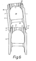
- FIG. 5 shows a sectional view of the hollow building block according to FIG. 4 along the line VV. From Fig. 5 it can be seen that the web 4 does not have to extend over the entire height of the hollow block.
- the web 4 contains a lower recess 73 and on its upper edge a plurality of preferably notch-shaped recesses 74, 75, 76, 77, which correspond to the recesses 17a to 19 on the end face and are provided for inserting reinforcements can.
- the lower recess 73 enables an easy flow of the Ver spallbetons and / or the inclusion of additional A r-m ists emotions.
- the hollow building blocks according to the invention are not only arranged one behind the other in a row according to FIG. 6, but rather in several rows one above the other like conventional building blocks.
- Two hollow blocks, one behind the other, result in a tongue and groove connection, avoiding gaps that prevent the concrete poured into the cavities 20 and 27 from flowing out.
- a plurality of webs 4 can also be formed between the side walls 1, 2.
- the production of a wall with the hollow blocks according to the invention is carried out in such a way that several hollow blocks are arranged in a row one behind the other in such a way that the front end 41 extends into the open cavity 27 of the preceding cavity, the rounded side surfaces 44, 45 on the one hand with the rounded portions 46, 47, on the other hand, are in contact and practically no open seams or joints remain.
- the cavities formed are filled with concrete and the concrete is shaken, so that an optimal solid structure results. Then further, for example a maximum of three dry layers of hollow bricks are placed on the partial masonry and the process is repeated.
- round masonry for example slurry tanks
- slurry tanks can be produced in the simplest way, with only a single form of building blocks being used.
- roundings or rounded side surfaces are provided on its front side in such a way that it can be used in correspondingly rounded inner surfaces on the rear side of a subsequent hollow block, the subsequent hollow block being at a desired angle can be arranged pivoted relative to the former hollow block. Due to the relative pivotability of successive hollow blocks, not only circular, but also masonry of any other shape can be created.
Landscapes
- Engineering & Computer Science (AREA)
- Architecture (AREA)
- Physics & Mathematics (AREA)
- Electromagnetism (AREA)
- Civil Engineering (AREA)
- Structural Engineering (AREA)
- Revetment (AREA)
Applications Claiming Priority (4)
| Application Number | Priority Date | Filing Date | Title |
|---|---|---|---|
| DE3347443 | 1983-12-29 | ||
| DE3347443 | 1983-12-29 | ||
| DE3400810 | 1984-01-12 | ||
| DE3400810 | 1984-01-12 |
Publications (1)
| Publication Number | Publication Date |
|---|---|
| EP0146667A2 true EP0146667A2 (de) | 1985-07-03 |
Family
ID=25816890
Family Applications (1)
| Application Number | Title | Priority Date | Filing Date |
|---|---|---|---|
| EP19840103422 Withdrawn EP0146667A2 (de) | 1983-12-29 | 1984-03-28 | Hohlbaustein |
Country Status (2)
| Country | Link |
|---|---|
| EP (1) | EP0146667A2 (da) |
| DK (1) | DK173384A (da) |
Cited By (2)
| Publication number | Priority date | Publication date | Assignee | Title |
|---|---|---|---|---|
| GB2223519A (en) * | 1988-08-25 | 1990-04-11 | Gahin Dr Salah | Hollow building block with drip nose |
| WO1990015905A3 (de) * | 1989-06-19 | 1991-06-13 | Hilmar Werner | Bausystem aus formsteinen und leichttrag werken |
-
1984
- 1984-03-28 EP EP19840103422 patent/EP0146667A2/de not_active Withdrawn
- 1984-03-30 DK DK173384A patent/DK173384A/da active IP Right Grant
Cited By (3)
| Publication number | Priority date | Publication date | Assignee | Title |
|---|---|---|---|---|
| GB2223519A (en) * | 1988-08-25 | 1990-04-11 | Gahin Dr Salah | Hollow building block with drip nose |
| GB2223519B (en) * | 1988-08-25 | 1992-07-29 | Gahin Dr Salah | Building block |
| WO1990015905A3 (de) * | 1989-06-19 | 1991-06-13 | Hilmar Werner | Bausystem aus formsteinen und leichttrag werken |
Also Published As
| Publication number | Publication date |
|---|---|
| DK173384D0 (da) | 1984-03-30 |
| DK173384A (da) | 1985-06-30 |
Similar Documents
| Publication | Publication Date | Title |
|---|---|---|
| DE3990874C2 (de) | Selbsttragendes, miteinander zu verbindendes Schalungselement zum Gießen von Wandkonstruktionen | |
| DE2553027C2 (de) | Spielbaukasten mit Knoten- und Stabbauteinen | |
| DE1900397A1 (de) | Baustein | |
| CH653079A5 (de) | Wand, zusammengesetzt aus mehreren wandelementen. | |
| EP3867455B1 (de) | Mauerblock | |
| DE29922003U1 (de) | Bauelement aus Kunststein | |
| EP1149207B1 (de) | Palisade | |
| DE9115223U1 (de) | Schlüssel für Zylinderschloß sowie Zylinderschloß | |
| DE3201832A1 (de) | Hohlbaustein und darauf aufgebautes baukastensystem | |
| DE3411479C2 (da) | ||
| DE3400742C2 (de) | Kugelpfanne | |
| EP0146667A2 (de) | Hohlbaustein | |
| DE2018119A1 (da) | ||
| AT1336U1 (de) | Verbindungskonstruktion | |
| EP1809819B1 (de) | Formstein | |
| DE202004011238U1 (de) | Verwahrkasten für Bewehrungsanschlüsse für Betonverbindungen, Bewehrungsanschluß mit einem Verwahrkasten und Betonverbindung | |
| EP0860109A2 (de) | Fertigteile für Bauwerke und Bauwerk hiervon | |
| EP0927792B1 (de) | Pflastersteinelement | |
| DE19623659C2 (de) | Ziegelwand aus mindestens zwei vorgefertigten Ziegelwandelementen | |
| DE69222009T2 (de) | Mit Mörtel ausfüllbarer Verbindungskörper für Bewehrungsstäben | |
| EP4596803A1 (de) | Bauwerk und thermisch isolierendes bauelement | |
| DE29812417U1 (de) | Sockelelement und Sockelsystem | |
| DE20313254U1 (de) | Formstein-System | |
| DE3435061A1 (de) | Verformbarer bogenstein fuer ein bausystem mit schalungs-steckbausteinen aus hartschaum | |
| DE3340648A1 (de) | Bauelement fuer die mantelbetonbauweise |
Legal Events
| Date | Code | Title | Description |
|---|---|---|---|
| PUAI | Public reference made under article 153(3) epc to a published international application that has entered the european phase |
Free format text: ORIGINAL CODE: 0009012 |
|
| AK | Designated contracting states |
Designated state(s): AT BE CH DE FR GB IT LI LU NL SE |
|
| STAA | Information on the status of an ep patent application or granted ep patent |
Free format text: STATUS: THE APPLICATION IS DEEMED TO BE WITHDRAWN |
|
| 18D | Application deemed to be withdrawn |
Effective date: 19861001 |
|
| RIN1 | Information on inventor provided before grant (corrected) |
Inventor name: SIEFKEN, MARTIN |