EP0146496A1 - Continuous conveying device and its application - Google Patents
Continuous conveying device and its application Download PDFInfo
- Publication number
- EP0146496A1 EP0146496A1 EP84810465A EP84810465A EP0146496A1 EP 0146496 A1 EP0146496 A1 EP 0146496A1 EP 84810465 A EP84810465 A EP 84810465A EP 84810465 A EP84810465 A EP 84810465A EP 0146496 A1 EP0146496 A1 EP 0146496A1
- Authority
- EP
- European Patent Office
- Prior art keywords
- drive
- conveyor belt
- transfer roller
- axis
- roller
- Prior art date
- Legal status (The legal status is an assumption and is not a legal conclusion. Google has not performed a legal analysis and makes no representation as to the accuracy of the status listed.)
- Withdrawn
Links
- 230000005540 biological transmission Effects 0.000 claims 2
- 238000004806 packaging method and process Methods 0.000 claims 1
- 230000002950 deficient Effects 0.000 abstract description 2
- 239000011324 bead Substances 0.000 description 1
- 238000005452 bending Methods 0.000 description 1
- 235000015895 biscuits Nutrition 0.000 description 1
- 238000005516 engineering process Methods 0.000 description 1
- 230000007613 environmental effect Effects 0.000 description 1
- 235000013305 food Nutrition 0.000 description 1
- 238000012423 maintenance Methods 0.000 description 1
- 238000011144 upstream manufacturing Methods 0.000 description 1
Images

Classifications
-
- B—PERFORMING OPERATIONS; TRANSPORTING
- B65—CONVEYING; PACKING; STORING; HANDLING THIN OR FILAMENTARY MATERIAL
- B65G—TRANSPORT OR STORAGE DEVICES, e.g. CONVEYORS FOR LOADING OR TIPPING, SHOP CONVEYOR SYSTEMS OR PNEUMATIC TUBE CONVEYORS
- B65G21/00—Supporting or protective framework or housings for endless load-carriers or traction elements of belt or chain conveyors
- B65G21/02—Supporting or protective framework or housings for endless load-carriers or traction elements of belt or chain conveyors consisting essentially of struts, ties, or like structural elements
- B65G21/06—Supporting or protective framework or housings for endless load-carriers or traction elements of belt or chain conveyors consisting essentially of struts, ties, or like structural elements constructed to facilitate rapid assembly or dismantling
Definitions
- the present invention relates to a continuous conveying device according to the preamble of independent claim 1, and to a use thereof according to claim 5.
- Such continuous conveyors in particular with a conveyor belt or belt, are known and are used in many areas of technology today. All these devices have in common that an infinite conveyor belt is guided over deflection rollers and is coupled to a drive. Such a drive can act directly on a deflection roller. Two of the deflection rollers, namely a downstream roller and an upstream roller, determine the upper run of the continuous conveyor, on which the goods are then transported.
- a disadvantage of such devices is that the conveyor belt sometimes. As a result of the bending stresses and also as a result of environmental influences, it can often show damage after a short time and must be replaced.
- 1 and 2 consists of a machine frame 10 and a cassette 20. Of the machine frame 10, only those necessary for operation are provided Parts shown, such as frame plate 11, drive shaft 12 with rigidly attached friction wheel 13 and transfer roller 14.
- This transfer roller 14 is rotatably mounted on a shaft 16 with guide element 17 and this guide element 17 is in turn guided and stands in a slot-shaped recess 18 for performing a translational movement under the bias by a coil spring 19. This arrangement is clearly shown in Fig. 2.
- the cassette 20 has a housing 21 which consists of two parallel housing plates 22, 23 and an upper guide table 22 ', with upper deflection rollers 24, 25 of a tensioning roller 26 and a drive roller 27 rotatably mounted between the housing plates 22, 23.
- the conveyor belt 28 wraps around all four rollers 24, 25, 26 and 27.
- the upper run 29 is stretched between the two upper deflection rollers 24, 25.
- Machine frame 10 and cassette 20 are provided with interlocking holding parts, by means of which the mutual position is precisely determined.
- the machine frame 10 has two outer bearing surfaces 30, 31 and side walls 32, 33 in the direction of flow and the cassette 20 is provided with support surfaces 34, 35 for bearing on the outer bearing surfaces.
- the exact mutual position is determined by means of pins 36 and guide openings 37.
- the pins 36 can additionally have locking notches or beads and locking springs can be provided in the guide openings 37. Since these holding elements are well known in the art, no further description has been given.
- the drive roller 27 presses against the transfer roller 14, which thus exerts a contact pressure determined by the spring 19 both against the friction wheel 13 and against the drive roller 27.
- the deflecting rollers 24, 25 therefore do not have to have any specific dimensions in order to achieve a specific transport speed because the drive is arranged elsewhere. Rollers with a smaller diameter can advantageously be used.
- defective conveyor belts 29 can be replaced by untrained personnel without any assembly effort and without significant interruption of operation, without having to pay attention to the exact fit of ball bearings or other bearing or tensioning elements.
- the maintenance work can then be carried out by qualified personnel or by the manufacturer of the transport system with care and without haste.
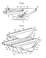
- Fig. 3 shows a universally usable cassette 40 with longitudinally variable guide table 41.
- the same parts as in Fig. 1 and 2 are denoted the same.
- the conveyor table 22 'shown in one piece in FIG. 2 consists of two partial tables 41, 42.
- Each of these partial tables 41, 42 is mounted on a rail 43, 44 so as to be longitudinally displaceable.
- the holder consists essentially of a support 45, 46 and a clamping part 47, 48.
- the rail 43 is fixed to the frame 40 on the cassette 40
- the rail 44 is on a carrier guide 49 inclined relative to the perpendicular to the cassette 40
- the mit.dem subtable 42 is integrally connected.
- the clamping part 48 By adjusting the clamping part 48, the sub-table 42 can then be moved toward or away from the sub-table 41 and held there.
- the carrier guide 49 can also be arranged displaceably together with the holder 50, in order thereby to be able to pivot the sub-table 42 away.
- a whole number of transport routes can be preset, or with actuators, such as hydraulic or pneumatic cylinders, the sub-table 42 can be made adjustable in height and distance.
- additional deflection rollers 51, 53 are provided, around which the conveyor belt 28 is also wrapped.
- the length of the upper run 29 of the conveyor belt 28 can be changed by moving the deflecting rollers 24, 51 together and, in addition, a lower run 52 can be pivoted, as arrows A and B show.
- the two lower deflection rollers 26, 53 are arranged on an additional guide part 54, which is accordingly tiltably supported, for example by the deflection roller 27 being arranged in a stationary manner, and the guide part 54 according to the arrangement in FIG. 3 with carrier guide 49 and holder 50 is adjustable in height.
- conveying equipment can also be combined according to FIG. 5.
- individual or groups of conveying equipment could also be arranged at an angle to one another if conveying lines from several delivery points or to several acceptance points are to be provided.
Landscapes
- Engineering & Computer Science (AREA)
- Mechanical Engineering (AREA)
- Structure Of Belt Conveyors (AREA)
Abstract
Description
Die vorliegende Erfindung betrifft eine Stetigfördervorrichtung gemäss dem Oberbegriff des unabhängigen Patentanspruchs 1, sowie eine Verwendung derselben gemäss Patentanspruch 5.The present invention relates to a continuous conveying device according to the preamble of independent claim 1, and to a use thereof according to claim 5.
Solche Stetigfördervorrichtungen, insbesondere mit einem Transportgurt oder -Band sind bekannt und werden heute in vielen Bereichen der Technik verwendet. Allen diesen Vorrichtungen ist gemeinsam, dass ein unendlicher Transportgurt über Umlenkrollen geführt und mit einem Antrieb gekoppelt ist. Ein solcher Antrieb kann direkt auf eine Umlenkrolle einwirken. Zwei der Umlenkrollen, nämlich eine stromabwärtige und eine stromaufwärtige Rolle bestimmen den oberen Trum des Stetigförderers,auf dem dann das Gut transportiert wird.Such continuous conveyors, in particular with a conveyor belt or belt, are known and are used in many areas of technology today. All these devices have in common that an infinite conveyor belt is guided over deflection rollers and is coupled to a drive. Such a drive can act directly on a deflection roller. Two of the deflection rollers, namely a downstream roller and an upstream roller, determine the upper run of the continuous conveyor, on which the goods are then transported.
Nachteilig an solchen Vorrichtungen ist, dass der Transportgurt z.T. infolge der Biegebeanspruchungen und auch infolge von Umwelteinflüssen oft schon nach kurzer Zeit Beschädigungen aufweisen kann und ersetzt werden muss.A disadvantage of such devices is that the conveyor belt sometimes. As a result of the bending stresses and also as a result of environmental influences, it can often show damage after a short time and must be replaced.
In der EP-A 47 837 wurde dieses Problem schon aufgedeckt und es wurde dazu eine Lösung vorgeschlagen, wobei der Antrieb der einen Umlenkrolle nicht mit fester Verbindung sondern durch Friktion erfolgen soll. Damit ist es möglich, die Umlenkrollen mit dem Fördergurtzusammen herauszunehmen und den alten Fördergurt durch einen neuen Fördergurt zu ersetzen. Die Umlenkrollen sind mittels Kugellager am Gehäuse gelagert. Es ist aber bekannt, dass solche Fördermittel in Betrieben verwendet werden, in denen keine Angestellten mit Ausbildung als Mechaniker beschäftigt werden, wie beispielsweise in Biskuitfabriken oder anderen Betrieben der Lebensmittelindustrie, und wenn dann Kugellager ausgebaut und wieder eingebaut werden müssen, kann dies schon zu erheblichen Schwierigkeiten beim Betrieb führen.This problem has already been disclosed in EP-
Es ist daher eine Aufgabe der Erfindung, eine Stetigfördervorrichtung zu schaffen, bei der ein Auswechseln des Fördergurtes von jeglichem Personal ohne besondere Ausbildung vorgenommen werden kann.It is therefore an object of the invention to provide a continuous conveyor device in which the conveyor belt can be replaced by any personnel without special training.
Erfindungsgemäss wird dies durch die Merkmale im kennzeichnenden Teil des unabhängigen Patentanspruchs 1 erreicht. Eine besonders vorteilhafte Verwendung dieses Stetigförderers ist im Patentanspruch 5 gekennzeichnet.According to the invention this is achieved by the features in the characterizing part of independent claim 1. A particularly advantageous use of this continuous conveyor is characterized in claim 5.
Ausführungsbeispiele der Erfindung werden nachfolgend anhand der Zeichnung erläutert. Es zeigen:
- Fig. 1 eine perspektivische Darstellung eines Stetiförderers nach der Erfindung,
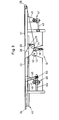
- Fig. 2 eine Schnittansicht eines Stetigförderers gemäss Fig. 1 in grösserem Massstab zur Erläuterung des Prinzips,
- Fig. 3 eine schematische Darstellung einer zweiten Ausführungsform,
- Fig. 4 eine schematische Darstellung einer dritten Ausführungsform, und
- Fig. 5 eine perspektivische Ansicht einer Anordnung mit drei Stetigförderern, von denen einer herausgehoben ist.
- 1 is a perspective view of a continuous conveyor according to the invention,
- 2 is a sectional view of a continuous conveyor according to FIG. 1 on a larger scale to explain the principle,
- 3 shows a schematic illustration of a second embodiment,
- Fig. 4 is a schematic representation of a third embodiment, and
- Fig. 5 is a perspective view of an arrangement with three continuous conveyors, one of which is lifted out.
Die Stetigfördervorrichtung gemäss Fig. 1 und 2 besteht aus einem Maschinengestell 10 und einer Kassette 20. Vom Maschinengestell 10 sind nur die für den Betrieb notwendigen Teile eingezeichnet, wie Gestellplatte 11, Antriebswelle 12 mit starr befestigtem Reibrad 13 sowie Uebertragerwalze 14. Diese Uebertragerwalze 14 ist auf einer Welle 16 mit Führungselement 17 drehbar gelagert und dieses Führungselement 17 ist seinerseits in einer schlitzförmigen Ausnehmung 18 zur Ausführung einer translatorischen Bewegung geführt und steht unter der Vorspannung durch eine Schraubenfeder 19. Diese Anordnung ist in Fig. 2 deutlich dargestellt.1 and 2 consists of a
Die Kassette 20 weist ein Gehäuse 21 auf, das aus zwei parallelen Gehäuseplatten 22, 23 und oberem Führungstisch 22', mit zwischen den Gehäuseplatten 22, 23 drehbar gelagerten oberen Umlenkwalzen 24, 25 einer Spannwalze 26 und einer Antriebswalze 27 besteht. Der Fördergurt 28 umschlingt sämtliche vier Walzen 24, 25, 26 und 27. Der obere Trum 29 ist zwischen den beiden oberen Umlenkwalzen 24, 25 gespannt.The
Maschinengestell 10 und Kassette 20 sind mit ineinander eingreifenden Haltepartien versehen, durch die die gegenseitige Lage genau bestimmt ist. Demgemäss hat das Maschinengestell 10 in Stromrichtung zwei äussere Auflageflächen 30, 31 und Seitenwangen 32, 33 und die Kassette 20 ist mit Stützflächen 34, 35 zur Auflage auf den äusseren Auflageflächen versehen. Mittels Stifte 36 und Führungsöffnungen 37 wird die genaue gegenseitige Lage bestimmt. Die Stifte 36 können noch zusätzlich Rastkerben oder -Wülste aufweisen und bei den Führungsöffnungen 37 können Rastfedern vorgesehen sein. Da diese Halteelemente in der Technik gut bekannt sind, wurde auf eine weitergehende Beschreibung verzichtet.
Im eingesetzten Zustand der Kassette 20 in das Maschinengestell 10 drückt die Antriebswalze 27 gegen die Uebertragerwalze 14, die damit einen durch die Feder 19 bestimmten Anpressdruck sowohl gegen das Reibrad 13 als auch gegen die Antriebswalze 27 ausübt. Die Umlenkwalzen 24, 25 müssen somit keine bestimmten Abmessungen für die Erzielung einer bestimmten Transportgeschwindigkeit aufweisen, weil der Antrieb anderweitig angeordnet ist. Vorteilhafterweise können Walzen mit kleinerem Durchmesser eingesetzt werden.When the
Auf diese Weise können defekte Fördergurte 29 ohne jeglichen Montageaufwand und ohne wesentlichen Betriebsunterbruch durch ungeschultes Personal ausgewechselt werden, ohne dass auf den genauen Sitz von Kugellagern oder sonstigen Lager- oder Spannelementen geachtet werden muss. Die Wartungsarbeit kann dann ihrerseits durch qualifiziertes Personal oder durch den Hersteller der Transportanlage mit aller Sorgfalt und ohne Hast ausgeführt werden.In this way,
Fig. 3 zeigt eine universell verwendbare Kassette 40 mit längsveränderbarem Führungstisch 41. Gleiche Teile wie in Fig. 1 und 2 sind gleich bezeichnet.Fig. 3 shows a universally
Vom Maschinengestell 10 sind hier lediglich das Reibrad 13 mit zugehöriger Antriebswelle 1,2 und die Uebertragerwalze 14 mit Federelement 19 dargestellt. Von der Kassette 40 sind die beiden oberen Umlenkwalzen 24, 25, die Antriebswalze 27 und die Spannwalze 26 mit dem Fördergurt 28 dargestellt.From the
Der in Fig. 2 einstückig dargestellte Fördertisch 22' besteht gemäss dieser Ausführungsform aus zwei Teiltischen 41, 42. Jeder dieser Teiltische 41, 42 ist auf einer Schiene 43, 44 längsverschieblich gehaltert. Die Halterung besteht im wesentlichen aus einer Stütze 45, 46 und einem Klemmteil 47, 48. Während beispielsweise die Schiene 43 gestellfest an der Kassette 40 befestigt ist, ist die Schiene 44 an einer gegenüber der Senkrechten geneigt an der Kassette 40 gehalterten Trägerführung 49, die mit.dem Teiltisch 42 einstückig verbunden ist, befestigt. Durch Einstellung des Klemmteils 48 kann dann der Teiltisch 42 zum Teiltisch 41 hin- oder von diesem wegbewegt und gehaltert werden.According to this embodiment, the conveyor table 22 'shown in one piece in FIG. 2 consists of two partial tables 41, 42. Each of these partial tables 41, 42 is mounted on a
Die Trägerführung 49 kann zusammen mit der Halterung 50 ebenfalls verschiebbar angeordnet werden, um dadurch den Teiltisch 42 abschwenken zu können. Mit einer derartigen Anordnung lassen sich eine ganze Anzahl Transportwege voreinstellen, oder mit Stellorganen, wie hydraulische oder pneumatische Zylinder kann der Teiltisch 42 in der Höhe und im Abstand verstellbar ausgebildet werden.The
In der Anordnung gemäss Fig. 4 sind zu den oberen Umlenkwalzen 24, 25 für den Fördergurt 28 noch zusätzliche Umlenkwalzen 51,53 vorhanden, um die der Fördergurt 28 ebenfalls geschlungen ist. Damit kann beispielsweise der obere Trum 29 des Fördergurtes 28 in der Länge verändert werden, indem die Umlenkwalzen 24, 51 gemeinsam bewegt werden und zusätzlich kann ein unterer Trum 52 geschwenkt werden, wie die Pfeile A und B zeigen. Die beiden unteren Umlenkwalzen 26, 53 sind zu diesem Zweck auf einem zusätzlichen Führungsteil 54 angeordnet , der dementsprechend kippbar gelagert ist, indem beispielsweise die Umlenkwalze 27 ortsfest angeordnet ist, und das Führungsteil 54 gemäss der Anordnung in Fig. 3 mit Trägerführung 49 und Halterung 50 höhenverstellbar ausgebildet ist.In the arrangement according to FIG. 4, in addition to the
Es lassen sich auch mehrere Förderausrüstungen kombinieren gemäss Fig. 5. Zusätzlich könnten auch einzelne oder Gruppen von Förderausrüstungen abgewinkelt zueinander angeordnet sein, wenn Förderstrassen aus mehreren Abgabestellen oder zu mehreren Annahmestellen vorzusehen sind. Durch Zwischenschaltung von bekannten Gleichgang-Gelenken in die Wellenabschnitte 12 zwischen den einzelnen Förderausrüstungen kann der Gleichlauf aller Fördergurte gewährleistet werden.Several conveying equipment can also be combined according to FIG. 5. In addition, individual or groups of conveying equipment could also be arranged at an angle to one another if conveying lines from several delivery points or to several acceptance points are to be provided. Through the interposition of known constant velocity joints in the
Claims (6)
Applications Claiming Priority (2)
| Application Number | Priority Date | Filing Date | Title |
|---|---|---|---|
| CH631083 | 1983-11-24 | ||
| CH6310/83 | 1983-11-24 |
Publications (1)
| Publication Number | Publication Date |
|---|---|
| EP0146496A1 true EP0146496A1 (en) | 1985-06-26 |
Family
ID=4307524
Family Applications (1)
| Application Number | Title | Priority Date | Filing Date |
|---|---|---|---|
| EP84810465A Withdrawn EP0146496A1 (en) | 1983-11-24 | 1984-09-24 | Continuous conveying device and its application |
Country Status (3)
| Country | Link |
|---|---|
| EP (1) | EP0146496A1 (en) |
| JP (1) | JPS60132812A (en) |
| BR (1) | BR8405739A (en) |
Cited By (7)
| Publication number | Priority date | Publication date | Assignee | Title |
|---|---|---|---|---|
| GB2234725A (en) * | 1989-08-04 | 1991-02-13 | British Res Agricult Eng | Multi-section conveyor assembly |
| WO1997008084A1 (en) * | 1995-08-24 | 1997-03-06 | Testamatic Limited | Conveyor and converger incorporating a conveyor |
| US6959803B1 (en) | 2002-12-18 | 2005-11-01 | Span Tech Llc | Self-tensioning conveyor |
| CN105540146A (en) * | 2016-01-28 | 2016-05-04 | 张丰 | Modularized speed-fold chain conveyor belt |
| US9399555B2 (en) | 2012-10-30 | 2016-07-26 | Tomra Systems Asa | Conveyor module docking system for a reverse vending machine |
| US20210032042A1 (en) * | 2019-08-01 | 2021-02-04 | Intelligrated Headquarters, Llc | Multi-belt conveyor system with removable cartridges |
| WO2023011691A1 (en) * | 2021-08-06 | 2023-02-09 | Wipotec Gmbh | Conveying device with transport cassette |
Families Citing this family (6)
| Publication number | Priority date | Publication date | Assignee | Title |
|---|---|---|---|---|
| JPS62196211A (en) * | 1986-02-20 | 1987-08-29 | Hitachi Ltd | Conveyor |
| JPH066099Y2 (en) * | 1986-08-08 | 1994-02-16 | 株式会社石田衡器製作所 | Product weight determination device |
| JPH0447148Y2 (en) * | 1987-03-05 | 1992-11-06 | ||
| JPH031115U (en) * | 1989-05-25 | 1991-01-08 | ||
| JPH0524652Y2 (en) * | 1989-11-30 | 1993-06-23 | ||
| JP3188836B2 (en) * | 1995-08-02 | 2001-07-16 | 三機工業株式会社 | Belt conveyor drive |
Citations (2)
| Publication number | Priority date | Publication date | Assignee | Title |
|---|---|---|---|---|
| DE2161366B2 (en) * | 1970-12-11 | 1973-10-25 | Societe Des Aciers Fins De L'est, Boulogne-Billancourt, Seine (Frankreich) | Chain conveyor with a central base frame carrying a motor gear unit |
| EP0047837A2 (en) * | 1980-09-12 | 1982-03-24 | Robert Bosch Gmbh | Drive for belt conveyors |
-
1984
- 1984-09-24 EP EP84810465A patent/EP0146496A1/en not_active Withdrawn
- 1984-11-09 BR BR8405739A patent/BR8405739A/en unknown
- 1984-11-20 JP JP24357584A patent/JPS60132812A/en active Pending
Patent Citations (2)
| Publication number | Priority date | Publication date | Assignee | Title |
|---|---|---|---|---|
| DE2161366B2 (en) * | 1970-12-11 | 1973-10-25 | Societe Des Aciers Fins De L'est, Boulogne-Billancourt, Seine (Frankreich) | Chain conveyor with a central base frame carrying a motor gear unit |
| EP0047837A2 (en) * | 1980-09-12 | 1982-03-24 | Robert Bosch Gmbh | Drive for belt conveyors |
Cited By (14)
| Publication number | Priority date | Publication date | Assignee | Title |
|---|---|---|---|---|
| GB2234725A (en) * | 1989-08-04 | 1991-02-13 | British Res Agricult Eng | Multi-section conveyor assembly |
| WO1997008084A1 (en) * | 1995-08-24 | 1997-03-06 | Testamatic Limited | Conveyor and converger incorporating a conveyor |
| US6105756A (en) * | 1995-08-24 | 2000-08-22 | Testamatic Limited | Conveyor and converger incorporating a conveyor |
| US6959803B1 (en) | 2002-12-18 | 2005-11-01 | Span Tech Llc | Self-tensioning conveyor |
| US7308979B1 (en) | 2002-12-18 | 2007-12-18 | Span Tech Llc | Self-tensioning conveyor with slave drive |
| US9399555B2 (en) | 2012-10-30 | 2016-07-26 | Tomra Systems Asa | Conveyor module docking system for a reverse vending machine |
| EP2914518B1 (en) * | 2012-10-30 | 2019-02-06 | Tomra Systems ASA | Conveyor module docking system for a reverse vending machine |
| EP3514083A1 (en) * | 2012-10-30 | 2019-07-24 | Tomra Systems ASA | Conveyor module docking system for a reverse vending machine |
| CN105540146A (en) * | 2016-01-28 | 2016-05-04 | 张丰 | Modularized speed-fold chain conveyor belt |
| CN105540146B (en) * | 2016-01-28 | 2017-09-19 | 张丰 | A kind of modularization double-speed chain conveyer belt |
| US20210032042A1 (en) * | 2019-08-01 | 2021-02-04 | Intelligrated Headquarters, Llc | Multi-belt conveyor system with removable cartridges |
| US10988319B2 (en) * | 2019-08-01 | 2021-04-27 | Intelligrated Headquarters, Llc | Multi-belt conveyor system with removable cartridges |
| US11584591B2 (en) | 2019-08-01 | 2023-02-21 | Intelligrated Headquarters, Llc | Multi-belt conveyor system with removable cartridges |
| WO2023011691A1 (en) * | 2021-08-06 | 2023-02-09 | Wipotec Gmbh | Conveying device with transport cassette |
Also Published As
| Publication number | Publication date |
|---|---|
| BR8405739A (en) | 1985-09-17 |
| JPS60132812A (en) | 1985-07-15 |
Similar Documents
| Publication | Publication Date | Title |
|---|---|---|
| DE3432548C2 (en) | Guide device for roller bars in a continuously operating press | |
| EP0438109A2 (en) | Device for cutting frozen food blocks | |
| DE2142117C3 (en) | Cutting device for cutting moving webs in their longitudinal direction into several narrower webs | |
| EP0146496A1 (en) | Continuous conveying device and its application | |
| WO1987004412A1 (en) | Conveyor for workpieces | |
| DE3928454A1 (en) | CLOCK AND TRANSPORT DEVICE | |
| DE4006312A1 (en) | MANUFACTURING SYSTEM FOR MACHINING AND ASSEMBLING COMPONENTS | |
| EP0103122B1 (en) | Double belt press | |
| DE69202389T3 (en) | Upsetting system. | |
| DE69906749T9 (en) | DEVICE FOR TRANSPORTING AND MANIPULATING A MATERIAL RAIL | |
| EP1075943A1 (en) | Printing device | |
| DE3113399A1 (en) | Aligning device for the edges of an imbricated stream consisting of folded products | |
| DE69020503T2 (en) | Plant for feeding from a web. | |
| DE69734789T2 (en) | yarn traverse | |
| DE4422288B4 (en) | Roller positioner for an endless belt press | |
| DE2617562C3 (en) | Clamping bearing for at least one axis used to guide movable parts | |
| DE2560661C2 (en) | ||
| EP0326518B1 (en) | Conveying device comprising belts for forwarding a stream of flat products | |
| DE2504350A1 (en) | Sheet transporter table feeder - has rollers running on support engaging in inclined bearings in their ends | |
| DE3215700A1 (en) | Manipulating device, in particular for fitting, unloading and transporting workpieces | |
| DE2541542C3 (en) | Drive system for the joint drive of shafts arranged in series | |
| DE1935438C3 (en) | Device for bringing together and unifying plastic material webs in a gap between rotating rollers | |
| DE1611362C3 (en) | Alignment table for conveying and simultaneously aligning sheets of paper, cardboard or the like | |
| EP0714770A1 (en) | Device for conveying paper | |
| DE19535345A1 (en) | Drive unit for endless conveyor belt |
Legal Events
| Date | Code | Title | Description |
|---|---|---|---|
| PUAI | Public reference made under article 153(3) epc to a published international application that has entered the european phase |
Free format text: ORIGINAL CODE: 0009012 |
|
| AK | Designated contracting states |
Designated state(s): DE FR GB IT NL |
|
| 17P | Request for examination filed |
Effective date: 19851218 |
|
| R17P | Request for examination filed (corrected) |
Effective date: 19851218 |
|
| 17Q | First examination report despatched |
Effective date: 19860723 |
|
| STAA | Information on the status of an ep patent application or granted ep patent |
Free format text: STATUS: THE APPLICATION IS DEEMED TO BE WITHDRAWN |
|
| 18D | Application deemed to be withdrawn |
Effective date: 19861203 |
|
| RIN1 | Information on inventor provided before grant (corrected) |
Inventor name: NEUNKIRCHNER, ALFRED |