EP0146493A2 - Method for bonding ceramics and metals - Google Patents
Method for bonding ceramics and metals Download PDFInfo
- Publication number
- EP0146493A2 EP0146493A2 EP84730140A EP84730140A EP0146493A2 EP 0146493 A2 EP0146493 A2 EP 0146493A2 EP 84730140 A EP84730140 A EP 84730140A EP 84730140 A EP84730140 A EP 84730140A EP 0146493 A2 EP0146493 A2 EP 0146493A2
- Authority
- EP
- European Patent Office
- Prior art keywords
- insert material
- metal
- ceramic
- sic
- bonding
- Prior art date
- Legal status (The legal status is an assumption and is not a legal conclusion. Google has not performed a legal analysis and makes no representation as to the accuracy of the status listed.)
- Withdrawn
Links
Images
Classifications
-
- C—CHEMISTRY; METALLURGY
- C04—CEMENTS; CONCRETE; ARTIFICIAL STONE; CERAMICS; REFRACTORIES
- C04B—LIME, MAGNESIA; SLAG; CEMENTS; COMPOSITIONS THEREOF, e.g. MORTARS, CONCRETE OR LIKE BUILDING MATERIALS; ARTIFICIAL STONE; CERAMICS; REFRACTORIES; TREATMENT OF NATURAL STONE
- C04B37/00—Joining burned ceramic articles with other burned ceramic articles or other articles by heating
- C04B37/02—Joining burned ceramic articles with other burned ceramic articles or other articles by heating with metallic articles
- C04B37/023—Joining burned ceramic articles with other burned ceramic articles or other articles by heating with metallic articles characterised by the interlayer used
- C04B37/026—Joining burned ceramic articles with other burned ceramic articles or other articles by heating with metallic articles characterised by the interlayer used consisting of metals or metal salts
-
- C—CHEMISTRY; METALLURGY
- C04—CEMENTS; CONCRETE; ARTIFICIAL STONE; CERAMICS; REFRACTORIES
- C04B—LIME, MAGNESIA; SLAG; CEMENTS; COMPOSITIONS THEREOF, e.g. MORTARS, CONCRETE OR LIKE BUILDING MATERIALS; ARTIFICIAL STONE; CERAMICS; REFRACTORIES; TREATMENT OF NATURAL STONE
- C04B35/00—Shaped ceramic products characterised by their composition; Ceramics compositions; Processing powders of inorganic compounds preparatory to the manufacturing of ceramic products
- C04B35/622—Forming processes; Processing powders of inorganic compounds preparatory to the manufacturing of ceramic products
- C04B35/64—Burning or sintering processes
- C04B35/645—Pressure sintering
- C04B35/6455—Hot isostatic pressing
-
- C—CHEMISTRY; METALLURGY
- C04—CEMENTS; CONCRETE; ARTIFICIAL STONE; CERAMICS; REFRACTORIES
- C04B—LIME, MAGNESIA; SLAG; CEMENTS; COMPOSITIONS THEREOF, e.g. MORTARS, CONCRETE OR LIKE BUILDING MATERIALS; ARTIFICIAL STONE; CERAMICS; REFRACTORIES; TREATMENT OF NATURAL STONE
- C04B2237/00—Aspects relating to ceramic laminates or to joining of ceramic articles with other articles by heating
- C04B2237/02—Aspects relating to interlayers, e.g. used to join ceramic articles with other articles by heating
- C04B2237/12—Metallic interlayers
- C04B2237/123—Metallic interlayers based on iron group metals, e.g. steel
-
- C—CHEMISTRY; METALLURGY
- C04—CEMENTS; CONCRETE; ARTIFICIAL STONE; CERAMICS; REFRACTORIES
- C04B—LIME, MAGNESIA; SLAG; CEMENTS; COMPOSITIONS THEREOF, e.g. MORTARS, CONCRETE OR LIKE BUILDING MATERIALS; ARTIFICIAL STONE; CERAMICS; REFRACTORIES; TREATMENT OF NATURAL STONE
- C04B2237/00—Aspects relating to ceramic laminates or to joining of ceramic articles with other articles by heating
- C04B2237/02—Aspects relating to interlayers, e.g. used to join ceramic articles with other articles by heating
- C04B2237/12—Metallic interlayers
- C04B2237/124—Metallic interlayers based on copper
-
- C—CHEMISTRY; METALLURGY
- C04—CEMENTS; CONCRETE; ARTIFICIAL STONE; CERAMICS; REFRACTORIES
- C04B—LIME, MAGNESIA; SLAG; CEMENTS; COMPOSITIONS THEREOF, e.g. MORTARS, CONCRETE OR LIKE BUILDING MATERIALS; ARTIFICIAL STONE; CERAMICS; REFRACTORIES; TREATMENT OF NATURAL STONE
- C04B2237/00—Aspects relating to ceramic laminates or to joining of ceramic articles with other articles by heating
- C04B2237/02—Aspects relating to interlayers, e.g. used to join ceramic articles with other articles by heating
- C04B2237/12—Metallic interlayers
- C04B2237/125—Metallic interlayers based on noble metals, e.g. silver
-
- C—CHEMISTRY; METALLURGY
- C04—CEMENTS; CONCRETE; ARTIFICIAL STONE; CERAMICS; REFRACTORIES
- C04B—LIME, MAGNESIA; SLAG; CEMENTS; COMPOSITIONS THEREOF, e.g. MORTARS, CONCRETE OR LIKE BUILDING MATERIALS; ARTIFICIAL STONE; CERAMICS; REFRACTORIES; TREATMENT OF NATURAL STONE
- C04B2237/00—Aspects relating to ceramic laminates or to joining of ceramic articles with other articles by heating
- C04B2237/02—Aspects relating to interlayers, e.g. used to join ceramic articles with other articles by heating
- C04B2237/12—Metallic interlayers
- C04B2237/126—Metallic interlayers wherein the active component for bonding is not the largest fraction of the interlayer
-
- C—CHEMISTRY; METALLURGY
- C04—CEMENTS; CONCRETE; ARTIFICIAL STONE; CERAMICS; REFRACTORIES
- C04B—LIME, MAGNESIA; SLAG; CEMENTS; COMPOSITIONS THEREOF, e.g. MORTARS, CONCRETE OR LIKE BUILDING MATERIALS; ARTIFICIAL STONE; CERAMICS; REFRACTORIES; TREATMENT OF NATURAL STONE
- C04B2237/00—Aspects relating to ceramic laminates or to joining of ceramic articles with other articles by heating
- C04B2237/30—Composition of layers of ceramic laminates or of ceramic or metallic articles to be joined by heating, e.g. Si substrates
- C04B2237/32—Ceramic
- C04B2237/36—Non-oxidic
- C04B2237/365—Silicon carbide
-
- C—CHEMISTRY; METALLURGY
- C04—CEMENTS; CONCRETE; ARTIFICIAL STONE; CERAMICS; REFRACTORIES
- C04B—LIME, MAGNESIA; SLAG; CEMENTS; COMPOSITIONS THEREOF, e.g. MORTARS, CONCRETE OR LIKE BUILDING MATERIALS; ARTIFICIAL STONE; CERAMICS; REFRACTORIES; TREATMENT OF NATURAL STONE
- C04B2237/00—Aspects relating to ceramic laminates or to joining of ceramic articles with other articles by heating
- C04B2237/30—Composition of layers of ceramic laminates or of ceramic or metallic articles to be joined by heating, e.g. Si substrates
- C04B2237/32—Ceramic
- C04B2237/36—Non-oxidic
- C04B2237/368—Silicon nitride
-
- C—CHEMISTRY; METALLURGY
- C04—CEMENTS; CONCRETE; ARTIFICIAL STONE; CERAMICS; REFRACTORIES
- C04B—LIME, MAGNESIA; SLAG; CEMENTS; COMPOSITIONS THEREOF, e.g. MORTARS, CONCRETE OR LIKE BUILDING MATERIALS; ARTIFICIAL STONE; CERAMICS; REFRACTORIES; TREATMENT OF NATURAL STONE
- C04B2237/00—Aspects relating to ceramic laminates or to joining of ceramic articles with other articles by heating
- C04B2237/30—Composition of layers of ceramic laminates or of ceramic or metallic articles to be joined by heating, e.g. Si substrates
- C04B2237/40—Metallic
- C04B2237/405—Iron metal group, e.g. Co or Ni
- C04B2237/406—Iron, e.g. steel
-
- C—CHEMISTRY; METALLURGY
- C04—CEMENTS; CONCRETE; ARTIFICIAL STONE; CERAMICS; REFRACTORIES
- C04B—LIME, MAGNESIA; SLAG; CEMENTS; COMPOSITIONS THEREOF, e.g. MORTARS, CONCRETE OR LIKE BUILDING MATERIALS; ARTIFICIAL STONE; CERAMICS; REFRACTORIES; TREATMENT OF NATURAL STONE
- C04B2237/00—Aspects relating to ceramic laminates or to joining of ceramic articles with other articles by heating
- C04B2237/50—Processing aspects relating to ceramic laminates or to the joining of ceramic articles with other articles by heating
- C04B2237/70—Forming laminates or joined articles comprising layers of a specific, unusual thickness
- C04B2237/704—Forming laminates or joined articles comprising layers of a specific, unusual thickness of one or more of the ceramic layers or articles
-
- C—CHEMISTRY; METALLURGY
- C04—CEMENTS; CONCRETE; ARTIFICIAL STONE; CERAMICS; REFRACTORIES
- C04B—LIME, MAGNESIA; SLAG; CEMENTS; COMPOSITIONS THEREOF, e.g. MORTARS, CONCRETE OR LIKE BUILDING MATERIALS; ARTIFICIAL STONE; CERAMICS; REFRACTORIES; TREATMENT OF NATURAL STONE
- C04B2237/00—Aspects relating to ceramic laminates or to joining of ceramic articles with other articles by heating
- C04B2237/50—Processing aspects relating to ceramic laminates or to the joining of ceramic articles with other articles by heating
- C04B2237/70—Forming laminates or joined articles comprising layers of a specific, unusual thickness
- C04B2237/706—Forming laminates or joined articles comprising layers of a specific, unusual thickness of one or more of the metallic layers or articles
-
- C—CHEMISTRY; METALLURGY
- C04—CEMENTS; CONCRETE; ARTIFICIAL STONE; CERAMICS; REFRACTORIES
- C04B—LIME, MAGNESIA; SLAG; CEMENTS; COMPOSITIONS THEREOF, e.g. MORTARS, CONCRETE OR LIKE BUILDING MATERIALS; ARTIFICIAL STONE; CERAMICS; REFRACTORIES; TREATMENT OF NATURAL STONE
- C04B2237/00—Aspects relating to ceramic laminates or to joining of ceramic articles with other articles by heating
- C04B2237/50—Processing aspects relating to ceramic laminates or to the joining of ceramic articles with other articles by heating
- C04B2237/70—Forming laminates or joined articles comprising layers of a specific, unusual thickness
- C04B2237/708—Forming laminates or joined articles comprising layers of a specific, unusual thickness of one or more of the interlayers
-
- C—CHEMISTRY; METALLURGY
- C04—CEMENTS; CONCRETE; ARTIFICIAL STONE; CERAMICS; REFRACTORIES
- C04B—LIME, MAGNESIA; SLAG; CEMENTS; COMPOSITIONS THEREOF, e.g. MORTARS, CONCRETE OR LIKE BUILDING MATERIALS; ARTIFICIAL STONE; CERAMICS; REFRACTORIES; TREATMENT OF NATURAL STONE
- C04B2237/00—Aspects relating to ceramic laminates or to joining of ceramic articles with other articles by heating
- C04B2237/50—Processing aspects relating to ceramic laminates or to the joining of ceramic articles with other articles by heating
- C04B2237/72—Forming laminates or joined articles comprising at least two interlayers directly next to each other
Definitions
- This invention relates to the art of bonding between ceramics and metals and more particularly, to a method for bonding ceramics and metals while preventing crackings of the ceramics.
- known methods of bonding ceramics and metals together include (1) an adhesive method, (2) a metallizing method and (3) a spray coating method.
- these methods have the following drawbacks.
- the present invention is accomplished to overcomes the above drawbacks.
- a method for bonding Si 3 N 4 or SiC ceramics and metals which comprises the steps of depositing, on the ceramic material, an insert material consisting of a mixture of at least one metal selected from the group consisting of Ni and Cu and at least one metal compound selected from the group consisting of metal oxides, nitrides and carbides by ion plating or spray coating, subjecting the deposited insert material to thermal reaction-promoting treatment to permit strong metallurgical bond between the insert material and the ceramic material, and soldering a metal member and the surface of the insert material with a soldering material having a melting point lower than a melting point of the insert material.
- a method for bonding Si 3 N 4 or SiC ceramics and metals which comprises the steps of depositing, on the ceramic material, an insert material consisting of a mixture of at least one metal selected from the group consisting of Ni and Cu and at least one metal compound selected from the group consisting of metal oxides, nitrides and carbides by ion plating or spray coating, subjecting the deposited insert material to thermal reaction-promoting treatment to permit strong metallurgical bond between the insert material and the ceramic material, and brazing a metal member and the surface of the insert material by diffusion welding at a temperature lower than a melting point of the insert material.
- the insert materials used in the practice of the invention include composite materials of Ni and metal oxides such as NiO, Al 2 O 3 , Zr0 2 and the like, metal nitrides such as TiN, Si 3 N 4 and the like, or metal carbides such as TiC, UC, SiC and the like, or mixtures of Cu and metal oxides such as Cu20, Al 2 O 3 , Zr0 2 and the like, metal nitrides such as TiN, Si 3 N 4 and the like, or metal carbides such as TiC, UC, SiC and the like.
- the composite insert material prior to bonding or welding of Si 3 N 4 or SiC ceramics and metals, the composite insert material is deposited on the ceramic by ion plating or spray coating. Thereafter, strong bonding is ensured by the thermal reaction-promoting treatment or processing. Finally, the insert material and the metal are completely bonded by brazing with a low melting brazing material or by diffusion welding at temperatures lower than a melting point of the insert material used.
- the method of the invention ensures not only flat lap joint bonding between ceramics and metals, but also sleeve joint bonding, bonding of ceramics to inner and outer surfaces of metallic cylinders and bondings of ceramics and metals along complicated configurations without involving crackings of the ceramics but with high bonding strength.
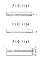
- Figs. 1 (A) through 1(C) are a schematic view illustrating the steps of a method embodying the present invention.
- reference numeral 1 indicates an Si 3 N 4 or SiC ceramic and reference numeral 2 indicates a metal being bonded to the ceramic.
- Reference numeral 3 designates a composite insert material made, for example, of NiO + Ni or Cu 2 O + Cu (comprising over 5% of a metal constituent) and reference numeral 4 indicates a soldering material whose melting point is lower than a melting point of the insert material 3.
- Brazing or soldering material is, for example, solder, Al, Ag, Cu, Ni and the like solders.
- the composite insert material 3 is deposited on the ceramic 1 by ion plating or spray coating to obtain a sub-assembly. Subsequently, the sub-assembly is subjected to thermal reaction-promoting treatment or processing in Fig. l(B), followed by brazing the metal 2 being bonded in Fig. 1(C).
- Fig. 1(A) The ion-plating of Fig. 1(A) is carried out as follows.
- Ni or Cu is placed in a crucible, melted and evaporated to effect the ion-plating.
- the atmosphere for the ion-plating is alternately changed between vacuum and oxygen atmospheres.
- an initial layer and a final layer are formed in vacuo. More particularly, Ni (or Cu) is obtained in vacuo and Ni or Cu is oxidized into NiO or Cu 2 O in an atmosphere of oxygen, by which a composite insert material of a laminate structure of NiO +-Ni (or Cu 2 O + Cu) is deposited on the ceramic.
- Ni or Cu is placed in a crucible, melted and evaporated for ion plating.
- the ion plating is effected by a procedure which comprises, after evacuation, feeding a predetermined amount of oxygen into a chamber in order to oxidize part of the metal heated and evaporated.
- a composite insert material having a predetermined ratio of NiO + Ni (or Cu 2 0 + Cu) is deposited on the ceramic.
- Two crucible Two crucible are provided. A metal (Al, Zr or the like) which is converted into a corresponding oxide is placed in one crucible and Ni or Cu is placed in the other crucible. The metals in the individual crucibles are melted and evaporated for the ion plating. The ion plating atmosphere should be alternately changed between high vacuum and oxygen atmospheres. As a principle, initial and final layers should be effected in vacuo. Ni is evaporated in vacuo and the other metal such as Al, Zr or the like is evaporated in an oxygen atmosphere where it is oxidized into Al 2 O 3 , Zr0 2 or the like.
- a composite insert material of the laminate structure such as, for example, of A1 2 0 3 + N i, A 1 2 0 3 + Cu, Zr0 2 + Ni, Zr0 2 + Cu or the like is deposited on the ceramic.
- Ni-Si alloy a metal capable of constituting nitride (Si, Ti or the like) and Ni or Cu (e.g. Ni-Si alloy, Cu-Si alloy, Ni-Ti alloy, Cu-Ti alloy or the like) is placed in a crucible which is subsequently evacuated to a vacuum. Thereafter, nitrogen gas is introduced into a reaction chamber where the alloy is heated and evaporated. For instance, with Ni-Si alloy, the evaporated Si which has very high affinity for nitrogen is converted into Si 3 N 4 . On the other hand, Ni is not nitrided and is deposited on the ceramic as it is. Thus, Si 3 N 4 + Ni are deposited on the ceramic.
- Si is nitrided but Cu is not nitrided, so that Si 3 N 4 + Cu are deposited on the ceramic.
- evaporate Ti has very high affinity for nitrogen and is converted into TiN, but Ni is not nitrided, so that TiN + Ni are deposited on the ceramic.
- Two crucible are provided in order that a metal capable of converting into nitride (e.g. Si, Ti or the like) is placed in one crucible and Ni or Cu is placed in the other crucible.
- a metal capable of converting into nitride e.g. Si, Ti or the like
- Ni or Cu is placed in the other crucible.
- the respective metals are fused and evaporated while alternately changing the atmosphere from a high vacuum atmosphers to a nitrogen gas atmosphere.
- initial and final layers are formed under vacuum.
- Ni or Cu is ion-plated in a high vacuum atmosphere and Si,
- Ni-Si alloy evaporated Si has very high affinity for C decomposed from acetylene and is converted into SiC, but no carbonization of Ni takes place. Thus, Ni is deposited on the ceramic as it is and SiC + Ni is formed on the ceramic.
- the spray coating method used is generally a plasma spray coating technique.
- the melting point of the composite insert material obtained by the ion plating, spray coating and the like is determined as the lowest melting point among melting points of oxides, nitrides, carbides, Ni and Cu. If an eutectic reaction proceeds, the eutectic point should be taken into account and the lowest temperature is taken as a melting point of a composite insert material.
- the thermal reaction-promoting treatment as in Fig. 1(B) is carried out in order to increase the bonding strength between the ion-plated or spray-coated composite insert material and the ceramic.
- This treatment is effected by heating at a temperature over 1/3 time a melting point of the composite insert material (the upper limit is the melting of the composite insert material in an inert gas or in vacuo for a time over 5 minutes.
- the melting point of the insert material NiO + Ni insert material is determined to have a melting point of 1438°C because Ni has a melting point of 1453°C, NiO has a melting point of 1957°C and the eutectic mixture of NiO and Ni has a melting point of 1438°C.
- Cu 2 O + Cu insert material is determined to have a melting point of 1065 because Cu has a melting point of 1083°C, Cu 2 0 has a melting point of 1230°C and the eutectic mixture of Cu 2 O + Cu has a melting point of 1065°C.
- a hot hydrostatic pressure treatment (hereinafter referred to simply as HIP treatment) may be used, in which a load of a Ar or the like gas pressure over 0.01 kg/mm 2 is used under such time and temperature conditions as used above.
- the temperature used is over 1/3 time the melting point of the insert material is due to the fact that at lower temperatures, the bonding reaction between the composite insert material and the ceramic proceeds only very slowly with a need of a long operation time, thus being unfavorable from the industrial point of view.
- the upper limit of the temperature is determined to be lower than the melting point of the composite insert material because higher temperatures result in melting and flowing-out of the insert material.
- the reason why the treating time is over 5 minutes is owing to the fact that when the time is less than 5 minutes, bonding between the composite insert material and the ceramic becomes insufficient.
- a brazing material which has a melting point lower than a melting point of an insert material is used for brazing the insert material and a metal being bonded.
- the reason why a low melting brazing material is used is due to the fact that thermal stress which will be produced according to the difference in thermal expansion coefficient between the ceramic 1 and the bonding metal 2 at the time of brazing is decreased in order to prevent crackings of the ceramic.
- the content of the metal component in the composite insert material is defined to be not less than 5 wt%. This is because when the content is less, the metal constituent is so small that the ability of bonding with a metal lowers and the ductility of the insert material itself is lost, so that the insert material is liable to crack.
- Si 3 0 4 or SiC and metals i.e. Si 3 0 4 and SiC are combined with covalent bonds and metals are based on metallic bonds, the bonding between them is very difficult.
- Another problem is that because of the poor toughness of Si 3 N 4 or SiC, these ceramics tend to crack due to the thermal stress produced during the bonding even when the ceramic and metal are bonded together.
- cermets of oxides + metals e.g. NiO + Ni or Cu 2 O + Cu, are used as the insert material. This leads to the following advantages.
- the thermal expansion coefficients of Si304, SiC, Ni and Cu are as follows.
- the insert material of the invention to which high strength NiO or Cu 2 O is added to form a cermet is higher in strength with an increase of joint strength.
- Oxides (NiO, Cu 2 O and the like) in the composite insert materials are the same oxides as SiO 2 contained in Si 3 0 4 or SiC ceramics in small amounts, M g O, A1 2 0 3 or Y 2 0 3 used as a sintering aid for Si304 and Al 2 O 3 or Be0 used as sintering aid for SiC. These oxides have such a crystal structure mainly made of ion bonds, so that when the composite insert material and the ceramic are heated at high temperatures, reactions take place and contribute to the bonding.
- a composite insert material is first deposited on a ceramic by ion plating or spray coating.
- the ion plating or spray coating is used, so that no matter how the ceramic is complicated in shape, the insert material can be conveniently deposited (this is difficult with foils).
- the thermal reaction-promoting treatment (including a heat treatment and HIP treatment described before) is followed with the following advantages and effects.
- Si in Si 3 N 4 or SiC and Ni or Cu in the insert material are sufficiently diffused when heated at high temperatures, resulting in a satisfactory metallurgical bonding or joint.
- fine voids of the insert material at the interface with the ceramic i.e. fine voids formed at the time of the ion plating or spray disappear by creep and plastic deformations caused by application of the pressure load, enhancing the bonding force.
- the HIP treatment is advantageous in that because a pressure of a hot gas is uniformly, three-dimensionally applied, the operation is possible even when the shape of the ceramic is very complicated, ensuring good bonding between the insert material and the ceramic.
- the pressure is applied three-dimensionally with a further advantage that there is little fear of producing cracks of the ceramic.
- the ceramic 1 and the bonding metal 2 have a substantial difference in thermal expansion coefficient, so that the ceramic is apt to crack by the thermal stress produced during the cooling operation after bonding.
- low melting brazing materials are used, so that a cooling temperature range decreases with a lowering of produced thermal stress, showing a remarkable effect of preventing cracking of the ceramic.
- metal components in the insert material and a bonding metal are metals which can be fundamentally welded very easily. Accordingly, such brazing materials as used before are used to form good joints.
- NiO and Cu 2 0 oxides in the composite insert materials of NiO + Ni and Cu 2 O + Cu there are used, instead of NiO and Cu 2 0 oxides in the composite insert materials of NiO + Ni and Cu 2 O + Cu, other metal oxides such as A1203, Zr0 2 and the like, metal nitrides such as TiN, si 3 N 4 and the like, and metal carbides such as TiC, UC, SiC and the like.
- the number of crucibles may be increased as desired.
- Oxygen gas is used for metal oxides and nitrogen gas is used for metal nitrides, followed by repeating the procedure described before.
- the composite insert material of Ni + TiN two crucible for Ni and Ti are used.
- the composite insert material of Ni + TiN is ion-plated.
- spray coating it will be sufficient to merely change a combination in mixing of powders.
- the melting point of an insert material is determined as the lowest melting point of an oxide, nitride or carbide and Ni or Cu. If an eutectic mixture exists, the melting point thereof should be taken into account in order to determine the lowest melting point.
- the nitrides in the composite insert material are the same nitrides as Si 3 N 4 ceramic and the carbides are the same carbide as SiC ceramic, with almost the same crystal structure. When heated at high temperatures, the composite insert material and the ceramic undergo the diffusion reaction, contributing to the bonding therebetween.
- brazing between the insert material and the bonding metal may be replaced by diffusion welding. Similar to the brazing, diffusion welding is effected at temperatures lower than a melting point of an insert material used so that thermal stress produced in the ceramic is reduced to prevent cracking of the ceramic.
- the diffusion welding is carried out under ordinary conditions including a pressure of 0.1 - 5 kg/mm 2 and a time of 5 minutes to 5 hours. Good results are obtained because the metal component (Ni or Cu) in the insert material and a bonding metal are both metals.
- the present invention is more particularly described by way of examples.
- Si 3 N 4 in the form of a 2 mm thick sheet was ion-plated on the surface thereof with a 20 ⁇ m thick layer of NiO + Ni (50% Ni and 50% NiO on the weight basis) and subjected to thermal reaction treatment in vacuo at a temperature of 1200°C for 30 minutes. Subsequently, a 3 mm thick SS 41 sheet which was used as a bonding metal was placed on the NiO + Ni layer and subjected to brazing with Ag at a temperature of 850°C for a time of 10 minutes.
- SiC in the form of a 2 mm thick sheet was provided, on which Cu 2 O + Cu (70% Cu, 30% Cu 2 0 on the weight basis) were subjected to plasma spray coating in a thickness of 100 ⁇ m and also to thermal reaction treatment in an atmosphere of Ar under conditions of a temperature of 1030°C and a treating time of 30 minutes.
- a round rod of Si 3 N 4 having a diameter of 10 mm and a length of 20 mm was provided and ion-plated on the outer surface thereof with NiO + Ni (90% Ni, 10% NiO on the weight basis) in a thickness of 30 pm, followed by the HIP treatment in an atmosphere of Ar under conditions of a temperature of 1100°C, an Ar gas pressure of 15 kg/mm 2 and a treating time of 30 minutes.
- a Kovar hollow cylinder used as a metal being bonded and having an inner diameter of 10.25 mm, an outer diameter of 16.25 mm and a length of 20 mm was provided, into which the Al 2 O 3 round rod applied with an Ag brazing paste was inserted, followed by brazing at a temperature of 850°C in an atmosphere of Ar for a time of 10 minutes.
- a cylinder of SiC having an inner diameter of 20 mm, an outer diameter of 25 mm and a length of 50 mm was provided and ion-plated on the outer surface thereof with A1 2 0 3 + Ni (80% Ni, 20% A1 2 0 3 on the weight basis) in a thickness of 20 ⁇ m, followed by the HIP treatment in an atmosphere of Ar under conditions of a temperature of 1100 C, an Ar gas pressure of 10 kg/mm2 and a treating time of 15 minutes.
- the SiC cylinder onto which an Sn-Pb solder was applied was inserted inserted into an Al cylinder used as a bonding metal and having an inner diameter of 25.25 mm, an outer diameter of 45.25 mm and a length of 50 mm, followed by brazing at a temperature of 250°C for 3 minutes.
- NiO + Ni 80% Ni, 20% NiO on the weight basis
- thermal reaction-promoting treatment in vacuo under conditions of a temperature of 1150°C and a treating time of 60 minutes.
- Si 3 N 4 + Ni ( 30 % Si 3 N 4 , 70% Ni on the weight basis) were ion-plated on a 2 mm thick Si 3 N 4 sheet in a thickness of 30 ⁇ m, followed by thermal reaction treatment in vacuo under conditions of a temperature of 1200°C, and a treating time of 15 minutes.
- SiC was provided as a 2 mm thick sheet and plasma.spray-coated with SiC + Ni (40% SiC, 60% Ni on the weight basis) in a thickness of 100 pm, followed by thermal reaction treatment in vacuo under conditions of a temperature of 1100°C and a time of 30 minutes.
- a 5 mm thick Kovar plate used as a metal being bonded was facing with the SiC + Ni surface, followed by diffusion welding in vacuo under conditions of a temperature of 1000°C, a pressure of 0.5 kg/mm 2 and a time of 1 hour.
Abstract
Description
- This invention relates to the art of bonding between ceramics and metals and more particularly, to a method for bonding ceramics and metals while preventing crackings of the ceramics.
- Broadly, known methods of bonding ceramics and metals together include (1) an adhesive method, (2) a metallizing method and (3) a spray coating method. However, these methods have the following drawbacks.
- (1) The adhesive method is the simplest method but adhesion strength at high temperatures is low.
- (2) The metallizing method is a method which comprises placing an Mo metallic powder such as Mo, Mo-Mn or the like on ceramics, heating the powder for metallizing in a moistening atmosphere, subjecting the metallized layer to Ni plating, and bonding a metal to the ceramic by brazing. However, this method is disadvantageous in difficulty of application depending on the type of ceramic. In addition, because of the high metallizing temperature, great thermal stress is exerted on the ceramic upon cooling, with the unfavorable tendency toward cracking.
- (3) The spray coating method is a method in which ceramic powder is fused and adhered to metals by spraying. The method is also disadvantageous in that the bonding strength is low and the sprayed ceramic becomes porous.
- As will be seen from the above, the prior art methods have such drawbacks that the bonding strength is not adequate, ceramics are liable to crack, and limitation is placed on the type of ceramic being applied.
- The present invention is accomplished to overcomes the above drawbacks.
- According to one embodiment of the invention, there is provided a method for bonding Si3N4 or SiC ceramics and metals which comprises the steps of depositing, on the ceramic material, an insert material consisting of a mixture of at least one metal selected from the group consisting of Ni and Cu and at least one metal compound selected from the group consisting of metal oxides, nitrides and carbides by ion plating or spray coating, subjecting the deposited insert material to thermal reaction-promoting treatment to permit strong metallurgical bond between the insert material and the ceramic material, and soldering a metal member and the surface of the insert material with a soldering material having a melting point lower than a melting point of the insert material.
- According to another embodiment of the invention, there is also provided a method for bonding Si3N4 or SiC ceramics and metals which comprises the steps of depositing, on the ceramic material, an insert material consisting of a mixture of at least one metal selected from the group consisting of Ni and Cu and at least one metal compound selected from the group consisting of metal oxides, nitrides and carbides by ion plating or spray coating, subjecting the deposited insert material to thermal reaction-promoting treatment to permit strong metallurgical bond between the insert material and the ceramic material, and brazing a metal member and the surface of the insert material by diffusion welding at a temperature lower than a melting point of the insert material.
- The insert materials used in the practice of the invention include composite materials of Ni and metal oxides such as NiO, Al2O3, Zr02 and the like, metal nitrides such as TiN, Si3N4 and the like, or metal carbides such as TiC, UC, SiC and the like, or mixtures of Cu and metal oxides such as Cu20, Al2O3, Zr02 and the like, metal nitrides such as TiN, Si3N4 and the like, or metal carbides such as TiC, UC, SiC and the like.
- In accordance with the method of the invention, prior to bonding or welding of Si3N4 or SiC ceramics and metals, the composite insert material is deposited on the ceramic by ion plating or spray coating. Thereafter, strong bonding is ensured by the thermal reaction-promoting treatment or processing. Finally, the insert material and the metal are completely bonded by brazing with a low melting brazing material or by diffusion welding at temperatures lower than a melting point of the insert material used. The method of the invention ensures not only flat lap joint bonding between ceramics and metals, but also sleeve joint bonding, bonding of ceramics to inner and outer surfaces of metallic cylinders and bondings of ceramics and metals along complicated configurations without involving crackings of the ceramics but with high bonding strength.
- Objects, advantages and features of the present invention will become apparent from the following detailed description with reference to the accompanying drawing.
- Figs. 1 (A) through 1(C) are a schematic view illustrating the steps of a method embodying the present invention.
- Reference is now made to the drawing and particularly to Figs. 1(A) through 1(C). In the figures, reference numeral 1 indicates an Si3N4 or SiC ceramic and
reference numeral 2 indicates a metal being bonded to the ceramic.Reference numeral 3 designates a composite insert material made, for example, of NiO + Ni or Cu2O + Cu (comprising over 5% of a metal constituent) and reference numeral 4 indicates a soldering material whose melting point is lower than a melting point of theinsert material 3. Brazing or soldering material is, for example, solder, Al, Ag, Cu, Ni and the like solders. - In Fig. l(A), the
composite insert material 3 is deposited on the ceramic 1 by ion plating or spray coating to obtain a sub-assembly. Subsequently, the sub-assembly is subjected to thermal reaction-promoting treatment or processing in Fig. l(B), followed by brazing themetal 2 being bonded in Fig. 1(C). - The ion-plating of Fig. 1(A) is carried out as follows.
- (1) Insert materials of oxides + Ni (or Cu)
- (1)-1 With oxides of Ni (or Cu)
- (First Method) Ni or Cu is placed in a crucible, melted and evaporated to effect the ion-plating. In this connection, it should be noted that the atmosphere for the ion-plating is alternately changed between vacuum and oxygen atmospheres. As a principle, an initial layer and a final layer are formed in vacuo. More particularly, Ni (or Cu) is obtained in vacuo and Ni or Cu is oxidized into NiO or Cu2O in an atmosphere of oxygen, by which a composite insert material of a laminate structure of NiO +-Ni (or Cu2O + Cu) is deposited on the ceramic.
- (Second Method) Ni or Cu is placed in a crucible, melted and evaporated for ion plating. In this connection, the ion plating is effected by a procedure which comprises, after evacuation, feeding a predetermined amount of oxygen into a chamber in order to oxidize part of the metal heated and evaporated. As a result, a composite insert material having a predetermined ratio of NiO + Ni (or Cu20 + Cu) is deposited on the ceramic.
- (1)-2 With the case where oxides other than NiO and Cu2O are used (Al2O3, Zro2 and the like).
- Two crucible are provided. A metal (Al, Zr or the like) which is converted into a corresponding oxide is placed in one crucible and Ni or Cu is placed in the other crucible. The metals in the individual crucibles are melted and evaporated for the ion plating. The ion plating atmosphere should be alternately changed between high vacuum and oxygen atmospheres. As a principle, initial and final layers should be effected in vacuo. Ni is evaporated in vacuo and the other metal such as Al, Zr or the like is evaporated in an oxygen atmosphere where it is oxidized into Al2O3, Zr02 or the like. As a result, a composite insert material of the laminate structure such as, for example, of A1 2 0 3 + Ni, A1 2 0 3 + Cu, Zr02 + Ni, Zr02 + Cu or the like is deposited on the ceramic.
- (First Method) An alloy of a metal capable of constituting nitride (Si, Ti or the like) and Ni or Cu (e.g. Ni-Si alloy, Cu-Si alloy, Ni-Ti alloy, Cu-Ti alloy or the like) is placed in a crucible which is subsequently evacuated to a vacuum. Thereafter, nitrogen gas is introduced into a reaction chamber where the alloy is heated and evaporated. For instance, with Ni-Si alloy, the evaporated Si which has very high affinity for nitrogen is converted into Si3N4. On the other hand, Ni is not nitrided and is deposited on the ceramic as it is. Thus, Si3N4 + Ni are deposited on the ceramic.
- Likewise, with Cu-Si alloy, Si is nitrided but Cu is not nitrided, so that Si3N4 + Cu are deposited on the ceramic.
- With Ni-Ti alloy, evaporate Ti has very high affinity for nitrogen and is converted into TiN, but Ni is not nitrided, so that TiN + Ni are deposited on the ceramic.
- With Cu-Ti alloy, Ti is nitrided but no nitriding of Cu takes place. TiN + Cu are deposited on the ceramic.
- (Second Method) Two crucible are provided in order that a metal capable of converting into nitride (e.g. Si, Ti or the like) is placed in one crucible and Ni or Cu is placed in the other crucible. The respective metals are fused and evaporated while alternately changing the atmosphere from a high vacuum atmosphers to a nitrogen gas atmosphere. As a principle, initial and final layers are formed under vacuum. Ni or Cu is ion-plated in a high vacuum atmosphere and Si,
- Ti or the like is ion-plated in a nitrogen atmosphere. As a result, composite insert materials having laminate structures such as, for example, of Si3N4 + Ni, Si3N4 + Cu, TiN + Ni, TiN + Cu and the like are deposited on the ceramic.
- (First Method) Alloys (Ni-Si alloy, Cu-Si alloy, Ni-W alloy, Cu-U alloy and the like) of metals capable of converting into carbides (Si, U and the like) and Ni or Cu are placed in a crucible and after evacuation, a predetermined amount of acetylene gas is charged into a reaction chamber, followed by heating and evaporating.
- With Ni-Si alloy, evaporated Si has very high affinity for C decomposed from acetylene and is converted into SiC, but no carbonization of Ni takes place. Thus, Ni is deposited on the ceramic as it is and SiC + Ni is formed on the ceramic.
- With Ni-W alloy, evaporated U has very high affinity for C and is converted into WC but no carbonization of Ni takes place. Thus, WC + Ni are deposited on the ceramic.
- With Cu-W alloy, W is carbonized but Cu is not carbonized, so that WC + Cu are deposited on the ceramic.
- (Second method) Two crucibles are provided and a metal (Si, W or the like) capable of forming a corresponding carbide is placed in one crucible. Ni or Cu is placed in the other crucible. While the atmosphere is changed between high vacuum and acetylene gas atmospheres, the metals are melted and evaporated. As a principle, initial and final layers are formed in vacuo. More particularly, Ni or Cu is ion-plated in vacuo and Si, W or the like is ion-plated in an atmosphere of acetylene gas, thereby depositing, on the ceramic, a composite insert material of a laminate structure such as SiC + N, SiC + Cu, WC + Ni, WC + Cu or the like.
- In case where composite insert materials are spray coated, it may be sufficient to merely change a combination in mixture of the above-indicated powders. The spray coating method used is generally a plasma spray coating technique. The melting point of the composite insert material obtained by the ion plating, spray coating and the like is determined as the lowest melting point among melting points of oxides, nitrides, carbides, Ni and Cu. If an eutectic reaction proceeds, the eutectic point should be taken into account and the lowest temperature is taken as a melting point of a composite insert material.
- The thermal reaction-promoting treatment as in Fig. 1(B) is carried out in order to increase the bonding strength between the ion-plated or spray-coated composite insert material and the ceramic. This treatment is effected by heating at a temperature over 1/3 time a melting point of the composite insert material (the upper limit is the melting of the composite insert material in an inert gas or in vacuo for a time over 5 minutes. With regard to the melting point of the insert material, NiO + Ni insert material is determined to have a melting point of 1438°C because Ni has a melting point of 1453°C, NiO has a melting point of 1957°C and the eutectic mixture of NiO and Ni has a melting point of 1438°C. Likewise, Cu2O + Cu insert material is determined to have a melting point of 1065 because Cu has a melting point of 1083°C, Cu20 has a melting point of 1230°C and the eutectic mixture of Cu2O + Cu has a melting point of 1065°C. A hot hydrostatic pressure treatment (hereinafter referred to simply as HIP treatment) may be used, in which a load of a Ar or the like gas pressure over 0.01 kg/mm2 is used under such time and temperature conditions as used above.
- The reason why the temperature used is over 1/3 time the melting point of the insert material is due to the fact that at lower temperatures, the bonding reaction between the composite insert material and the ceramic proceeds only very slowly with a need of a long operation time, thus being unfavorable from the industrial point of view. On the other hand, the upper limit of the temperature is determined to be lower than the melting point of the composite insert material because higher temperatures result in melting and flowing-out of the insert material. The reason why the treating time is over 5 minutes is owing to the fact that when the time is less than 5 minutes, bonding between the composite insert material and the ceramic becomes insufficient.
- In the brazing in Fig. l(C), a brazing material which has a melting point lower than a melting point of an insert material is used for brazing the insert material and a metal being bonded. The reason why a low melting brazing material is used is due to the fact that thermal stress which will be produced according to the difference in thermal expansion coefficient between the ceramic 1 and the
bonding metal 2 at the time of brazing is decreased in order to prevent crackings of the ceramic. - As described before, the content of the metal component in the composite insert material is defined to be not less than 5 wt%. This is because when the content is less, the metal constituent is so small that the ability of bonding with a metal lowers and the ductility of the insert material itself is lost, so that the insert material is liable to crack.
- The effects, advantages and features of the method of the invention are summarized below.
- (1) Because of the difference in structure between Si304 or SiC and metals, i.e. Si304 and SiC are combined with covalent bonds and metals are based on metallic bonds, the bonding between them is very difficult. Another problem is that because of the poor toughness of Si3N4 or SiC, these ceramics tend to crack due to the thermal stress produced during the bonding even when the ceramic and metal are bonded together.
- In the practice of the invention, so-called cermets of oxides + metals, e.g. NiO + Ni or Cu2O + Cu, are used as the insert material. This leads to the following advantages.
- 1. Ni or Cu which is a metal component in the composite insert material exhibits good metallurgical bonding with Si3N4 or SiC and thus good joints can be obtained. Because Si3N4 or SiC contains free Si therein (including free Si which is obtained by heating Si3N4 over 1000°C at which part of the ceramic starts to decompose thereby producing Si), the Si and Ni or Cu diffuse with each other when heated at high temperatures. At the same time, Si is dissolved in Ni and Cu to form a solid solution (the degree of solid solution of Si in Ni or Cu is about 5 wt: at normal temperatures), and thus good joints are obtained without forming any brittle layer.
- 2. Ni or Cu and the
bonding metal 2 are all metals, which have fundamentally good weldability, ensuring good joints. - 3. Assuming that Ni or Cu alone is used as an insert material and ion-plating or spray coating is effected on Si3N4 or SiC, followed by thermal reaction-promoting treatment in the subsequent step (step of Fig. 1(B)), great thermal stress is produced, during cooling, due to the difference in thermal expansion coefficient between Si3N4 or SiC and Ni or Cu. This leads to a high possibility of producing cracks in Si3N4 or SiC, needing an exact operation control for preventing formation of the cracks. In contrast, in the practice of the invention, NiO or Cu2O is added to Ni or Cu to form a cermet which has a smaller thermal expansion coefficient, thus causing the produced thermal stress to lower. Cracking of Si3O4 or SiC can be prevented.
- The thermal expansion coefficients of Si304, SiC, Ni and Cu are as follows.
- Si3N4, SiC: about 3 - 4 x 10⁻⁶ /°C Ni: about 13 x 10-6/°C Cu: about 17 x 10-6/°C
- 4. As compared with the case where Ni or Cu alone is used as an insert material, the insert material of the invention to which high strength NiO or Cu2O is added to form a cermet is higher in strength with an increase of joint strength.
- 5. Oxides (NiO, Cu2O and the like) in the composite insert materials are the same oxides as SiO2 contained in Si304 or SiC ceramics in small amounts, MgO, A1203 or Y203 used as a sintering aid for Si304 and Al2O3 or Be0 used as sintering aid for SiC. These oxides have such a crystal structure mainly made of ion bonds, so that when the composite insert material and the ceramic are heated at high temperatures, reactions take place and contribute to the bonding.
- (2) In the practice of the invention, a composite insert material is first deposited on a ceramic by ion plating or spray coating. The ion plating or spray coating is used, so that no matter how the ceramic is complicated in shape, the insert material can be conveniently deposited (this is difficult with foils).
- (3) According to the invention, the thermal reaction-promoting treatment (including a heat treatment and HIP treatment described before) is followed with the following advantages and effects.
- 1. Si in Si3N4 or SiC and Ni or Cu in the insert material are sufficiently diffused when heated at high temperatures, resulting in a satisfactory metallurgical bonding or joint. With the HIP treatment, fine voids of the insert material at the interface with the ceramic (i.e. fine voids formed at the time of the ion plating or spray disappear by creep and plastic deformations caused by application of the pressure load, enhancing the bonding force.
- 2. No matter how the shape of ceramics is complicated, this treatment is possible and thus the insert material can be strongly bonded to the oxide ceramics according to the metallurgical diffusion reaction.
- Especially, the HIP treatment is advantageous in that because a pressure of a hot gas is uniformly, three-dimensionally applied, the operation is possible even when the shape of the ceramic is very complicated, ensuring good bonding between the insert material and the ceramic. The pressure is applied three-dimensionally with a further advantage that there is little fear of producing cracks of the ceramic.
- (4) The sub-assembly of the insert material and the bonded metal which has undergone the thermal reaction-promoting treatment is subjected to brazing with a brazing material having a melting point lower than a melting point of the insert material used, thereby completing the bonding., These steps have the following effects.
- 1. In general, the ceramic 1 and the
bonding metal 2 have a substantial difference in thermal expansion coefficient, so that the ceramic is apt to crack by the thermal stress produced during the cooling operation after bonding. In the practice of the invention, low melting brazing materials are used, so that a cooling temperature range decreases with a lowering of produced thermal stress, showing a remarkable effect of preventing cracking of the ceramic. - 2. As a matter of course, metal components in the insert material and a bonding metal are metals which can be fundamentally welded very easily. Accordingly, such brazing materials as used before are used to form good joints.
- In the practice of the invention, there are used, instead of NiO and Cu20 oxides in the composite insert materials of NiO + Ni and Cu2O + Cu, other metal oxides such as A1203, Zr02 and the like, metal nitrides such as TiN, si3N4 and the like, and metal carbides such as TiC, UC, SiC and the like.
- In this connection, when ion plating is used, the number of crucibles may be increased as desired. Oxygen gas is used for metal oxides and nitrogen gas is used for metal nitrides, followed by repeating the procedure described before. For instance, with the composite insert material of Ni + TiN, two crucible for Ni and Ti are used. When Ni is subjected to ion plating in vacuo and Ti is subjected to ion plating in a nitrogen atmosphere alternately, the composite insert material of Ni + TiN is ion-plated. On the other hand, with spray coating, it will be sufficient to merely change a combination in mixing of powders. The melting point of an insert material is determined as the lowest melting point of an oxide, nitride or carbide and Ni or Cu. If an eutectic mixture exists, the melting point thereof should be taken into account in order to determine the lowest melting point.
- The nitrides in the composite insert material are the same nitrides as Si3N4 ceramic and the carbides are the same carbide as SiC ceramic, with almost the same crystal structure. When heated at high temperatures, the composite insert material and the ceramic undergo the diffusion reaction, contributing to the bonding therebetween.
- According to the method of the invention, brazing between the insert material and the bonding metal may be replaced by diffusion welding. Similar to the brazing, diffusion welding is effected at temperatures lower than a melting point of an insert material used so that thermal stress produced in the ceramic is reduced to prevent cracking of the ceramic. The diffusion welding is carried out under ordinary conditions including a pressure of 0.1 - 5 kg/mm2 and a time of 5 minutes to 5 hours. Good results are obtained because the metal component (Ni or Cu) in the insert material and a bonding metal are both metals.
- The present invention is more particularly described by way of examples.
- Si3N4 in the form of a 2 mm thick sheet was ion-plated on the surface thereof with a 20 µm thick layer of NiO + Ni (50% Ni and 50% NiO on the weight basis) and subjected to thermal reaction treatment in vacuo at a temperature of 1200°C for 30 minutes. Subsequently, a 3 mm thick SS 41 sheet which was used as a bonding metal was placed on the NiO + Ni layer and subjected to brazing with Ag at a temperature of 850°C for a time of 10 minutes.
- As a result, a good joint was obtained without involving any cracks in the Si3N4 and the joint was free of non-bonded portions over the entire bonded surface.
- SiC in the form of a 2 mm thick sheet was provided, on which Cu2O + Cu (70% Cu, 30% Cu20 on the weight basis) were subjected to plasma spray coating in a thickness of 100 µm and also to thermal reaction treatment in an atmosphere of Ar under conditions of a temperature of 1030°C and a treating time of 30 minutes.
- Thereafter, a 5 mm thick Kovar plate which was a bonding metal was placed on the Cu20 + Cu layer and subjected to brazing with Ag under conditions of a temperature of 850°C and a time of 10 minutes.
- As a result, there was obtained a good joint involving no cracks in the SiC and free of non-bonded portions over the entire bonded surface.
- A round rod of Si3N4 having a diameter of 10 mm and a length of 20 mm was provided and ion-plated on the outer surface thereof with NiO + Ni (90% Ni, 10% NiO on the weight basis) in a thickness of 30 pm, followed by the HIP treatment in an atmosphere of Ar under conditions of a temperature of 1100°C, an Ar gas pressure of 15 kg/mm2 and a treating time of 30 minutes.
- Subsequently, a Kovar hollow cylinder used as a metal being bonded and having an inner diameter of 10.25 mm, an outer diameter of 16.25 mm and a length of 20 mm was provided, into which the Al2O3 round rod applied with an Ag brazing paste was inserted, followed by brazing at a temperature of 850°C in an atmosphere of Ar for a time of 10 minutes.
- As a result, there was obtained a good joint involving no cracks in the Si3N4 and free of any non-bonded portions over the entire bonded surface of the cylinder.
- A cylinder of SiC having an inner diameter of 20 mm, an outer diameter of 25 mm and a length of 50 mm was provided and ion-plated on the outer surface thereof with A1203 + Ni (80% Ni, 20% A1203 on the weight basis) in a thickness of 20 µm, followed by the HIP treatment in an atmosphere of Ar under conditions of a temperature of 1100 C, an Ar gas pressure of 10 kg/mm2 and a treating time of 15 minutes.
- The SiC cylinder onto which an Sn-Pb solder was applied was inserted inserted into an Al cylinder used as a bonding metal and having an inner diameter of 25.25 mm, an outer diameter of 45.25 mm and a length of 50 mm, followed by brazing at a temperature of 250°C for 3 minutes.
- As a result, there was obtained a good joint involving no cracks in the SiC and free of any non-bonded portions over the entire bonded surface of the cylinder.
- Si3N4 in the form of a 2 mm thick sheet was provided, on which NiO + Ni (80% Ni, 20% NiO on the weight basis) were ion-plated in a thickness of 20 µm, followed by thermal reaction-promoting treatment in vacuo under conditions of a temperature of 1150°C and a treating time of 60 minutes.
- Subsequently, a 3 mm thick Kovar sheet which was used as a bonding metal was placed in face-to-face relation with the Ni0 + Ni surface, followed by diffusion welding in vacuo under conditions of a temperature of 900°C, a pressure of 2 kg/mm2 and a time of 1 hour.
- As a result, there was obtained a good joint involving no cracks in the Si3N4 and free of non-bonded portions over the entire surface of the joint.
- Si 3 N 4 + Ni (30% Si3N4, 70% Ni on the weight basis) were ion-plated on a 2 mm thick Si3N4 sheet in a thickness of 30 µm, followed by thermal reaction treatment in vacuo under conditions of a temperature of 1200°C, and a treating time of 15 minutes.
- Thereafter, a 4 mm thick SS 41 plate used as a metal being bonded was placed in face-to-face relation with the Si3N4 + Ni surface, followed by diffusion welding in vacuo under conditions of a temperature of 1000°C, a pressure of 0.3 kg/mm2 and a time of 1 hour.
- As a result, there was obtained a good joint involving no cracks in the Si3N4 and free of non-bonded portions over the entire joint surface.
- SiC was provided as a 2 mm thick sheet and plasma.spray-coated with SiC + Ni (40% SiC, 60% Ni on the weight basis) in a thickness of 100 pm, followed by thermal reaction treatment in vacuo under conditions of a temperature of 1100°C and a time of 30 minutes.
- Subsequently, a 5 mm thick Kovar plate used as a metal being bonded was facing with the SiC + Ni surface, followed by diffusion welding in vacuo under conditions of a temperature of 1000°C, a pressure of 0.5 kg/mm2 and a time of 1 hour.
- As a result, there was obtained a good joint involving no cracks in the SiC and free of non-bonded portions over the entire surface.
Claims (6)
ceramics and metals which comprises the steps of depositing, on the ceramic material, an insert material consisting of a mixture of at least one metal selected from the group consisting of Ni and Cu and at least one metal compound selected from the group consisting of metal oxides, nitrides and carbides by ion plating or spray coating, subjecting the deposited insert material to thermal reaction-promoting treatment to permit strong metallurgical bond between the insert material and the ceramic material, and brazing-a metal member and the surface of the insert material by diffusion welding at a temperature lower than a melting point of the insert material.
Applications Claiming Priority (2)
| Application Number | Priority Date | Filing Date | Title |
|---|---|---|---|
| JP237986/83 | 1983-12-19 | ||
| JP58237986A JPS60131874A (en) | 1983-12-19 | 1983-12-19 | Method of bonding ceramic and metal |
Publications (2)
| Publication Number | Publication Date |
|---|---|
| EP0146493A2 true EP0146493A2 (en) | 1985-06-26 |
| EP0146493A3 EP0146493A3 (en) | 1986-10-22 |
Family
ID=17023417
Family Applications (1)
| Application Number | Title | Priority Date | Filing Date |
|---|---|---|---|
| EP84730140A Withdrawn EP0146493A3 (en) | 1983-12-19 | 1984-12-13 | Method for bonding ceramics and metals |
Country Status (4)
| Country | Link |
|---|---|
| US (1) | US4624404A (en) |
| EP (1) | EP0146493A3 (en) |
| JP (1) | JPS60131874A (en) |
| KR (1) | KR890000912B1 (en) |
Cited By (1)
| Publication number | Priority date | Publication date | Assignee | Title |
|---|---|---|---|---|
| US20220055133A1 (en) * | 2017-05-10 | 2022-02-24 | Board Of Trustees Of Michigan State University | Brazing methods using porous interlayers and related articles |
Families Citing this family (21)
| Publication number | Priority date | Publication date | Assignee | Title |
|---|---|---|---|---|
| JPH0653622B2 (en) * | 1986-02-25 | 1994-07-20 | マツダ株式会社 | Method for joining silicon nitride member and metal member |
| US5744252A (en) * | 1989-09-21 | 1998-04-28 | The United States Of America As Represented By The Administrator Of The National Aeronautics And Space Administration | Flexible ceramic-metal insulation composite and method of making |
| US5277942A (en) * | 1990-10-12 | 1994-01-11 | Sumitomo Electric Industries, Ltd. | Insulating member and electric parts using the same |
| JP3291827B2 (en) * | 1993-03-18 | 2002-06-17 | 株式会社日立製作所 | Impeller, diffuser, and method of manufacturing the same |
| EP0667640A3 (en) * | 1994-01-14 | 1997-05-14 | Brush Wellman | Multilayer laminate product and process. |
| US5777259A (en) * | 1994-01-14 | 1998-07-07 | Brush Wellman Inc. | Heat exchanger assembly and method for making the same |
| US5490627A (en) * | 1994-06-30 | 1996-02-13 | Hughes Aircraft Company | Direct bonding of copper composites to ceramics |
| US6022426A (en) * | 1995-05-31 | 2000-02-08 | Brush Wellman Inc. | Multilayer laminate process |
| US6269714B1 (en) * | 1996-05-30 | 2001-08-07 | Kakoh Kiki Co., Ltd. | Cutter knife for thermoplastic resin pelletizer and production method of said cutter knife |
| US5953511A (en) * | 1997-04-08 | 1999-09-14 | National Instruments Corporation | PCI bus to IEEE 1394 bus translator |
| JP3792440B2 (en) * | 1999-06-25 | 2006-07-05 | 日本碍子株式会社 | Dissimilar member joining method and composite member joined by the joining method |
| US6332568B1 (en) * | 2000-01-14 | 2001-12-25 | Sandia Corporation | Wafer scale micromachine assembly method |
| JP4252231B2 (en) * | 2001-09-05 | 2009-04-08 | 日本碍子株式会社 | Manufacturing method of semiconductor wafer support member assembly and semiconductor wafer support member assembly |
| WO2004079762A2 (en) * | 2003-03-03 | 2004-09-16 | Koninklijke Philips Electronics N.V. | X-ray tube cathode assembly and interface reaction joining process |
| US7857194B2 (en) * | 2007-05-01 | 2010-12-28 | University Of Dayton | Method of joining metals to ceramic matrix composites |
| DE102007029031A1 (en) * | 2007-06-23 | 2008-12-24 | Fraunhofer-Gesellschaft zur Förderung der angewandten Forschung e.V. | Method for permanently connecting two components by soldering with glass or metal solder |
| JP4471004B2 (en) * | 2008-01-23 | 2010-06-02 | セイコーエプソン株式会社 | Method for forming joined body |
| JP4471002B2 (en) * | 2008-01-23 | 2010-06-02 | セイコーエプソン株式会社 | Method for forming joined body |
| JP4471003B2 (en) * | 2008-01-23 | 2010-06-02 | セイコーエプソン株式会社 | Method for forming joined body |
| CH700774A1 (en) | 2009-03-31 | 2010-10-15 | Alstom Technology Ltd | Doppellotelement, process for its preparation and uses thereof. |
| DE102015224464A1 (en) * | 2015-12-07 | 2017-06-08 | Aurubis Stolberg Gmbh & Co. Kg | Copper-ceramic substrate, copper semi-finished product for producing a copper-ceramic substrate and method for producing a copper-ceramic substrate |
Citations (3)
| Publication number | Priority date | Publication date | Assignee | Title |
|---|---|---|---|---|
| US3399076A (en) * | 1965-04-08 | 1968-08-27 | Mallory & Co Inc P R | Method of wetting silicon nitride |
| DE2533524A1 (en) * | 1975-07-26 | 1977-03-10 | Licentia Gmbh | Forming strongly adhering metal coating on glass or ceramic - by applying intermediate layer contg. copper and its oxides, and heating |
| EP0109814A2 (en) * | 1982-11-17 | 1984-05-30 | Ae Plc | Joining silicon nitride to metals |
Family Cites Families (9)
| Publication number | Priority date | Publication date | Assignee | Title |
|---|---|---|---|---|
| US2857663A (en) * | 1954-02-09 | 1958-10-28 | Gen Electric | Metallic bond |
| US3226822A (en) * | 1961-09-27 | 1966-01-04 | Eitel Mccullough Inc | Art of bonding ceramic to metal |
| US3324543A (en) * | 1965-03-26 | 1967-06-13 | Charles I Mcvey | Pressure bonded ceramic-to-metal gradient seals |
| US3813759A (en) * | 1971-09-09 | 1974-06-04 | English Electric Co Ltd | Method of brazing |
| JPH0233677B2 (en) * | 1981-11-28 | 1990-07-30 | Toyota Motor Co Ltd | CHITSUKAKEISOSERAMITSUKUSUTOKINZOKUTONOSETSUGOHOHO |
| JPS5895671A (en) * | 1981-11-30 | 1983-06-07 | トヨタ自動車株式会社 | Method of bonding ceramics and metals |
| US4452389A (en) * | 1982-04-05 | 1984-06-05 | The Bendix Corporation | Method for welding with the help of ion implantation |
| JPS59137379A (en) * | 1983-01-24 | 1984-08-07 | 工業技術院長 | Composite sintered ceramics and metal adhesion |
| JPS59218263A (en) * | 1983-05-25 | 1984-12-08 | Showa Alum Corp | Joining method of aluminum material and different kind of metallic material |
-
1983
- 1983-12-19 JP JP58237986A patent/JPS60131874A/en active Granted
-
1984
- 1984-12-12 KR KR1019840007865A patent/KR890000912B1/en not_active IP Right Cessation
- 1984-12-13 US US06/681,020 patent/US4624404A/en not_active Expired - Fee Related
- 1984-12-13 EP EP84730140A patent/EP0146493A3/en not_active Withdrawn
Patent Citations (3)
| Publication number | Priority date | Publication date | Assignee | Title |
|---|---|---|---|---|
| US3399076A (en) * | 1965-04-08 | 1968-08-27 | Mallory & Co Inc P R | Method of wetting silicon nitride |
| DE2533524A1 (en) * | 1975-07-26 | 1977-03-10 | Licentia Gmbh | Forming strongly adhering metal coating on glass or ceramic - by applying intermediate layer contg. copper and its oxides, and heating |
| EP0109814A2 (en) * | 1982-11-17 | 1984-05-30 | Ae Plc | Joining silicon nitride to metals |
Cited By (2)
| Publication number | Priority date | Publication date | Assignee | Title |
|---|---|---|---|---|
| US20220055133A1 (en) * | 2017-05-10 | 2022-02-24 | Board Of Trustees Of Michigan State University | Brazing methods using porous interlayers and related articles |
| US11724325B2 (en) * | 2017-05-10 | 2023-08-15 | Board Of Trustees Of Michigan State University | Brazing methods using porous interlayers and related articles |
Also Published As
| Publication number | Publication date |
|---|---|
| KR890000912B1 (en) | 1989-04-13 |
| JPS60131874A (en) | 1985-07-13 |
| EP0146493A3 (en) | 1986-10-22 |
| KR850004738A (en) | 1985-07-27 |
| JPH0367985B2 (en) | 1991-10-24 |
| US4624404A (en) | 1986-11-25 |
Similar Documents
| Publication | Publication Date | Title |
|---|---|---|
| US4624404A (en) | Method for bonding ceramics and metals | |
| EP0147360B1 (en) | Method for bonding ceramics and metals | |
| US4729504A (en) | Method of bonding ceramics and metal, or bonding similar ceramics among themselves; or bonding dissimilar ceramics | |
| US4602731A (en) | Direct liquid phase bonding of ceramics to metals | |
| US4624897A (en) | Clad brazing filler for bonding ceramic to metal, glass, or other ceramic and composites using such filler | |
| US4562121A (en) | Soldering foil for stress-free joining of ceramic bodies to metal | |
| US4559277A (en) | Ceramic and aluminum alloy composite | |
| EP0122522B1 (en) | Method of manufacturing sintered ceramic body | |
| EP0743131A1 (en) | Ceramic metal bonding | |
| JPH0573714B2 (en) | ||
| US3793705A (en) | Process for brazing a magnetic ceramic member to a metal member | |
| JP3095490B2 (en) | Ceramic-metal joint | |
| JPS62289396A (en) | Joining method for ceramics | |
| JPS6081071A (en) | Metal sheet material for ceramic bonding | |
| EP0922682A1 (en) | Method of forming a joint between a ceramic substrate and a metal component | |
| JP2541837B2 (en) | Method for manufacturing bonded body of ceramics and metal | |
| JP3370060B2 (en) | Ceramic-metal joint | |
| JPH0292872A (en) | Bonding between ceramic material and copper material | |
| JP3505212B2 (en) | Joint and method of manufacturing joint | |
| JPH0472793B2 (en) | ||
| JP2729751B2 (en) | Joining method of alumina ceramics and aluminum | |
| JPH01270574A (en) | Ceramics-joining component and joining method thereof | |
| JPH07187839A (en) | Nitride ceramics-metal joined body and its production | |
| JPH0649620B2 (en) | Method for joining ceramic member and metal member | |
| JPS6111912B2 (en) |
Legal Events
| Date | Code | Title | Description |
|---|---|---|---|
| PUAI | Public reference made under article 153(3) epc to a published international application that has entered the european phase |
Free format text: ORIGINAL CODE: 0009012 |
|
| AK | Designated contracting states |
Designated state(s): DE FR GB IT |
|
| 17P | Request for examination filed |
Effective date: 19850607 |
|
| PUAL | Search report despatched |
Free format text: ORIGINAL CODE: 0009013 |
|
| AK | Designated contracting states |
Kind code of ref document: A3 Designated state(s): DE FR GB IT |
|
| 17Q | First examination report despatched |
Effective date: 19880519 |
|
| STAA | Information on the status of an ep patent application or granted ep patent |
Free format text: STATUS: THE APPLICATION IS DEEMED TO BE WITHDRAWN |
|
| 18D | Application deemed to be withdrawn |
Effective date: 19891118 |
|
| RIN1 | Information on inventor provided before grant (corrected) |
Inventor name: OHMAE, TAKASHIHIROSHIMA TECH. INST., MITSUBISHI Inventor name: FUKAYA, YASUHIROHIROSHIMA TECH. INST., MITSUBISHI Inventor name: HIRAI, SHOZOHIROSHIMA TECH. INST., MITSUBISHI |