EP0146393A2 - Bogie for cable-drawn vehicle - Google Patents
Bogie for cable-drawn vehicle Download PDFInfo
- Publication number
- EP0146393A2 EP0146393A2 EP84308818A EP84308818A EP0146393A2 EP 0146393 A2 EP0146393 A2 EP 0146393A2 EP 84308818 A EP84308818 A EP 84308818A EP 84308818 A EP84308818 A EP 84308818A EP 0146393 A2 EP0146393 A2 EP 0146393A2
- Authority
- EP
- European Patent Office
- Prior art keywords
- cable
- guideway
- car
- disposed
- sheaves
- Prior art date
- Legal status (The legal status is an assumption and is not a legal conclusion. Google has not performed a legal analysis and makes no representation as to the accuracy of the status listed.)
- Granted
Links
- 238000006073 displacement reaction Methods 0.000 claims description 8
- 230000000712 assembly Effects 0.000 claims description 4
- 238000000429 assembly Methods 0.000 claims description 4
- 230000001133 acceleration Effects 0.000 description 1
- 238000007598 dipping method Methods 0.000 description 1
- 230000000694 effects Effects 0.000 description 1
- 230000001771 impaired effect Effects 0.000 description 1
- 238000009434 installation Methods 0.000 description 1
- 239000012212 insulator Substances 0.000 description 1
- 238000004519 manufacturing process Methods 0.000 description 1
- 238000012986 modification Methods 0.000 description 1
- 230000004048 modification Effects 0.000 description 1
- 238000004806 packaging method and process Methods 0.000 description 1
Images

Classifications
-
- B—PERFORMING OPERATIONS; TRANSPORTING
- B61—RAILWAYS
- B61F—RAIL VEHICLE SUSPENSIONS, e.g. UNDERFRAMES, BOGIES OR ARRANGEMENTS OF WHEEL AXLES; RAIL VEHICLES FOR USE ON TRACKS OF DIFFERENT WIDTH; PREVENTING DERAILING OF RAIL VEHICLES; WHEEL GUARDS, OBSTRUCTION REMOVERS OR THE LIKE FOR RAIL VEHICLES
- B61F9/00—Rail vehicles characterised by means for preventing derailing, e.g. by use of guide wheels
-
- B—PERFORMING OPERATIONS; TRANSPORTING
- B61—RAILWAYS
- B61B—RAILWAY SYSTEMS; EQUIPMENT THEREFOR NOT OTHERWISE PROVIDED FOR
- B61B12/00—Component parts, details or accessories not provided for in groups B61B7/00 - B61B11/00
- B61B12/02—Suspension of the load; Guiding means, e.g. wheels; Attaching traction cables
-
- B—PERFORMING OPERATIONS; TRANSPORTING
- B61—RAILWAYS
- B61B—RAILWAY SYSTEMS; EQUIPMENT THEREFOR NOT OTHERWISE PROVIDED FOR
- B61B7/00—Rope railway systems with suspended flexible tracks
- B61B7/02—Rope railway systems with suspended flexible tracks with separate haulage cables
Definitions
- This invention relates to cable-drawn vehicles for travelling in a guideway and, more particularly, to a bogie for attaching the vehicle to the cable and for interacting with a guiderail in the guideway.
- One type of transportation system is a generally horizontal transportation system in which passengers are moved in a vehicle or cab in a guideway.
- a closed loop of cable or rope runs along one side of the guideway, and it has two opposite moving lengths, one that is attached to the vehicle to drive the vehicle back and forth along the length of the guideway.
- the cable is driven bidirectionally by an electric motor at one end of the guideway, and is controlled by supervisory equipment to control the stopping, starting, acceleration and speed of the car.
- the cable rides on sheaves that are located along the side of the guideway.
- An arm that extends from the vehicle connects to the cable which drives the vehicle.
- the guideway determines the general direction of the vehicle, and the cable provides the driving force for moving it in the guideway, but directional control is provided to the vehicle by a guiderail that extends along the length of the guideway in conjunction with a rail follower on the vehicle.
- the arm and the rail follower comprise a "bogie.”
- the sheaves that support both lengths of the cable are primarily vertical to support the weight of the cable. But, in curved sections of the guideway, where the vehicle turns left or right, the particular sheave that supports that length of cable that drives the vehicle is oriented at a small angle to the vertical to accommodate the combined horizontal and vertical loads created in 7 turns.
- a transportation system including a car; a generally horizontal quideway in which the car moves longitudinally; a cable driven by a motor and disposed longitudinally along a side of the guideway for imparting motion to the car; a guiderail for providing lateral guidance to the car as it moves in the guideway and being mounted in an upper portion of the guideway and having oppositely facing sides facing towards and away from the cable respectively; a plurality of sheaves disposed at selected locations and within a range of orientations along the side of the guideway and upon which the cable rides, said sheaves defining a cable path and providing lateral and/or vertical support to the cable depending on their orientation; a cable clamp for attaching the car in driving relationship to the cable, and two cable supports associated therewith, one support being disposed forward of the cable clamp and the other being disposed rearward of the cable clamp, the clamp acting to displace the cable laterally from the cable path and said supports acting respectively to pick up the cable from and replace the cable onto the sheaves as the car moves past the
- the sheaves when the guideway changes directions, the orientation of the sheaves changes and when the guideway dips, as in passing through a valley, the sheaves are disposed above the cable.
- the guiderail is preferably mounted along a wall of the guideway, rather than on the base thereof.
- the cable clamp preferably displaces the cable a large amount from the sheaves, in comparison to the amount by which it is displaced by the cable supports.
- the supports are preferably disposed so as to substantially occupy the cross sectional area of the guideway that is defined by the large displacement of the cable as caused by attachment to the cable clamp.
- Fig. 1 is shown a transportation system of the prior art wherein a cable 10 imparts motion to a car 12 attached thereto by an arm 13. Since control over the cable motion effects control over the car motion, the use of elevator motors and controls is applicable to such a system.
- a guideway 14 provides support for the car 12 which is shown suspended on air cushions 16. Thus the car 12 is free to move laterally as well as longitudinally in the guideway 14.
- lateral guidance for the car 12 is provided by a guiderail 18 which is located at the base of the guideway 14 and a corresponding rail follower assembly 20 on the car 12.
- the arm 13 and the rail follower 20 together comprise a "bogie".
- the cable 10 rides on sheaves 22 which guide and support the cable.
- the sheaves 22 are positioned at selected locations along the guideway 14 and may be oriented in a number of ways. For instance, the sheave 22 is shown oriented vertically, beneath the cable 10, to provide vertical support to the cable 10. This configuration provides adequate cable support for straight runs, including those wherein the guideway crests a hill.
- the sheaves 22 are oriented to provide both lateral and vertical support to the cable. For instance, if the guideway were curving toward the cable, the sheave would be oriented as shown by the phantom sheave 22A. Similarly, if the guideway were curving away from the cable, the sheave would be oriented as shown by the phantom sheave 22B.
- a guiderail 30 is not disposed on the base of the guideway 14, but rather is disposed in an upper portion of the guideway attached "upside down" to a wall (not illustrated) or beneath a landing 32 in the guideway.
- the guiderail 30 is disposed longitudinally in the guideway 14 and has a face 34 that is oriented towards the cable 10 and a face 36 that is oriented away from the cable 10. Both faces 34,36 are perpendicular to the base of the guideway 14 and the guiderail has a thickness associated with the distance between the two faces 34,36.
- a rail follower assembly 38 is mounted to a frame 40 which is attached to or part of the frame of the car 12.
- a tire 42 and a tire 44 are journaled to the frame 40,and the clearance between the tires, in other words, between their peripheries, corresponds to the thickness of the guiderail so that the tires 42,44 snugly cooperate with the guiderail 30 to provide lateral guidance for the car 12, which is suspended in the guideway 14 by the air-cushion assembly 16.
- the tires 42,44 have an outer diameter on the order of fifteen inches(381mn).Each tire defines and occupies a portion of the cross-sectional area of the guideway 14.
- the cross-sectional areas of the guideway 14 that are occupied by the various elements described herein are significant in the context of packaging a bogie to occupy the least amount of space, which translates into guideway width and height savings, without sacrificing performance.
- a backup guidance system comprising two safety rollers 46,48 (shown in phantom), each of which is journaled to the frame 40.
- the roller 46 is disposed within the cross-sectional area defined by the tire 42,and the roller 48 is disposed within the cross-sectional area defined by the tire 44.
- the clearance between the periphery of the rollers 46,48 is greater than the thickness of the guiderail 30, but not much greater, so that the rollers will provide lateral guidance to the car 12 in the event of a failure of the primary guidance system (i.e., the tires).
- the lateral play inherent in the backup guidance system must be taken into account in the design of the guideway to allow for worst-case clearance between the car 12 and any obstructions in the guideway 14, and it is preferable that the play not be sufficient to allow the cable to jump off of the sheaves.
- the sheaves 22 One of the major consumers of cross-sectional area in the guideway 14 is the sheaves 22, one of which is shown in solid lines.
- the cable 10 rides on the sheaves 22, or pulleys, which provide support for the cable and also establish a cable path 50 in the guideway. Since the cable 10 is a closed loop, there is also a return cable path (not shown), inclusion of which in the drawing would only obfuscate the teachings herein.
- the guideway follows a straight and level course. Therefore, the sheaves are disposed as shown by the solid-lined sheave 22. However, other cases are possible. For instance, the guideway may veer toward the cable.
- the sheave must be oriented so as to provide lateral, as well as vertical support for the cable, and is thus shown as the phantom sheave 22A.
- the guideway veers away from the cable and the sheave must be oriented as shown by the phantom sheave 22B.
- the guideway may also crest a hill, in which case the sheave would be oriented in its normal position (22).
- the guideway dips, and it is necessary to provide downward vertical support on the cable, and the sheave must be oriented vertically, above the cable 10, as shown by the phantom sheave 22C.
- the guideway may simultaneously be cresting a hill and turning, in which case the sheave would be in a configuration as shown by the phantom sheaves 22A,22B or in any of the configurations included therebetween (not shown).
- the guideway dips, it-is permissible only that it be turning towards the cable, which would require a sheave 22D.
- a dipping turn away from the cable would require a sheave to be oriented in the space occupied by the tire 42 and other bogie elements as discussed hereinafter. This design limitation must be accounted for in the planning and layout of a guideway.
- a cable clamp 54 attaches the cable 10 to the car 12.
- the cable clamp must be large, on the order of three to four inches in each dimension, to accommodate the driving force imparted by the cable 10 to the car 12. Since the cable clamp 54 is large, the cable 10 must be displaced from the cable path 50, in other words, from its normal position in the sheaves 22 to be clamped by the cable clamp 54. Otherwise, the clamp 54 would impinge on the sheave 22, 22A, 22B, 22C or 22D. Stated succinctly, the cross-sectional area occupied by the clamp 54 cannot coincide with the cross-sectional area occupied by the range of sheave configurations.
- Fig.. 3 provides another perspective of this situation. Therein it may be seen that the cable clamp 54 displaces the cable 10 laterally fran the cable path 50 and, in factalso liftsthe cable 10 entirely off of the nearby sheave 22. This displacement defines an offset cable path 55, the cross-sectional area of which, in relation to the guideway 14, is best seen in Fig. 2. But, continuing with the discussion of Fig. 3, it is easily seen that the large displacement involved in attaching the cable 10 to the car would quickly derail the cable 10 from the sheaves 22 without additional measures.
- cable supports 56,56 are provided both foreward and rearward of the cable clamp 54 to pick up the cable from a sheave and replace the cable back onto a sheave as the car moves past the sheaves in the guideway. Since a cable support 56 carries no load other than any tension induced by the displacement of the cable 10, a cable support 56 may simply be a thin strap 58 at the end of an arm 60. As a matter of fact, the tension of the displaced cable will tend to hold the cable in the arm 60 and the strap 58 is provided merely to retain the cable 10 in the arm 60 in the event that there is a loss of tension in the cable 10.
- the dimensions of the cable support 56 and the amount by which it displaces the cable 10 from the cable path 50 are small in comparison to the dimensions of the cable clamp and the amount by which the cable is displaced from the cable path thereby.
- the cable supports 56 are shown disposed in close proximity to the rail followers 38,38, this is simply a matter of manufacturing convenience,and the cable supports 56 may be located anywhere along the frame 40 so long as their foreward and rearward relationship to the cable clamp 54 is maintained.
- the ultimate location of the cable-engaging end of the arm 60 determines the small displacement 61 of the cable 10 from its path 50. Since the strap 58 and the arm 60 are small, the displacement 61 can be correspondingly small, and varies slightly from sheave configuration to sheave configuration. Again, nonimpingement of the cable support 56 with the sheaves is essential. Therefore, the cross-sectional area occupied by the cable support 56 cannot be coincident with the cross-sectional area defined by the range of sheave configurations.
- the offset cable path 55 defines and occupies a portion of the cross-sectional area of the guideway, and disposing the arm 60, or at least a significant portion thereof, within the cross-sectional area defined by the offset cable path 55.
- a portion of the arm 60 could also be disposed within the cross sectional area defined by the tire 42.
- the cable clamp 54 is located so that it occupies substantially the same cross-sectional area that is already occupied by the tire 42 on the cable side of the rail.
- Another preferred advantageous feature of this invention is the' high location of the guiderail 30 and the rail follower assembly 38 which provides additional roll stability for the car.
- the location of major guideway space- consuming elements within coincidental cross-sectional areas of the guideway, and providing for a maximum range of sheave configurations is also achieved by this invention.
- a set of power rails 64 are mounted via standoff insulators 66 to a bracket 68 that is mounted to the guideway 14.
- Power collectors 70 are provided on the car 10 and may be mounted as shown to the frame 40 and in proximity to the rail follower assembly 30 in order to receive power from the power rails 64. Communication may also occur over the power rails 64 in a manner known to the art.
- Other functions, such as position sensing, may be provided by a module 72 attached to the bracket 68 and a module 74 attached to the frame 40, which modules 72,74 are positioned to cooperate with each other.
Abstract
Description
- This invention relates to cable-drawn vehicles for travelling in a guideway and, more particularly, to a bogie for attaching the vehicle to the cable and for interacting with a guiderail in the guideway.
- One type of transportation system is a generally horizontal transportation system in which passengers are moved in a vehicle or cab in a guideway. A closed loop of cable or rope runs along one side of the guideway, and it has two opposite moving lengths, one that is attached to the vehicle to drive the vehicle back and forth along the length of the guideway. The cable is driven bidirectionally by an electric motor at one end of the guideway, and is controlled by supervisory equipment to control the stopping, starting, acceleration and speed of the car. The cable rides on sheaves that are located along the side of the guideway. An arm that extends from the vehicle connects to the cable which drives the vehicle. The guideway determines the general direction of the vehicle, and the cable provides the driving force for moving it in the guideway, but directional control is provided to the vehicle by a guiderail that extends along the length of the guideway in conjunction with a rail follower on the vehicle. The arm and the rail follower comprise a "bogie."
- In straight sections of the guideway the sheaves that support both lengths of the cable are primarily vertical to support the weight of the cable. But, in curved sections of the guideway, where the vehicle turns left or right, the particular sheave that supports that length of cable that drives the vehicle is oriented at a small angle to the vertical to accommodate the combined horizontal and vertical loads created in 7turns.
- Therefore, it is an object of this invention to provide a bogie for a cable-drawn vehicle that occupies a minimum amount of space, or cross-sectional area in the guideway, and that performs its functions as well as, if not better than, the apparatus of the prior art, for instance, by providing improved roll stability and by allowing for dips, as when the guideway passes through a valley.
- According to one aspect of the invention, there is provided a transportation system including a car; a generally horizontal quideway in which the car moves longitudinally; a cable driven by a motor and disposed longitudinally along a side of the guideway for imparting motion to the car; a guiderail for providing lateral guidance to the car as it moves in the guideway and being mounted in an upper portion of the guideway and having oppositely facing sides facing towards and away from the cable respectively; a plurality of sheaves disposed at selected locations and within a range of orientations along the side of the guideway and upon which the cable rides, said sheaves defining a cable path and providing lateral and/or vertical support to the cable depending on their orientation; a cable clamp for attaching the car in driving relationship to the cable, and two cable supports associated therewith, one support being disposed forward of the cable clamp and the other being disposed rearward of the cable clamp, the clamp acting to displace the cable laterally from the cable path and said supports acting respectively to pick up the cable from and replace the cable onto the sheaves as the car moves past the sheaves in the guideway; two rail follower assemblies each including two wheels which cooperate with respective oppositely facing sides of the guiderail,one assembly being disposed forwardly of the cable clamp and the other being disposed rearwardly of the cable clamp; the configuration of the system being such that the cable clamp is disposed substantially within that portion of the cross-sectional area of the guideway occupied by the wheel which cooperates with the side of the guiderail facing the cable, and such that one or more of the sheaves may be oriented vertically above the cable.
- Other aspects of the invention are defined in the appended claims.
- In the preferred embodiment, when the guideway changes directions, the orientation of the sheaves changes and when the guideway dips, as in passing through a valley, the sheaves are disposed above the cable. The guiderail is preferably mounted along a wall of the guideway, rather than on the base thereof. The cable clamp preferably displaces the cable a large amount from the sheaves, in comparison to the amount by which it is displaced by the cable supports. The supports are preferably disposed so as to substantially occupy the cross sectional area of the guideway that is defined by the large displacement of the cable as caused by attachment to the cable clamp.
- An embodiment of the invention will now be described by way of example only and with reference to the accompanying drawings of which:
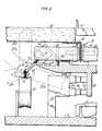
- Fig. 1 is a front partial cutaway view of a car, guideway, and other associated elements of the prior art;
- Fig. 2 is a cross-section of the bogie of this invention and associated guideway; and
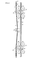
- Fig. 3 is a partial top view of the bogie of this invention.
- In Fig. 1 is shown a transportation system of the prior art wherein a cable 10 imparts motion to a
car 12 attached thereto by anarm 13. Since control over the cable motion effects control over the car motion, the use of elevator motors and controls is applicable to such a system. Aguideway 14 provides support for thecar 12 which is shown suspended onair cushions 16. Thus thecar 12 is free to move laterally as well as longitudinally in theguideway 14. As thecar 12 moves longitudinally in theguideway 14, lateral guidance for thecar 12 is provided by aguiderail 18 which is located at the base of theguideway 14 and a correspondingrail follower assembly 20 on thecar 12. Thearm 13 and therail follower 20 together comprise a "bogie". - The cable 10 rides on
sheaves 22 which guide and support the cable. Thesheaves 22 are positioned at selected locations along theguideway 14 and may be oriented in a number of ways. For instance, thesheave 22 is shown oriented vertically, beneath the cable 10, to provide vertical support to the cable 10. This configuration provides adequate cable support for straight runs, including those wherein the guideway crests a hill. When theguideway 14 curves, thesheaves 22 are oriented to provide both lateral and vertical support to the cable. For instance, if the guideway were curving toward the cable, the sheave would be oriented as shown by the phantom sheave 22A. Similarly, if the guideway were curving away from the cable, the sheave would be oriented as shown by thephantom sheave 22B. - The bogie shown in Fig. 2 is suitable for installation on a car, such as is shown in Fig. 1, provided that certain changes in the guideway configuration are made. More particularly, a
guiderail 30 is not disposed on the base of theguideway 14, but rather is disposed in an upper portion of the guideway attached "upside down" to a wall (not illustrated) or beneath alanding 32 in the guideway. Theguiderail 30 is disposed longitudinally in theguideway 14 and has aface 34 that is oriented towards the cable 10 and aface 36 that is oriented away from the cable 10. Bothfaces guideway 14 and the guiderail has a thickness associated with the distance between the twofaces - A
rail follower assembly 38 is mounted to aframe 40 which is attached to or part of the frame of thecar 12. Atire 42 and atire 44 are journaled to theframe 40,and the clearance between the tires, in other words, between their peripheries, corresponds to the thickness of the guiderail so that thetires guiderail 30 to provide lateral guidance for thecar 12, which is suspended in theguideway 14 by the air-cushion assembly 16. Thetires guideway 14. The cross-sectional areas of theguideway 14 that are occupied by the various elements described herein are significant in the context of packaging a bogie to occupy the least amount of space, which translates into guideway width and height savings, without sacrificing performance. - In the event of a single or multiple tire failure lateral guidance for the
car 12 would be impaired. Therefore, a backup guidance system is provided that comprises twosafety rollers 46,48 (shown in phantom), each of which is journaled to theframe 40. Theroller 46 is disposed within the cross-sectional area defined by thetire 42,and theroller 48 is disposed within the cross-sectional area defined by thetire 44. The clearance between the periphery of therollers guiderail 30, but not much greater, so that the rollers will provide lateral guidance to thecar 12 in the event of a failure of the primary guidance system (i.e., the tires). The lateral play inherent in the backup guidance system must be taken into account in the design of the guideway to allow for worst-case clearance between thecar 12 and any obstructions in theguideway 14, and it is preferable that the play not be sufficient to allow the cable to jump off of the sheaves. - One of the major consumers of cross-sectional area in the
guideway 14 is thesheaves 22, one of which is shown in solid lines. The cable 10 rides on thesheaves 22, or pulleys, which provide support for the cable and also establish acable path 50 in the guideway. Since the cable 10 is a closed loop, there is also a return cable path (not shown), inclusion of which in the drawing would only obfuscate the teachings herein. In the general case, the guideway follows a straight and level course. Therefore, the sheaves are disposed as shown by the solid-linedsheave 22. However, other cases are possible. For instance, the guideway may veer toward the cable. In that case, the sheave must be oriented so as to provide lateral, as well as vertical support for the cable, and is thus shown as the phantom sheave 22A. In another case, the guideway veers away from the cable and the sheave must be oriented as shown by thephantom sheave 22B. The guideway may also crest a hill, in which case the sheave would be oriented in its normal position (22). In another case the guideway dips, and it is necessary to provide downward vertical support on the cable, and the sheave must be oriented vertically, above the cable 10, as shown by thephantom sheave 22C. Furthermore, the guideway may simultaneously be cresting a hill and turning, in which case the sheave would be in a configuration as shown by thephantom sheaves 22A,22B or in any of the configurations included therebetween (not shown). However, when the guideway dips, it-is permissible only that it be turning towards the cable, which would require a sheave 22D. A dipping turn away from the cable would require a sheave to be oriented in the space occupied by thetire 42 and other bogie elements as discussed hereinafter. This design limitation must be accounted for in the planning and layout of a guideway. Therefore, there exists a range of permissible sheave configurations between thesheave 22B and clockwise (as shown) through to thesheave 22C which define a cross-sectional area of the guideway which, since the sheaves are fixed to theguideway 14, is not available to be occupied by any of the apparatus associated with the movingcar 12. - A
cable clamp 54 attaches the cable 10 to thecar 12. The cable clamp must be large, on the order of three to four inches in each dimension, to accommodate the driving force imparted by the cable 10 to thecar 12. Since thecable clamp 54 is large, the cable 10 must be displaced from thecable path 50, in other words, from its normal position in thesheaves 22 to be clamped by thecable clamp 54. Otherwise, theclamp 54 would impinge on thesheave clamp 54 cannot coincide with the cross-sectional area occupied by the range of sheave configurations. - The top view of Fig.. 3 provides another perspective of this situation. Therein it may be seen that the
cable clamp 54 displaces the cable 10 laterally fran thecable path 50 and, in factalso liftsthe cable 10 entirely off of thenearby sheave 22. This displacement defines an offsetcable path 55, the cross-sectional area of which, in relation to theguideway 14, is best seen in Fig. 2. But, continuing with the discussion of Fig. 3, it is easily seen that the large displacement involved in attaching the cable 10 to the car would quickly derail the cable 10 from thesheaves 22 without additional measures. Therefore, cable supports 56,56 are provided both foreward and rearward of thecable clamp 54 to pick up the cable from a sheave and replace the cable back onto a sheave as the car moves past the sheaves in the guideway. Since acable support 56 carries no load other than any tension induced by the displacement of the cable 10, acable support 56 may simply be athin strap 58 at the end of anarm 60. As a matter of fact, the tension of the displaced cable will tend to hold the cable in thearm 60 and thestrap 58 is provided merely to retain the cable 10 in thearm 60 in the event that there is a loss of tension in the cable 10. Therefore the dimensions of thecable support 56 and the amount by which it displaces the cable 10 from thecable path 50 are small in comparison to the dimensions of the cable clamp and the amount by which the cable is displaced from the cable path thereby. Whereas the cable supports 56 are shown disposed in close proximity to therail followers frame 40 so long as their foreward and rearward relationship to thecable clamp 54 is maintained. - More significant aspects of the cable supports are described with reference to Fig. 2. The ultimate location of the cable-engaging end of the
arm 60 determines the small displacement 61 of the cable 10 from itspath 50. Since thestrap 58 and thearm 60 are small, the displacement 61 can be correspondingly small, and varies slightly from sheave configuration to sheave configuration. Again, nonimpingement of thecable support 56 with the sheaves is essential. Therefore, the cross-sectional area occupied by thecable support 56 cannot be coincident with the cross-sectional area defined by the range of sheave configurations. This is most conveniently achieved by taking advantage of the fact that the offsetcable path 55 defines and occupies a portion of the cross-sectional area of the guideway, and disposing thearm 60, or at least a significant portion thereof, within the cross-sectional area defined by the offsetcable path 55. A portion of thearm 60 could also be disposed within the cross sectional area defined by thetire 42. - Since guideway space, i.e., cross-sectional area, is at a premium, it is important to package the various elements of the bogie in as small a space as possible. Therefore, the
cable clamp 54 is located so that it occupies substantially the same cross-sectional area that is already occupied by thetire 42 on the cable side of the rail. - Another preferred advantageous feature of this invention is the' high location of the
guiderail 30 and therail follower assembly 38 which provides additional roll stability for the car. The location of major guideway space- consuming elements within coincidental cross-sectional areas of the guideway, and providing for a maximum range of sheave configurations is also achieved by this invention. - It is necessary in the case of blowers for the hover
pad 16 and in any case for car lighting and other electrical functions within thecar 12 to provide power to thecar 12. Therefore, a set of power rails 64 are mounted via standoff insulators 66 to abracket 68 that is mounted to theguideway 14. Power collectors 70 are provided on the car 10 and may be mounted as shown to theframe 40 and in proximity to therail follower assembly 30 in order to receive power from the power rails 64. Communication may also occur over the power rails 64 in a manner known to the art. Other functions, such as position sensing, may be provided by a module 72 attached to thebracket 68 and amodule 74 attached to theframe 40, whichmodules 72,74 are positioned to cooperate with each other. - The foregoing description of this invention is intended to enable those skilled in the art to practice the invention. Various other embodiments and modifications as are suited to the particular use contemplated will become apparent upon examination and practice of the invention.
Claims (14)
wherein
the clearance between the first safety roller(s) and the second safety ro1lens) being greater than the thickness of the guiderail.
Priority Applications (1)
| Application Number | Priority Date | Filing Date | Title |
|---|---|---|---|
| AT84308818T ATE58098T1 (en) | 1983-12-16 | 1984-12-17 | ROLLER SUPPORT FRAME FOR THE TRACTION CABLE OF A CABLE CAR. |
Applications Claiming Priority (2)
| Application Number | Priority Date | Filing Date | Title |
|---|---|---|---|
| US06/562,137 US4630543A (en) | 1983-12-16 | 1983-12-16 | Bogie for cable-drawn vehicle |
| US562137 | 1983-12-16 |
Publications (3)
| Publication Number | Publication Date |
|---|---|
| EP0146393A2 true EP0146393A2 (en) | 1985-06-26 |
| EP0146393A3 EP0146393A3 (en) | 1987-04-22 |
| EP0146393B1 EP0146393B1 (en) | 1990-11-07 |
Family
ID=24244958
Family Applications (1)
| Application Number | Title | Priority Date | Filing Date |
|---|---|---|---|
| EP84308818A Expired - Lifetime EP0146393B1 (en) | 1983-12-16 | 1984-12-17 | Bogie for cable-drawn vehicle |
Country Status (7)
| Country | Link |
|---|---|
| US (1) | US4630543A (en) |
| EP (1) | EP0146393B1 (en) |
| AT (1) | ATE58098T1 (en) |
| AU (1) | AU563338B2 (en) |
| CA (1) | CA1281235C (en) |
| DE (1) | DE3483565D1 (en) |
| ZA (1) | ZA849089B (en) |
Families Citing this family (7)
| Publication number | Priority date | Publication date | Assignee | Title |
|---|---|---|---|---|
| ATE105533T1 (en) * | 1990-06-29 | 1994-05-15 | Streiff Ag Mathias | CHASSIS FOR A TRACK-LIMITED VEHICLE. |
| JPH06107166A (en) * | 1992-08-27 | 1994-04-19 | Otis Elevator Co | Rope jack device for level elevator |
| GB9701446D0 (en) * | 1997-01-24 | 1997-03-12 | Scapa Group Plc | Warp changing apparatus |
| DE19936031C1 (en) * | 1999-07-30 | 2001-03-01 | Wenzel Juergen Michael | Carrier and guide rail that can be laid on the floor |
| US6477964B1 (en) * | 1999-10-15 | 2002-11-12 | Tygard Machine And Manufacturing Company | Guide system for a forklift |
| AT502840B1 (en) * | 2005-11-24 | 2007-08-15 | Innova Patent Gmbh | AMUSEMENT EQUIPMENT ACCORDING TO THE TYPE OF A GIANT WHEEL |
| AT517116A1 (en) * | 2015-05-13 | 2016-11-15 | Spitzbart Berthold Mag | Four-wheeled vehicle whose wheels are individually movable in vertical planes |
Citations (1)
| Publication number | Priority date | Publication date | Assignee | Title |
|---|---|---|---|---|
| FR2500799A1 (en) * | 1981-02-27 | 1982-09-03 | Otis Elevator Co | TRANSPORT SYSTEM COMPRISING AT LEAST ONE VEHICLE TRACTED BY LATERAL CABLE |
Family Cites Families (8)
| Publication number | Priority date | Publication date | Assignee | Title |
|---|---|---|---|---|
| DE63055C (en) * | P. JORISSEN in Düsseldorf-Grafenberg | Device for the automatic introduction of the pull rope into the coupling device of taxiway cars | ||
| US336245A (en) * | 1886-02-16 | Gripping device for cable railways | ||
| US482279A (en) * | 1892-09-06 | Andrew j | ||
| US3675583A (en) * | 1969-10-29 | 1972-07-11 | Transportation Technology | Speed and slip controlled traction drive |
| FR2337067A1 (en) * | 1975-12-31 | 1977-07-29 | Poma 2000 Sa | OWN SITE TRANSPORT INSTALLATION WITH TRIPLE CLAMP FOR COUPLING VEHICLES TO TRACTOR CABLES |
| DE2627523C2 (en) * | 1976-06-18 | 1985-04-04 | Daimler-Benz Ag, 7000 Stuttgart | Traffic system with fairway and mechanically transversely guided road vehicles |
| US4089272A (en) * | 1976-11-22 | 1978-05-16 | Westinghouse Electric Corp. | Transportation vehicle guidance apparatus |
| DE2807984A1 (en) * | 1977-02-25 | 1978-08-31 | Ingenieria Transito Moderna | MONORAR RAIL WITH DERAILING PROTECTED TURNING STUDS GUIDED BY MEANS OF WHEELS AND LATERAL GUIDING ELEMENTS ON RAIL BEAMS |
-
1983
- 1983-12-16 US US06/562,137 patent/US4630543A/en not_active Expired - Fee Related
-
1984
- 1984-11-21 ZA ZA849089A patent/ZA849089B/en unknown
- 1984-12-11 CA CA000469772A patent/CA1281235C/en not_active Expired - Lifetime
- 1984-12-12 AU AU36549/84A patent/AU563338B2/en not_active Ceased
- 1984-12-17 AT AT84308818T patent/ATE58098T1/en active
- 1984-12-17 DE DE8484308818T patent/DE3483565D1/en not_active Expired - Lifetime
- 1984-12-17 EP EP84308818A patent/EP0146393B1/en not_active Expired - Lifetime
Patent Citations (1)
| Publication number | Priority date | Publication date | Assignee | Title |
|---|---|---|---|---|
| FR2500799A1 (en) * | 1981-02-27 | 1982-09-03 | Otis Elevator Co | TRANSPORT SYSTEM COMPRISING AT LEAST ONE VEHICLE TRACTED BY LATERAL CABLE |
Also Published As
| Publication number | Publication date |
|---|---|
| DE3483565D1 (en) | 1990-12-13 |
| EP0146393A3 (en) | 1987-04-22 |
| US4630543A (en) | 1986-12-23 |
| ZA849089B (en) | 1985-07-31 |
| CA1281235C (en) | 1991-03-12 |
| EP0146393B1 (en) | 1990-11-07 |
| AU3654984A (en) | 1985-06-20 |
| ATE58098T1 (en) | 1990-11-15 |
| AU563338B2 (en) | 1987-07-02 |
Similar Documents
| Publication | Publication Date | Title |
|---|---|---|
| US5845581A (en) | Monorail system | |
| CA1209858A (en) | Transportation system having a cable drawn vehicle | |
| US7624684B2 (en) | Cable suspended, self leveling tram with self-propelled tractor bogie | |
| CN101062662A (en) | F rail vehicle running mechanism | |
| CA2349463A1 (en) | Monorail system | |
| HK1065289A1 (en) | Monorail system | |
| JPH01146630A (en) | Car base plate automatic induction system | |
| GB2305645A (en) | Overhead monorail - lowers carriage to load/unload passengers or goods | |
| EP0146393B1 (en) | Bogie for cable-drawn vehicle | |
| CN115352283A (en) | Permanent magnetic suspension rail transit system | |
| JP3091587B2 (en) | Vertical and horizontal moving elevator | |
| WO2002018256A1 (en) | Elevator device | |
| CN111775977A (en) | Boosting damping system of rail car and rail car operation control method | |
| CN201033543Y (en) | Running frame | |
| US4993327A (en) | Apparatus for collective transportation of passengers, of metropolitan type with automatic drive by independent traction trucks using propulsion notably by linear motor | |
| US11685414B2 (en) | Device for transporting at least one passenger | |
| JPH05131920A (en) | Hybrid-type circulation cableway usable with railway | |
| EP1726503A3 (en) | Monorail system | |
| KR100459973B1 (en) | Passenger transportation system | |
| JP2985807B2 (en) | Maglev train vehicle | |
| CN110775079A (en) | Magnetic suspension rail train | |
| JPH0235801B2 (en) | JIKIFUJOSHIKITETSUDONOKIDOBUNKISOCHI | |
| JP3090821B2 (en) | Self-propelled elevator | |
| CN116348356A (en) | Conveying system | |
| JP2574524Y2 (en) | Monorail device |
Legal Events
| Date | Code | Title | Description |
|---|---|---|---|
| PUAI | Public reference made under article 153(3) epc to a published international application that has entered the european phase |
Free format text: ORIGINAL CODE: 0009012 |
|
| AK | Designated contracting states |
Designated state(s): AT CH DE FR GB IT LI |
|
| PUAL | Search report despatched |
Free format text: ORIGINAL CODE: 0009013 |
|
| AK | Designated contracting states |
Kind code of ref document: A3 Designated state(s): AT CH DE FR GB IT LI |
|
| 17P | Request for examination filed |
Effective date: 19870626 |
|
| 17Q | First examination report despatched |
Effective date: 19881212 |
|
| ITF | It: translation for a ep patent filed |
Owner name: BARZANO' E ZANARDO ROMA S.P.A. |
|
| GRAA | (expected) grant |
Free format text: ORIGINAL CODE: 0009210 |
|
| AK | Designated contracting states |
Kind code of ref document: B1 Designated state(s): AT CH DE FR GB IT LI |
|
| REF | Corresponds to: |
Ref document number: 58098 Country of ref document: AT Date of ref document: 19901115 Kind code of ref document: T |
|
| ET | Fr: translation filed | ||
| REF | Corresponds to: |
Ref document number: 3483565 Country of ref document: DE Date of ref document: 19901213 |
|
| PLBE | No opposition filed within time limit |
Free format text: ORIGINAL CODE: 0009261 |
|
| STAA | Information on the status of an ep patent application or granted ep patent |
Free format text: STATUS: NO OPPOSITION FILED WITHIN TIME LIMIT |
|
| 26N | No opposition filed | ||
| PGFP | Annual fee paid to national office [announced via postgrant information from national office to epo] |
Ref country code: FR Payment date: 19911107 Year of fee payment: 8 |
|
| PGFP | Annual fee paid to national office [announced via postgrant information from national office to epo] |
Ref country code: AT Payment date: 19911112 Year of fee payment: 8 |
|
| PGFP | Annual fee paid to national office [announced via postgrant information from national office to epo] |
Ref country code: GB Payment date: 19911114 Year of fee payment: 8 |
|
| PGFP | Annual fee paid to national office [announced via postgrant information from national office to epo] |
Ref country code: DE Payment date: 19911121 Year of fee payment: 8 Ref country code: CH Payment date: 19911121 Year of fee payment: 8 |
|
| ITTA | It: last paid annual fee | ||
| PG25 | Lapsed in a contracting state [announced via postgrant information from national office to epo] |
Ref country code: GB Effective date: 19921217 Ref country code: AT Effective date: 19921217 |
|
| PG25 | Lapsed in a contracting state [announced via postgrant information from national office to epo] |
Ref country code: LI Effective date: 19921231 Ref country code: CH Effective date: 19921231 |
|
| GBPC | Gb: european patent ceased through non-payment of renewal fee |
Effective date: 19921217 |
|
| PG25 | Lapsed in a contracting state [announced via postgrant information from national office to epo] |
Ref country code: FR Effective date: 19930831 |
|
| REG | Reference to a national code |
Ref country code: CH Ref legal event code: PL |
|
| PG25 | Lapsed in a contracting state [announced via postgrant information from national office to epo] |
Ref country code: DE Effective date: 19930901 |
|
| REG | Reference to a national code |
Ref country code: FR Ref legal event code: ST |