EP0145385B1 - Rail car tipplers and tippler installations - Google Patents
Rail car tipplers and tippler installations Download PDFInfo
- Publication number
- EP0145385B1 EP0145385B1 EP84308141A EP84308141A EP0145385B1 EP 0145385 B1 EP0145385 B1 EP 0145385B1 EP 84308141 A EP84308141 A EP 84308141A EP 84308141 A EP84308141 A EP 84308141A EP 0145385 B1 EP0145385 B1 EP 0145385B1
- Authority
- EP
- European Patent Office
- Prior art keywords
- tippler
- rail car
- tipping
- platform
- main beam
- Prior art date
- Legal status (The legal status is an assumption and is not a legal conclusion. Google has not performed a legal analysis and makes no representation as to the accuracy of the status listed.)
- Expired - Lifetime
Links
- 238000009434 installation Methods 0.000 title claims description 7
- 239000000969 carrier Substances 0.000 claims description 6
- 230000005540 biological transmission Effects 0.000 claims description 2
- 238000006073 displacement reaction Methods 0.000 description 3
- 238000005452 bending Methods 0.000 description 2
- 238000010276 construction Methods 0.000 description 2
- 239000000463 material Substances 0.000 description 2
- 238000009412 basement excavation Methods 0.000 description 1
- 230000005484 gravity Effects 0.000 description 1
- 230000004048 modification Effects 0.000 description 1
- 238000012986 modification Methods 0.000 description 1
- 230000003068 static effect Effects 0.000 description 1
Images

Classifications
-
- B—PERFORMING OPERATIONS; TRANSPORTING
- B65—CONVEYING; PACKING; STORING; HANDLING THIN OR FILAMENTARY MATERIAL
- B65G—TRANSPORT OR STORAGE DEVICES, e.g. CONVEYORS FOR LOADING OR TIPPING, SHOP CONVEYOR SYSTEMS OR PNEUMATIC TUBE CONVEYORS
- B65G67/00—Loading or unloading vehicles
- B65G67/02—Loading or unloading land vehicles
- B65G67/24—Unloading land vehicles
- B65G67/32—Unloading land vehicles using fixed tipping installations
- B65G67/46—Apparatus for lifting and tilting
Definitions
- This invention relates to tipplers for rail cars and to receiving and storing installations incorporating such tipplers.
- Rail car tipplers are known for the discharge of bulk materials from a rail car into a hopper by tipping the rail car about a longitudinal axis (see for instance US-A-3811580).
- Such tipplers comprise a rotary structure on which the rail car is held as it is inverted to empty its contents.
- the structure has transverse frames of arcuate or circular form through which it is mounted on rollers, and clamping means that keep the rail car firmly in place as it tips with the rotation of the structure on the rollers.
- the hopper into which the car contents are tipped must be disposed completely below the level of the tippler, which can require a great deal of expense in excavation and the provision of foundations.
- the charging means that brings each rail car onto the tippler platform must be a vehicle that can be driven on and off the platform, usually between the rails of the track, which introduces further complications and also means that the cars can be moved only slowly so that the cycle time is increased. Furthermore, it is not possible to provide a static weighbridge for rail cars on the tippler so it becomes difficult and complicated to get reliable weight data.
- open-sided tipplers have been constructed having arcuate transverse frames which allow the use of a side-arm charger running on a track outside the tippler but require a substantially heavier structure to provide the necessary strength and they are therefore larger and more expensive to produce.
- One known form of open-sided tippler is substantially little more than the modification of the first described form of tippler in which the transverse rings of the structure are open-ended and so it shares the other disadvantages of that first form of tippler.
- Another form of open-sided tippler comprises a pair of opposite end plates between which the hopper is situated to one side of the tippler, the end plates being connected together by a first beam against which the side of a rail car rests as it is being tipped, and a further beam on which a series of transverse top clamping beams are pivotally supported to hold the rail car in place when it is inverted.
- the two end plates also carry toothed racks which are both engaged by the rotary drive means to synchonize the movement of the end frames as the rail car is tipped.
- This form of tippler can employ a side-arm charger, and the hopper need not be placed completely below the tippler structure, but the arrangement has a number of disadvantages, however.
- the tippler structure must be larger and heavier, so that its constructional costs are greater.
- the re-positioning of the hopper results in the rail cars being lifted a considerable distance through an arcuate path and their weight must be at least partly balanced by ballast, both these factors requiring larger driving forces, with further constructional and operating costs.
- An object of the present invention is to provide an open-sided rail car tippler in which these disadvantages are at least partly avoided.
- an open-sided rail car tippler comprising a rail car platform disposed in a tipping structure comprising a main longitudinal beam mounted at its opposite ends on respective pivot mountings supporting the structure rotatably for tipping the platform with a rail car on it, said main beam transmitting the weight of the structure and rail car to said mountings, top clamping means for holding the rail car on the platform when the tipped, said main beam carrying the clamping means through pivot supports fixed to the main beam to define an axis disposed above the axis of the main beam end pivot mountings when the tippler is at rest.
- the main longitudinal beam serves as a load-carrying member both in the rest and tipped positions of the tippler.
- the rail car platform substantially spans the distance between said end pivot mountings.
- Such a construction allows the tippler to be of a smaller size for a given size of rail car, with resulting savings in construction and operating costs.
- the tipping axis defined by said mountings is laterally offset from the rail car platform and is so located that a plane containing it and passing through the plane of the platform rails at its intersection with a vertical from the further lateral edge of the platform subtends an angle from the horizontal not substantially more than 30°, and preferably less than 20°.
- This arrangement allows the sweep radius of the tippler to be kept at a minimum when the rail car is being tipped, so that the side arm charger can be located closer to the track on the rail car platform.
- the size, and therefore the cost of the charger arm can be significantly reduced and the reduced size of the arm can also lead to faster operating times because of the smaller distance it has to move when engaging with and disengaging from a rail car.
- the rail car tippler forms part of an installation that comprises a hopper for the discharge from said tippler disposed to the opposite side of the rotary tipping axis to that of the rail car platform when at rest, the hopper having an entry opening extending longitudinally of the tippler as far as said pivot mountings.
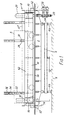
- the tippler comprises a rail car platform 2 which, in the rest position shown in Figs. 1 and 2, is supported by a weighbridge 4 comprising load cells 4a set on a fixed foundation 6.
- the tippler further comprises a rotatable tipping structure 8 mounted on bearing blocks 10 on fixed foundations 12 at opposite ends of the tippler. These foundations overhang the ends of the entry opening of a hopper 14 into which the rail cars are discharged by the tippler.
- the rotary tipping structure comprises a main box beam 16 which extends between the bearing blocks 10 and stub shafts 18 project from its ends to be journalled in the blocks.
- An arcuate end plate 20 is fixed to each end of the beam, one of the end plates carrying an arcuate toothed rim 22, with a centre coincident with the tipping axis of the bearing blocks, engaged by drive pinions 24 of a pair of motors 26 (electric or hydraulic) that provide the rotary drive for tipping the rotary structure on its bearing blocks 10. It is also possible to provide both end plates with toothed racks for the rotary drive.
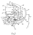
- Brackets 28 project from the top of the beam to provide pivots 30 for respective carriers 32 on the upper ends of which transverse clamping beams 34 are suspended through pivots 36.
- the carriers are interconnected by a cross-member 38 that lies between the end plates 20 and that has end flanges 40 on each of which are mounted a pair of pawls 42.
- On the adjacent face of each end plate is an arcuate rack 44, having a centre coincident with the carrier pivots 30, for engagement by the pawls.
- Each pawl is fixed to a pivot pin 46 journalled in its end flange 40 and the pins also have weighted arms 48 fixed to them so that the pawls are pivoted with the tilting of the structure 8 on the end bearing blocks 10.
- the carrier and clamping beam assembly is so ballasted that, in the rest position shown in Fig. 2, a fixed abutment bar 50 at each end of the tippler engages one of the pawl pivot pins and thus holds the carriers 32 with the clamping beams 34 raised to the position illustrated.
- the rail car platform is connected to the main rotary structure of the tippler by rollers 52 mounted on axially projecting pins at opposite ends of the platform, the rollers engaging in slots 54 in brackets 56 on the end plates. In the rest position shown in Figs. 1 and 2, the rollers are clear of the ends of the slots and the platform is supported wholly by the weighbridge 4. The ends of the platform extend over the end plates 20 so that the platform spans the distance between the outer faces of the pivot bearing blocks 10.
- a loaded rail car R is driven onto the rails 58 of the rail car platform in a conventional manner, e.g. using a side-arm charger (not shown).
- the loaded weight can be measured and recorded, using the weighbridge, before the tippler motors 26 begin to tip the rotary structure clockwise (as seen in Figs. 2-4), with the rail car on it.
- Fig. 3 shows the final tipping position after 150° rotation, with the rail car and platform supported solely through the clamping beams 34 and the buffer bar 62. It may be noted that in this position, as when first moving from the initial rest position, the weight of the rotary structure and the rail car remain supported directly through the main beam 16 and its pivot supports 10, 18.
- the rail car remains clamped by the beams 34 during the return movement of the tippler from the fully inverted position, until it comes close to the final rest position.
- the reducing angle of tilt of the structure brings the heel of the arm 48 of the pawl that is leading in this direction of movement against the fixed bar 50, so pivoting the pawl out of engagement with the rack 44.
- An integral extension 48a on that pawl arm contacts the arm of the trailing pawl of the pair and so causes that second pawl to disengage from the rack at the same time.
- the clamping beams then return automatically to their raised poTutomati- cally to their raised positions due to the gravity forces on the carrier and clamping beam assembly.
- the tippler illustrated is able to handle rail cars of widely differing heights as exemplified by the maximum and minimum profiles R", R' shown in Fig. 2. This is largely a result of the pivoting of the clamping beam carrier 32 through pivots 30 fixed on the main beam 16 above the tipping axis.
- the pawls 42 will adopt different final positions, as will be clear from Fig. 4 showing the smallest rail car R" fully tipped, but the relative positions of the tipping axis and the axis of the pivots 30 ensure that the range of final positions required to lock the clamping beams in place is accommodated within a moderate length of the rack 44.
- the height of the main structure tipping axis defined by the supports 10 is relatively low in comparison with conventional open-sided tip- piers.
- the loaded wagon is lifted a smaller distance because of this, so that less power is needed to tip its contents.
- the final tipped position of rail car is further displaced laterally as compared with the conventional tippler, so that it is possible while using relatively light gauge material to accommodate the rigid form of box beam illustrated; this not only carries the bending loads of the loaded rail car and platform but is also sufficiently stiff in torsion to transmit the drive from one end plate to the opposite end plate, thereby saving over the costs of a drive transmission to both ends of the rotary structure that would be required in a conventional tippler.
- the lift of the loaded rail car is less, it is possible to use less ballast to even out the power loading in operation, so that less power is needed to drive the tippler.
- the area swept by the tippler as it is pivoted has a lateral extent that projects only a very small distance beyond the rail car gauge, so that the side arm charger can be positioned close to the rail car and the length of its side arm kept small. Because of the large bending loads the side arm must accept this results in a significant cost reduction as well as a saving of space, and the smaller side arm can be swung more quickly into and out of engagement with the rail car so that the cycle operation time can be reduced.
- the height of the tipping axis is such that, with respect to the top plane of the rails on the platform and the point of intersection in that plane of a vertical from the outer edge of the platform, i.e. that the lateral edge of the platform further from the tipping axis defined by the bearing blocks 10, the axis subtends an angle of substantially 16°.
- the advantages outlined above can be obtained to a greater or lesser extent with larger angles, e.g. up to 20-25°, but are less evident when the angle exceeds some 30°.
- the hopper entry can be extended beyond the end plates. It is therefore possible to shorten the length of the tippler producing further savings (in the illustrated example all the above-ground structure is kept within the length of the rail car platform).
- a rail car can be positioned at or close to the very end of the tippler and that it is possible to use two such tipplers in tandem in order to empty a pair of coupled rail cars simultaneously, a mode of operation that brings obvious savings but is not possible with conventional open-sided tipplers.
- Such an arrangement is particularly simple when, as in the illustrated arrangement, the drive of each tippler is at one end only, the drives of the tamdem tipplers then preferably being located at their mutually remote ends.
- the tip- piers can otherwise have the constructional features already described and shown and further illustration will not be needed by those skilled in the art.
Landscapes
- Engineering & Computer Science (AREA)
- Aviation & Aerospace Engineering (AREA)
- Mechanical Engineering (AREA)
- Handcart (AREA)
- Loading Or Unloading Of Vehicles (AREA)
- Vehicle Cleaning, Maintenance, Repair, Refitting, And Outriggers (AREA)
- Forklifts And Lifting Vehicles (AREA)
Description
- This invention relates to tipplers for rail cars and to receiving and storing installations incorporating such tipplers.
- Rail car tipplers are known for the discharge of bulk materials from a rail car into a hopper by tipping the rail car about a longitudinal axis (see for instance US-A-3811580). Such tipplers comprise a rotary structure on which the rail car is held as it is inverted to empty its contents. The structure has transverse frames of arcuate or circular form through which it is mounted on rollers, and clamping means that keep the rail car firmly in place as it tips with the rotation of the structure on the rollers.
- When the transverse frames are in the form of rings the hopper into which the car contents are tipped must be disposed completely below the level of the tippler, which can require a great deal of expense in excavation and the provision of foundations. The charging means that brings each rail car onto the tippler platform must be a vehicle that can be driven on and off the platform, usually between the rails of the track, which introduces further complications and also means that the cars can be moved only slowly so that the cycle time is increased. Furthermore, it is not possible to provide a static weighbridge for rail cars on the tippler so it becomes difficult and complicated to get reliable weight data.
- To avoid such problems as these, open-sided tipplers have been constructed having arcuate transverse frames which allow the use of a side-arm charger running on a track outside the tippler but require a substantially heavier structure to provide the necessary strength and they are therefore larger and more expensive to produce. One known form of open-sided tippler is substantially little more than the modification of the first described form of tippler in which the transverse rings of the structure are open-ended and so it shares the other disadvantages of that first form of tippler. Another form of open-sided tippler comprises a pair of opposite end plates between which the hopper is situated to one side of the tippler, the end plates being connected together by a first beam against which the side of a rail car rests as it is being tipped, and a further beam on which a series of transverse top clamping beams are pivotally supported to hold the rail car in place when it is inverted. The two end plates also carry toothed racks which are both engaged by the rotary drive means to synchonize the movement of the end frames as the rail car is tipped.
- This form of tippler can employ a side-arm charger, and the hopper need not be placed completely below the tippler structure, but the arrangement has a number of disadvantages, however. The tippler structure must be larger and heavier, so that its constructional costs are greater. In addition, the re-positioning of the hopper results in the rail cars being lifted a considerable distance through an arcuate path and their weight must be at least partly balanced by ballast, both these factors requiring larger driving forces, with further constructional and operating costs.
- An object of the present invention is to provide an open-sided rail car tippler in which these disadvantages are at least partly avoided.
- According to one aspect of the present invention, there is provided an open-sided rail car tippler comprising a rail car platform disposed in a tipping structure comprising a main longitudinal beam mounted at its opposite ends on respective pivot mountings supporting the structure rotatably for tipping the platform with a rail car on it, said main beam transmitting the weight of the structure and rail car to said mountings, top clamping means for holding the rail car on the platform when the tipped, said main beam carrying the clamping means through pivot supports fixed to the main beam to define an axis disposed above the axis of the main beam end pivot mountings when the tippler is at rest.
- With this arrangement, the main longitudinal beam serves as a load-carrying member both in the rest and tipped positions of the tippler.
- Preferably, the rail car platform substantially spans the distance between said end pivot mountings. Such a construction allows the tippler to be of a smaller size for a given size of rail car, with resulting savings in construction and operating costs.
- Preferably, the tipping axis defined by said mountings is laterally offset from the rail car platform and is so located that a plane containing it and passing through the plane of the platform rails at its intersection with a vertical from the further lateral edge of the platform subtends an angle from the horizontal not substantially more than 30°, and preferably less than 20°. This arrangement allows the sweep radius of the tippler to be kept at a minimum when the rail car is being tipped, so that the side arm charger can be located closer to the track on the rail car platform. The size, and therefore the cost of the charger arm can be significantly reduced and the reduced size of the arm can also lead to faster operating times because of the smaller distance it has to move when engaging with and disengaging from a rail car.
- According to another aspect of the invention, the rail car tippler forms part of an installation that comprises a hopper for the discharge from said tippler disposed to the opposite side of the rotary tipping axis to that of the rail car platform when at rest, the hopper having an entry opening extending longitudinally of the tippler as far as said pivot mountings.
- The invention will be described by way of example with reference to the accompanying schematic drawings, in which.
- Figs. 1 and 2 are side and end views of a tippler according to the invention, and
- Figs. 3 and 4 are end views showing the tippler of Figs. 1 and 2 holding different patterns of rail car fully tipped.
- The tippler comprises a
rail car platform 2 which, in the rest position shown in Figs. 1 and 2, is supported by a weighbridge 4 comprisingload cells 4a set on afixed foundation 6. The tippler further comprises arotatable tipping structure 8 mounted onbearing blocks 10 on fixedfoundations 12 at opposite ends of the tippler. These foundations overhang the ends of the entry opening of ahopper 14 into which the rail cars are discharged by the tippler. - The rotary tipping structure comprises a
main box beam 16 which extends between thebearing blocks 10 andstub shafts 18 project from its ends to be journalled in the blocks. Anarcuate end plate 20 is fixed to each end of the beam, one of the end plates carrying anarcuate toothed rim 22, with a centre coincident with the tipping axis of the bearing blocks, engaged bydrive pinions 24 of a pair of motors 26 (electric or hydraulic) that provide the rotary drive for tipping the rotary structure on itsbearing blocks 10. It is also possible to provide both end plates with toothed racks for the rotary drive. -
Brackets 28 project from the top of the beam to providepivots 30 forrespective carriers 32 on the upper ends of whichtransverse clamping beams 34 are suspended throughpivots 36. The carriers are interconnected by across-member 38 that lies between theend plates 20 and that hasend flanges 40 on each of which are mounted a pair ofpawls 42. On the adjacent face of each end plate is anarcuate rack 44, having a centre coincident with thecarrier pivots 30, for engagement by the pawls. Each pawl is fixed to apivot pin 46 journalled in itsend flange 40 and the pins also have weightedarms 48 fixed to them so that the pawls are pivoted with the tilting of thestructure 8 on the end bearingblocks 10. The carrier and clamping beam assembly is so ballasted that, in the rest position shown in Fig. 2, a fixedabutment bar 50 at each end of the tippler engages one of the pawl pivot pins and thus holds thecarriers 32 with theclamping beams 34 raised to the position illustrated. - The rail car platform is connected to the main rotary structure of the tippler by
rollers 52 mounted on axially projecting pins at opposite ends of the platform, the rollers engaging in slots 54 inbrackets 56 on the end plates. In the rest position shown in Figs. 1 and 2, the rollers are clear of the ends of the slots and the platform is supported wholly by the weighbridge 4. The ends of the platform extend over theend plates 20 so that the platform spans the distance between the outer faces of the pivot bearingblocks 10. - In operation, a loaded rail car R is driven onto the
rails 58 of the rail car platform in a conventional manner, e.g. using a side-arm charger (not shown). The loaded weight can be measured and recorded, using the weighbridge, before thetippler motors 26 begin to tip the rotary structure clockwise (as seen in Figs. 2-4), with the rail car on it. - The initial movement brings the ends of the slots 54 against the
rollers 52, and the platform is then supported by and moves with the rotary structure. As tipping proceeds, the side of the rail car comes to rest against abuffer bar 62 pivoted on the main beam on anaxis 64 parallel to the tipping axis. During this movement thecarriers 32 andclamping beams 34 will have remained substantially as shown in Fig. 2, their positions being determined by the fixedabutments 50 engaging thepawl pivot pins 46, and thepivot connections 30 with the main beam, the latter undergoing a small displacement with the tipping of the main structure. At the same time the rail car is being lifted and tilted, and the top of the car is thus brought against theclamping beams 34 which then hold the rail car firmly on theplatform 2 as tipping proceeds. - Upon the engagement of the clamping beams, the
carriers 32 begin to pivot with the main structure and thepawl pivots 46 move away from the fixedabutment bar 50. As tipping continues, theweight arms 48 of the pawl pivot pins swing the pawls into engagement with the teeth of theracks 44 which will have already been brought directly underneath the pawls by the preceding displacement of the main structure. The clamping means are thereby held firmly against the rail car as the car R is inverted to discharge its contents into thehopper 14. Fig. 3 shows the final tipping position after 150° rotation, with the rail car and platform supported solely through theclamping beams 34 and thebuffer bar 62. It may be noted that in this position, as when first moving from the initial rest position, the weight of the rotary structure and the rail car remain supported directly through themain beam 16 and its pivot supports 10, 18. - The rail car remains clamped by the
beams 34 during the return movement of the tippler from the fully inverted position, until it comes close to the final rest position. At this stage the reducing angle of tilt of the structure brings the heel of thearm 48 of the pawl that is leading in this direction of movement against thefixed bar 50, so pivoting the pawl out of engagement with therack 44. Anintegral extension 48a on that pawl arm contacts the arm of the trailing pawl of the pair and so causes that second pawl to disengage from the rack at the same time. The clamping beams then return automatically to their raised poTutomati- cally to their raised positions due to the gravity forces on the carrier and clamping beam assembly. By means of a known form of support comprising V-block 72 and roller andincline - The tippler illustrated is able to handle rail cars of widely differing heights as exemplified by the maximum and minimum profiles R", R' shown in Fig. 2. This is largely a result of the pivoting of the
clamping beam carrier 32 throughpivots 30 fixed on themain beam 16 above the tipping axis. Thepawls 42 will adopt different final positions, as will be clear from Fig. 4 showing the smallest rail car R" fully tipped, but the relative positions of the tipping axis and the axis of thepivots 30 ensure that the range of final positions required to lock the clamping beams in place is accommodated within a moderate length of therack 44. - One notable feature of the illustrated example is that the height of the main structure tipping axis defined by the
supports 10 is relatively low in comparison with conventional open-sided tip- piers. The loaded wagon is lifted a smaller distance because of this, so that less power is needed to tip its contents. At the same time, the final tipped position of rail car is further displaced laterally as compared with the conventional tippler, so that it is possible while using relatively light gauge material to accommodate the rigid form of box beam illustrated; this not only carries the bending loads of the loaded rail car and platform but is also sufficiently stiff in torsion to transmit the drive from one end plate to the opposite end plate, thereby saving over the costs of a drive transmission to both ends of the rotary structure that would be required in a conventional tippler. In addition, because the lift of the loaded rail car is less, it is possible to use less ballast to even out the power loading in operation, so that less power is needed to drive the tippler. - Another consequence of the lower tipping axis is that the area swept by the tippler as it is pivoted has a lateral extent that projects only a very small distance beyond the rail car gauge, so that the side arm charger can be positioned close to the rail car and the length of its side arm kept small. Because of the large bending loads the side arm must accept this results in a significant cost reduction as well as a saving of space, and the smaller side arm can be swung more quickly into and out of engagement with the rail car so that the cycle operation time can be reduced.
- In the illustrated example, the height of the tipping axis is such that, with respect to the top plane of the rails on the platform and the point of intersection in that plane of a vertical from the outer edge of the platform, i.e. that the lateral edge of the platform further from the tipping axis defined by the bearing blocks 10, the axis subtends an angle of substantially 16°. The advantages outlined above, can be obtained to a greater or lesser extent with larger angles, e.g. up to 20-25°, but are less evident when the angle exceeds some 30°.
- As a further consequence of the lateral displacement undergone by the inverted platform, together with the support of the rotary structure through pivot mountings fixed directly to a main longitudinal beam, the hopper entry can be extended beyond the end plates. It is therefore possible to shorten the length of the tippler producing further savings (in the illustrated example all the above-ground structure is kept within the length of the rail car platform). This means that a rail car can be positioned at or close to the very end of the tippler and that it is possible to use two such tipplers in tandem in order to empty a pair of coupled rail cars simultaneously, a mode of operation that brings obvious savings but is not possible with conventional open-sided tipplers. Such an arrangement is particularly simple when, as in the illustrated arrangement, the drive of each tippler is at one end only, the drives of the tamdem tipplers then preferably being located at their mutually remote ends. The tip- piers can otherwise have the constructional features already described and shown and further illustration will not be needed by those skilled in the art.
Claims (14)
Applications Claiming Priority (2)
| Application Number | Priority Date | Filing Date | Title |
|---|---|---|---|
| GB838331736A GB8331736D0 (en) | 1983-11-28 | 1983-11-28 | Rail car tipplers and installations |
| GB8331736 | 1983-11-28 |
Publications (3)
| Publication Number | Publication Date |
|---|---|
| EP0145385A2 EP0145385A2 (en) | 1985-06-19 |
| EP0145385A3 EP0145385A3 (en) | 1987-01-07 |
| EP0145385B1 true EP0145385B1 (en) | 1990-03-14 |
Family
ID=10552475
Family Applications (1)
| Application Number | Title | Priority Date | Filing Date |
|---|---|---|---|
| EP84308141A Expired - Lifetime EP0145385B1 (en) | 1983-11-28 | 1984-11-23 | Rail car tipplers and tippler installations |
Country Status (11)
| Country | Link |
|---|---|
| US (1) | US4685851A (en) |
| EP (1) | EP0145385B1 (en) |
| JP (1) | JPH0611619B2 (en) |
| AU (1) | AU577495B2 (en) |
| CA (1) | CA1233699A (en) |
| DE (1) | DE3481603D1 (en) |
| ES (1) | ES8604061A1 (en) |
| GB (1) | GB8331736D0 (en) |
| IN (1) | IN163204B (en) |
| MX (1) | MX162198A (en) |
| ZA (1) | ZA849244B (en) |
Families Citing this family (15)
| Publication number | Priority date | Publication date | Assignee | Title |
|---|---|---|---|---|
| US4609321A (en) * | 1984-10-29 | 1986-09-02 | Dravo Corporation | Rotary car dumper with dust collection system |
| JPH01236121A (en) * | 1987-11-12 | 1989-09-21 | Amusetsuku:Kk | Loading discharger |
| US5509723A (en) * | 1993-10-15 | 1996-04-23 | Columbia Trailer Co., Inc. | Portable rotary trailer tipper |
| US7114909B2 (en) * | 2002-11-25 | 2006-10-03 | Ty-Crop Manufacturing, Ltd. | Trailer-tilting, load-discharge apparatus and method |
| SE522589C2 (en) * | 2003-03-24 | 2004-02-24 | Scania Cv Publ | Thermostat valve is for cooling circuit in an internal combustion engine and has two activating components containing expansion material arranged in same housing |
| CH698060B1 (en) * | 2006-03-01 | 2009-05-15 | Gilgen Logistics Ag | Apparatus for unloading open-top, in particular box-shaped containers. |
| CN1907824B (en) * | 2006-08-17 | 2011-09-14 | 大连华锐股份有限公司 | Loaded vehicle pushing device for swing tippler and operation method of the same |
| US20090199383A1 (en) * | 2008-02-13 | 2009-08-13 | Winter Jr Richard L | Method and apparatus for inverting a vehicle assembly |
| EP2588356B1 (en) * | 2010-06-30 | 2019-06-19 | Kiruna Wagon AB | A system for turning a cargo carrier as well as a transport device provided with a loose cargo carrier |
| BR102012018472B1 (en) * | 2012-07-25 | 2019-08-06 | Vale S.A. | DEVICE FOR REMOVING RAILWAY WASHERS |
| CN102951462B (en) * | 2012-10-09 | 2015-11-18 | 大连华锐重工集团股份有限公司 | C shape 3-car dumper and operating process thereof |
| DE102015000667A1 (en) * | 2015-01-23 | 2016-07-28 | Thyssenkrupp Ag | Tilting device and method for operating a tilting device |
| CN104828585B (en) * | 2015-04-21 | 2017-05-10 | 大连华锐重工集团股份有限公司 | Reciprocating-type car dumper system with movable stop and unloading method thereof |
| US10364107B2 (en) | 2016-05-27 | 2019-07-30 | Richmond Engineering Works L.L.C. | Trunnion assembly for rotary dumper |
| CN112249738B (en) * | 2020-11-18 | 2024-02-02 | 大连华锐重工集团股份有限公司 | Non-accumulation car dumper and operation method |
Family Cites Families (12)
| Publication number | Priority date | Publication date | Assignee | Title |
|---|---|---|---|---|
| US1655801A (en) * | 1921-04-04 | 1928-01-10 | Joseph B Strauss | Car dumper |
| GB304478A (en) * | 1928-01-26 | 1929-01-24 | Andrew Wheldon Biles | Improvements in or connected with tipping apparatus for trucks, wagons and the like |
| GB438157A (en) * | 1934-08-30 | 1935-11-12 | Gen Electric Co Ltd | Improvements in wagon tipping apparatus |
| GB453487A (en) * | 1935-03-08 | 1936-09-08 | Gen Electric Co Ltd | Improvements in wagon tipping apparatus |
| US2542660A (en) * | 1946-09-23 | 1951-02-20 | Car Dumper Corp | Rotary car dumper |
| GB623252A (en) * | 1947-04-21 | 1949-05-13 | Serachan & Henshaw Ltd | Improvements in wagon tipplers |
| GB788065A (en) * | 1954-10-28 | 1957-12-23 | Gen Electric Co Ltd | Improvements in or relating to wagon tipplers |
| US2826315A (en) * | 1955-07-21 | 1958-03-11 | Fujishige Hatsujiro | Tippler apparatus |
| GB802172A (en) * | 1956-01-14 | 1958-10-01 | Strachan & Henshaw Ltd | Improvements in or relating to rotary tipplers |
| GB1168748A (en) * | 1968-01-09 | 1969-10-29 | Mitchell Engineering Proprieta | Improvements in Wagon Handling Equipment. |
| US3760961A (en) * | 1971-11-17 | 1973-09-25 | Mc Dowell Wellman Eng Co | Load compensated car dumper clamp |
| GB1420621A (en) * | 1972-04-20 | 1976-01-07 | Strachan & Henshaw Ltd | Wagon tipplers |
-
1983
- 1983-11-28 GB GB838331736A patent/GB8331736D0/en active Pending
-
1984
- 1984-11-23 EP EP84308141A patent/EP0145385B1/en not_active Expired - Lifetime
- 1984-11-23 DE DE8484308141T patent/DE3481603D1/en not_active Expired - Lifetime
- 1984-11-27 AU AU35915/84A patent/AU577495B2/en not_active Expired
- 1984-11-27 ZA ZA849244A patent/ZA849244B/en unknown
- 1984-11-27 US US06/675,398 patent/US4685851A/en not_active Expired - Lifetime
- 1984-11-27 ES ES538008A patent/ES8604061A1/en not_active Expired
- 1984-11-27 CA CA000468751A patent/CA1233699A/en not_active Expired
- 1984-11-27 MX MX203500A patent/MX162198A/en unknown
- 1984-11-27 IN IN925/MAS/84A patent/IN163204B/en unknown
- 1984-11-28 JP JP59252804A patent/JPH0611619B2/en not_active Expired - Lifetime
Also Published As
| Publication number | Publication date |
|---|---|
| EP0145385A3 (en) | 1987-01-07 |
| AU577495B2 (en) | 1988-09-22 |
| AU3591584A (en) | 1985-06-06 |
| US4685851A (en) | 1987-08-11 |
| GB8331736D0 (en) | 1984-01-04 |
| ES8604061A1 (en) | 1986-01-16 |
| ES538008A0 (en) | 1986-01-16 |
| IN163204B (en) | 1988-08-20 |
| ZA849244B (en) | 1985-07-31 |
| JPS60178129A (en) | 1985-09-12 |
| CA1233699A (en) | 1988-03-08 |
| EP0145385A2 (en) | 1985-06-19 |
| MX162198A (en) | 1991-04-08 |
| DE3481603D1 (en) | 1990-04-19 |
| JPH0611619B2 (en) | 1994-02-16 |
Similar Documents
| Publication | Publication Date | Title |
|---|---|---|
| US4685851A (en) | Rail car tipplers and tippler installations | |
| EP0151432B1 (en) | Elongate, transportable unit standing upright during use | |
| CN1023503C (en) | Cart | |
| MX2008015068A (en) | Tilting apparatus with an offset connection between base and tilt arm. | |
| US3387721A (en) | Bucket chain conveyor | |
| CN104843020A (en) | Railway self-dumping car | |
| CN114162541A (en) | A self-unloading bulk material empty rail transport rail car | |
| CN216034593U (en) | Automatic dumping cargo hopper of moving operation vehicle | |
| US3993203A (en) | Method and apparatus for unloading a railroad car containing bulk cargo | |
| CN101012030A (en) | Non-powered protecting box mobile container bulk cargo automatic packing device | |
| CN219771222U (en) | Unloading bucket structure of moving operation vehicle | |
| CN219416421U (en) | Weighing and collecting integrated device | |
| US3190472A (en) | Grain dumper | |
| US4215968A (en) | Container-dumping machine | |
| KR102220132B1 (en) | Side-loaded vehicle | |
| SU945033A1 (en) | Apparatus for emptying railway cars | |
| CA1165268A (en) | Apparatus for conveying a solid or liquid material, especially for charging a shaft furnace | |
| CN221274234U (en) | A bulk material track lifting self-unloading device | |
| CN215710174U (en) | High-efficient container discharge apparatus | |
| CN114954692B (en) | Automobile container with mounting mechanism | |
| CN221795670U (en) | Novel self-discharging box | |
| JP2992222B2 (en) | Powder discharge device and its basket | |
| CN223117480U (en) | Conveying type intelligent discharging device | |
| CN220434260U (en) | Construction platform of unloading | |
| CN220765897U (en) | Mine car moving machine capable of dumping mineral aggregate |
Legal Events
| Date | Code | Title | Description |
|---|---|---|---|
| PUAI | Public reference made under article 153(3) epc to a published international application that has entered the european phase |
Free format text: ORIGINAL CODE: 0009012 |
|
| AK | Designated contracting states |
Designated state(s): BE DE FR GB IT NL SE |
|
| PUAL | Search report despatched |
Free format text: ORIGINAL CODE: 0009013 |
|
| AK | Designated contracting states |
Kind code of ref document: A3 Designated state(s): BE DE FR GB IT NL SE |
|
| 17P | Request for examination filed |
Effective date: 19870401 |
|
| 17Q | First examination report despatched |
Effective date: 19880902 |
|
| GRAA | (expected) grant |
Free format text: ORIGINAL CODE: 0009210 |
|
| AK | Designated contracting states |
Kind code of ref document: B1 Designated state(s): BE DE FR GB IT NL SE |
|
| REF | Corresponds to: |
Ref document number: 3481603 Country of ref document: DE Date of ref document: 19900419 |
|
| ITF | It: translation for a ep patent filed | ||
| ET | Fr: translation filed | ||
| REG | Reference to a national code |
Ref country code: GB Ref legal event code: 732 |
|
| ITPR | It: changes in ownership of a european patent |
Owner name: CESSIONE;STRACHAN & HENSHAW LIMITED |
|
| PLBE | No opposition filed within time limit |
Free format text: ORIGINAL CODE: 0009261 |
|
| STAA | Information on the status of an ep patent application or granted ep patent |
Free format text: STATUS: NO OPPOSITION FILED WITHIN TIME LIMIT |
|
| REG | Reference to a national code |
Ref country code: FR Ref legal event code: TP |
|
| 26N | No opposition filed | ||
| NLS | Nl: assignments of ep-patents |
Owner name: STRACHAN & HENSHAW LIMITED TE BRISTOL, GROOT-BRITT |
|
| ITTA | It: last paid annual fee | ||
| EAL | Se: european patent in force in sweden |
Ref document number: 84308141.5 |
|
| REG | Reference to a national code |
Ref country code: GB Ref legal event code: 732E |
|
| PGFP | Annual fee paid to national office [announced via postgrant information from national office to epo] |
Ref country code: GB Payment date: 20001113 Year of fee payment: 17 |
|
| PGFP | Annual fee paid to national office [announced via postgrant information from national office to epo] |
Ref country code: FR Payment date: 20001117 Year of fee payment: 17 |
|
| PGFP | Annual fee paid to national office [announced via postgrant information from national office to epo] |
Ref country code: DE Payment date: 20001120 Year of fee payment: 17 |
|
| PGFP | Annual fee paid to national office [announced via postgrant information from national office to epo] |
Ref country code: SE Payment date: 20001122 Year of fee payment: 17 |
|
| PGFP | Annual fee paid to national office [announced via postgrant information from national office to epo] |
Ref country code: NL Payment date: 20001127 Year of fee payment: 17 |
|
| PGFP | Annual fee paid to national office [announced via postgrant information from national office to epo] |
Ref country code: BE Payment date: 20001206 Year of fee payment: 17 |
|
| PG25 | Lapsed in a contracting state [announced via postgrant information from national office to epo] |
Ref country code: GB Free format text: LAPSE BECAUSE OF NON-PAYMENT OF DUE FEES Effective date: 20011123 |
|
| PG25 | Lapsed in a contracting state [announced via postgrant information from national office to epo] |
Ref country code: SE Free format text: LAPSE BECAUSE OF NON-PAYMENT OF DUE FEES Effective date: 20011124 |
|
| PG25 | Lapsed in a contracting state [announced via postgrant information from national office to epo] |
Ref country code: BE Free format text: LAPSE BECAUSE OF NON-PAYMENT OF DUE FEES Effective date: 20011130 |
|
| REG | Reference to a national code |
Ref country code: GB Ref legal event code: IF02 |
|
| BERE | Be: lapsed |
Owner name: STRACHAN & HENSHAW LTD Effective date: 20011130 |
|
| PG25 | Lapsed in a contracting state [announced via postgrant information from national office to epo] |
Ref country code: NL Free format text: LAPSE BECAUSE OF NON-PAYMENT OF DUE FEES Effective date: 20020601 |
|
| EUG | Se: european patent has lapsed |
Ref document number: 84308141.5 |
|
| PG25 | Lapsed in a contracting state [announced via postgrant information from national office to epo] |
Ref country code: DE Free format text: LAPSE BECAUSE OF NON-PAYMENT OF DUE FEES Effective date: 20020702 |
|
| GBPC | Gb: european patent ceased through non-payment of renewal fee |
Effective date: 20011123 |
|
| PG25 | Lapsed in a contracting state [announced via postgrant information from national office to epo] |
Ref country code: FR Free format text: LAPSE BECAUSE OF NON-PAYMENT OF DUE FEES Effective date: 20020730 |
|
| NLV4 | Nl: lapsed or anulled due to non-payment of the annual fee |
Effective date: 20020601 |
|
| REG | Reference to a national code |
Ref country code: FR Ref legal event code: ST |
|
| REG | Reference to a national code |
Ref country code: FR Ref legal event code: ST |