EP0145056B1 - Filtre digital de compression d'impulsions - Google Patents
Filtre digital de compression d'impulsions Download PDFInfo
- Publication number
- EP0145056B1 EP0145056B1 EP84201607A EP84201607A EP0145056B1 EP 0145056 B1 EP0145056 B1 EP 0145056B1 EP 84201607 A EP84201607 A EP 84201607A EP 84201607 A EP84201607 A EP 84201607A EP 0145056 B1 EP0145056 B1 EP 0145056B1
- Authority
- EP
- European Patent Office
- Prior art keywords
- signals
- pulse
- filter
- pulse compression
- sampled
- Prior art date
- Legal status (The legal status is an assumption and is not a legal conclusion. Google has not performed a legal analysis and makes no representation as to the accuracy of the status listed.)
- Expired
Links
Images


Classifications
-
- G—PHYSICS
- G01—MEASURING; TESTING
- G01S—RADIO DIRECTION-FINDING; RADIO NAVIGATION; DETERMINING DISTANCE OR VELOCITY BY USE OF RADIO WAVES; LOCATING OR PRESENCE-DETECTING BY USE OF THE REFLECTION OR RERADIATION OF RADIO WAVES; ANALOGOUS ARRANGEMENTS USING OTHER WAVES
- G01S7/00—Details of systems according to groups G01S13/00, G01S15/00, G01S17/00
- G01S7/02—Details of systems according to groups G01S13/00, G01S15/00, G01S17/00 of systems according to group G01S13/00
- G01S7/28—Details of pulse systems
- G01S7/285—Receivers
- G01S7/288—Coherent receivers
-
- G—PHYSICS
- G01—MEASURING; TESTING
- G01S—RADIO DIRECTION-FINDING; RADIO NAVIGATION; DETERMINING DISTANCE OR VELOCITY BY USE OF RADIO WAVES; LOCATING OR PRESENCE-DETECTING BY USE OF THE REFLECTION OR RERADIATION OF RADIO WAVES; ANALOGOUS ARRANGEMENTS USING OTHER WAVES
- G01S13/00—Systems using the reflection or reradiation of radio waves, e.g. radar systems; Analogous systems using reflection or reradiation of waves whose nature or wavelength is irrelevant or unspecified
- G01S13/02—Systems using reflection of radio waves, e.g. primary radar systems; Analogous systems
- G01S13/06—Systems determining position data of a target
- G01S13/08—Systems for measuring distance only
- G01S13/10—Systems for measuring distance only using transmission of interrupted, pulse modulated waves
- G01S13/26—Systems for measuring distance only using transmission of interrupted, pulse modulated waves wherein the transmitted pulses use a frequency- or phase-modulated carrier wave
- G01S13/28—Systems for measuring distance only using transmission of interrupted, pulse modulated waves wherein the transmitted pulses use a frequency- or phase-modulated carrier wave with time compression of received pulses
- G01S13/282—Systems for measuring distance only using transmission of interrupted, pulse modulated waves wherein the transmitted pulses use a frequency- or phase-modulated carrier wave with time compression of received pulses using a frequency modulated carrier wave
Definitions
- the invention relates to a digital pulse compression filter for a radar or sonar transmitting and receiving unit arranged for the generation and transmission of frequency-modulated transmitter pulses, the reception of echo signals, and the conversion of these signals into sampled and digitised signals.
- the U.S. Patent Specification 3,680,105 describes a pulse compression filter utilising a frequency correlation circuit, multiplying the complex conjugate of the discrete Fourier transform of signals representing a replica of the transmitter pulse by the discrete Fourier transform of the sampled and digitised echo signals to obtain the compressed pulse from the obtained product signal through an inverse discrete Fourier transformation.
- the orthogonal components of the echo signal required for the discrete Fourier transformation are obtainable by quadrature detection in a conventional way.
- the orthogonal components of the signals representing the replica of the transmitter pulse need be calculated once only.
- Patent Specification 4,379,295 describes a digital pulse compression filter, where the orthogonal components of the echo signals obtained by quadrature detection are sampled, digitised and supplied to an FFT unit the signals supplied over the various frequency output channels are each subjected to a specific delay and combined to form a compressed pulse.
- These pulse compression filters are however very complicated, while the latter pulse compression filter does n.ot admit of a proper adaptation to the form of the transmitter pulse.
- the present invention has for its object to obviate these disadvantages to a high degree.
- the pulse compression filter comprises a time correlation circuit supplied on the one hand with the sampled and digitised signals and on the other hand with signals representing a replica of the transmitter pulse, means are provided for deriving from one type of the two types of signals two orthogonal components, whereby one of the two types of signals supplied to the correlation circuit is correlated with the orthogonal components of the other type of signals supplied to the correlation circuit to obtain the orthogonal components of the compressed pulse.
- the supplied single, sampled and digitised echo signals can be correlated with the orthogonal components of the signals representing the replica of the transmitter pulse, and the orthogonal components of the supplied sampled and digitised echo signals to be obtained in the pulse compression filter with the single signals representing the transmitter pulse.
- the sampled and digitised echo signals have to provide the orthogonal components thereof.
- a Hilbert filter forming part of the pulse compression filter can be used.
- the Hilbert filter adds an orthogonal component of these signals to the sampled and digitised echo signals.
- the orthogonality of the thus obtained signals does not meet the desired accuracy unless this filter, which is designed as a non-recursive FIR filter, comprises a delay circuit of an impractical length.
- the ripple value in the passband and that in the stop band of the Hilbert filter, which values are coupled together here will be sufficiently small, in order that the added component and the ripple-free component already present are orthogonal to some extent.
- the frequency characteristic is shifted in such a way that the pass band ranges from kf s to (k+2)fs and the stop band from (k+1/2)f s to (k+1)fs.
- the values for n is even are orthogonal with those for n is odd. The even and odd pulse responses then determine the two filters.
- the pulse responses of one filter are thus..., h'(-2), 0, h'(0), 0, h'(2), 0, h' (4),...; and those of the other filter..., h'(-3), 0, h'(-1), 0, h'(1), 0, h'(3),....
- the correlation circuit is formed by two non-recursive FIR filters, each of which filters receiving the sampled and digitised signals and correlating these signals with one of the two orthogonal components of the replica of the transmitter pulse.
- the two filters forming the correlation circuit may be combined to form one single non-recursive FIR filter.
- FIG. 1 A part of a radar receiving unit is illustrated in Figure 1.
- the frequency-modulated, IF-transformed echo signals are obtained from the IF amplifier 1 and the band filter 2 connected thereto. The centre frequency of these signals will then be f,, and their bandwidth Af.
- the IF signals are sampled at a frequency f s and then digitised in circuit 4.
- the signals from the analogue- digital converter 4 are supplied to the digital pulse compression filter 5.
- Filter 5 performs the time correlation with signal R, representing a replica of the transmitter pulse, and supplies the orthogonal components I and Q of the compressed pulse.
- Figure 2 shows a frequency characteristic of the sampled and digitised signals the fundamental frequencies obtained after the sampling of the intermediate frequency signals lie in the frequency interval [O, 1/2f s ].
- FIG 3 is an embodiment of the pulse compression filter 5, here comprising a Hilbert filter 6 and a time correlator 7.
- the Hilbert filter produces an orthogonal component from the input signal of filter 5 to correlate the obtained components with the replica R of the transmitter pulse.
- Figure 4 shows an embodiment of the pulse compression filter, comprising two non-recursive FIR filters with a mutual orthogonal pulse response 8 and 9, and the time correlator 7.
- the orthogonal components obtained with the two filters are in turn correlated with signal R.
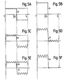
- the results, obtained with the use of a Hilbert filter on the one side and with the use of two filters with an orthogonal pulse response on the other side, can be compared with reference to Figures 5A-5F.
- Figure 5A shows the ideal amplitude frequency characteristic 10 in the interval [0, f s] of a digital filter, used to obtain from a signal f(t) the orthogonal component g(t) thereof, i.e. the Hilbert transform of f(t), where Figure 5B illustrates the ideal characteristic for the f(t)+jg(t) signal.
- the ideal Hilbert filter is of infinite length; the filter used in practice, however, is a non-recursive FIR filter having a limited delay circuit. In such a case, the amplitude-frequency characteristic of the filter is as shown in Figure 5c, by the numeral 12.
- these filters also consist of a non-recursive FIR filter, they also show a ripple depending on the length of the delay circuit; the ripples are however adapted to each other to a high degree, at any rate around the frequency values Hs and;fs and in such a way that the characteristic of thef(t)+jg(t) signal, as indicated in Figure 5E by the numeral 16, shows a practically rippleless stop band, implying a great mutual orthogonality between the f(t) and g(t) signals.
- the embodiments of Figures 6-8 all represent a pulse compression filter, where the input signal is correlated with the two orthogonal components I R , Q R of the replica R of the transmitter pulse.
- the I R and Q R components can be established by a single calculation, and therefore supplied separately to the pulse compression filter, as shown in the embodiment of Figure 6, as well as entered in memory means forming part of the pulse compression filter, as indicated by the embodiments of Figures 7 and 8.
- Separate filters for obtaining the orthogonal components of signal R are not required in these embodiments; the pulse compression filter here consists only of a time-correlation circuit.
- this circuit may consist of two separate non-recursive FIR filters it is of greater advantage to combine these two filters to form one single non-recursive FIR filter and to accomplish the working of two filters by correct timing. Therefore, in the embodiments depicted in Figures 6-8 the pulse compression filter consists of one single non-recursive FIR filter.
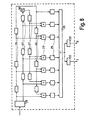
- the pulse compression filter of Figure 6 comprises a delay circuit consisting of N elements 17. Each of the N+1 tappings of this delay circuit is connected to a corresponding multiplying circuit 18. Each of the multiplying circuits 18 is supplied with a certain digital number through the switch 19. These numbers represent either the value of the I R component, or the value of the Q R component. Switch 19 is operated at a frequency twice as large as the shifting frequency of the signals through the delay circuit; i.e. the pulse repetition frequency of the radar or sonar transmitting and receiving unit. This is to achieve that all signals of the tappings are multiplied both by a series of numbers, representing the value of the I R component, and by a series of numbers representing the value of the QR component.
- N is chosen to be divisible by 4, then: A similar relationship is obtained when the frequency modulation is not linear in time; in such a case, the deviation from the linearity should however be skew-symmetric with respect to the frequency f o .
- the latter relationship offers the possibility to simplify the embodiment of the pulse compression filter in Figure 6 to the embodiment shown in Figure 7.
- the embodiment of Figure 7 comprises a delay circuit consisting of N elements.
- the outputs of adder 23 and subtractor 24 are connected to multipliers 25.
- the tapping 1/2N is directly coupled to a corresponding multiplier.
- the numbers forming the I R and Q, signals to multiply the output signals of the adder and the subtractor are here already incorporated permanently in the multipliers, or the multipliers contain memory means for storing these numbers.
- the number of multipliers is then practically halved with respect to the number in the embodiment of Figure 6.
- the operation of the embodiment of Figure 7 is otherwise identical to that in Figure 6.
- a further simplification is provided in the embodiment of Figure 8.
- the delay circuit is built up of two simultaneously active parts, comprising delay elements 26 and 27.
- the number of delay elements in each of the parts is zN.
- This division into two separate series of signal samples enables to supply the signals from the tappings of the two delay circuit parts to adders 29 only, as distinct from the embodiment of Figure 7.
Claims (8)
Applications Claiming Priority (2)
| Application Number | Priority Date | Filing Date | Title |
|---|---|---|---|
| NL8304210A NL8304210A (nl) | 1983-12-07 | 1983-12-07 | Digitaal impulscompressiefilter. |
| NL8304210 | 1983-12-07 |
Publications (3)
| Publication Number | Publication Date |
|---|---|
| EP0145056A2 EP0145056A2 (fr) | 1985-06-19 |
| EP0145056A3 EP0145056A3 (en) | 1985-07-24 |
| EP0145056B1 true EP0145056B1 (fr) | 1989-03-01 |
Family
ID=19842844
Family Applications (1)
| Application Number | Title | Priority Date | Filing Date |
|---|---|---|---|
| EP84201607A Expired EP0145056B1 (fr) | 1983-12-07 | 1984-11-08 | Filtre digital de compression d'impulsions |
Country Status (6)
| Country | Link |
|---|---|
| US (1) | US4673941A (fr) |
| EP (1) | EP0145056B1 (fr) |
| JP (1) | JPS60200185A (fr) |
| CA (1) | CA1208307A (fr) |
| DE (1) | DE3476923D1 (fr) |
| NL (1) | NL8304210A (fr) |
Families Citing this family (14)
| Publication number | Priority date | Publication date | Assignee | Title |
|---|---|---|---|---|
| FR2714481B1 (fr) | 1985-01-08 | 1996-02-23 | Thomson Csf | Procédé de démodulation amplitude phase d'un signal de réception radar et dispositif permettant de mettre en Óoeuvre un tel procédé. |
| US4768156A (en) * | 1986-05-06 | 1988-08-30 | The United States Of America As Represented By The Secretary Of The Navy | Imaging system |
| EP0472024A3 (en) * | 1990-08-24 | 1992-08-19 | Siemens Aktiengesellschaft | Pulse radar system |
| FR2691812B1 (fr) * | 1992-05-29 | 1994-09-02 | Geophysique Cie Gle | Procédé de traitement de signaux pour prospection géophysique exploitant un opérateur d'extrapolation d'un champ d'onde perfectionné. |
| GB9927462D0 (en) * | 1999-11-22 | 2000-01-19 | Systems Engineering & Assessme | Signal processing apparatus |
| US7443337B2 (en) * | 2006-09-25 | 2008-10-28 | Aai Corporation | Synthesizing arbitrary waveforms using convolution processors |
| CN101776747B (zh) * | 2010-01-15 | 2012-07-18 | 山东大学 | 基于自适应重采样的雷达信号压缩方法 |
| RU2012102842A (ru) | 2012-01-27 | 2013-08-10 | ЭлЭсАй Корпорейшн | Инкрементное обнаружение преамбулы |
| KR102015680B1 (ko) * | 2011-10-27 | 2019-08-28 | 인텔 코포레이션 | 최대 가능도 비트-스트림 엔코딩을 이용한 직접 디지털 합성 |
| PL222895B1 (pl) * | 2013-02-07 | 2016-09-30 | Bumar Elektronika Spółka Akcyjna | Sposób i układ kompresji sygnału radarowego |
| US9507017B2 (en) * | 2013-03-15 | 2016-11-29 | Src, Inc. | Simultaneous multi-frequency signal processing method |
| US9923595B2 (en) | 2013-04-17 | 2018-03-20 | Intel Corporation | Digital predistortion for dual-band power amplifiers |
| US9813223B2 (en) | 2013-04-17 | 2017-11-07 | Intel Corporation | Non-linear modeling of a physical system using direct optimization of look-up table values |
| US10677901B2 (en) * | 2016-04-08 | 2020-06-09 | Samsung Medison Co., Ltd. | Ultrasound diagnosis apparatus and method of operating the ultrasound diagnosis apparatus |
Citations (1)
| Publication number | Priority date | Publication date | Assignee | Title |
|---|---|---|---|---|
| US4566010A (en) * | 1982-04-28 | 1986-01-21 | Raytheon Company | Processing arrangement for pulse compression radar |
Family Cites Families (8)
| Publication number | Priority date | Publication date | Assignee | Title |
|---|---|---|---|---|
| US3156914A (en) * | 1960-04-29 | 1964-11-10 | Raytheon Co | Transmission and reception of radar signals |
| FR1287403A (fr) * | 1960-12-30 | 1962-03-16 | Snecma | Dispositif d'élaboration et d'exploitation de signaux et son application aux radarsà grande portée |
| DE1247421B (de) * | 1964-10-17 | 1967-08-17 | Telefunken Patent | Verfahren zur Impulskompression von Radarimpulsen und Anordnung zur Durchfuehrung des Verfahrens |
| US4028700A (en) * | 1972-11-16 | 1977-06-07 | Raytheon Company | Pulse compression radar and method of operating such a radar |
| FR2374651A1 (fr) * | 1976-12-16 | 1978-07-13 | Labo Cent Telecommunicat | Dispositif d'elimination des lobes secondaires d'auto-correlation d'un signal continu periodique code en phase |
| SE426010B (sv) * | 1981-03-20 | 1982-12-06 | Bert Persson | Sett for bekempning av skadeinsekter |
| US4416016A (en) * | 1981-06-11 | 1983-11-15 | Bell Telephone Laboratories, Incorporated | Differential phase shift keyed receiver |
| US4591857A (en) * | 1983-07-11 | 1986-05-27 | The United States Of America As Represented By The Secretary Of The Air Force | Programmable LFM signal processor |
-
1983
- 1983-12-07 NL NL8304210A patent/NL8304210A/nl not_active Application Discontinuation
-
1984
- 1984-11-08 EP EP84201607A patent/EP0145056B1/fr not_active Expired
- 1984-11-08 DE DE8484201607T patent/DE3476923D1/de not_active Expired
- 1984-11-19 US US06/672,517 patent/US4673941A/en not_active Expired - Fee Related
- 1984-11-20 CA CA000468210A patent/CA1208307A/fr not_active Expired
- 1984-12-05 JP JP59255818A patent/JPS60200185A/ja active Granted
Patent Citations (1)
| Publication number | Priority date | Publication date | Assignee | Title |
|---|---|---|---|---|
| US4566010A (en) * | 1982-04-28 | 1986-01-21 | Raytheon Company | Processing arrangement for pulse compression radar |
Also Published As
| Publication number | Publication date |
|---|---|
| DE3476923D1 (en) | 1989-04-06 |
| NL8304210A (nl) | 1985-07-01 |
| JPH0346077B2 (fr) | 1991-07-15 |
| EP0145056A2 (fr) | 1985-06-19 |
| US4673941A (en) | 1987-06-16 |
| EP0145056A3 (en) | 1985-07-24 |
| JPS60200185A (ja) | 1985-10-09 |
| CA1208307A (fr) | 1986-07-22 |
Similar Documents
| Publication | Publication Date | Title |
|---|---|---|
| EP0145056B1 (fr) | Filtre digital de compression d'impulsions | |
| US4384291A (en) | Efficient low-sidelobe pulse compression | |
| US4404562A (en) | Low sidelobe linear FM chirp system | |
| US4379295A (en) | Low sidelobe pulse compressor | |
| US4359736A (en) | Frequency-phase coding device | |
| KR980012873A (ko) | 스펙트럼 직접 확산 신호 수신 장치 및 동기 포착 회로 | |
| US5194870A (en) | Radar receiver | |
| CA1115355A (fr) | Filtre transversal binaire | |
| US4761795A (en) | Receiver for bandspread signals | |
| US4723125A (en) | Device for calculating a discrete moving window transform and application thereof to a radar system | |
| US6208285B1 (en) | Pulse compressor for doppler tolerant radar | |
| US5568150A (en) | Method and apparatus for hybrid analog-digital pulse compression | |
| EP0409538B1 (fr) | Démodulateur pour signal à spectre étalé | |
| WO1992004783A1 (fr) | Procede de reconnaissance de la derive de la frequence lors de la transmission numerique d'information | |
| US4532603A (en) | Chirp transform correlator | |
| US4359735A (en) | Multi-sampling-channel pulse compressor | |
| Sussman | A matched filter communication system for multipath channels | |
| US4779054A (en) | Digital inphase/quadrature product detector | |
| US4167737A (en) | Hybrid pulse compression system | |
| GB2176362A (en) | Digital mixing apparatus | |
| US5661487A (en) | Digital center line filter | |
| US5148127A (en) | Biphase shift keying modulation circuit having constant envelope characteristics | |
| US4344040A (en) | Method and apparatus for providing the in-phase and quadrature components of a bandpass signal | |
| JPS587935A (ja) | トランスバーサル形スミアデスミアフイルタ | |
| RU2207737C1 (ru) | Способ передачи информации и преобразователь последовательности цифровых отсчетов |
Legal Events
| Date | Code | Title | Description |
|---|---|---|---|
| PUAI | Public reference made under article 153(3) epc to a published international application that has entered the european phase |
Free format text: ORIGINAL CODE: 0009012 |
|
| PUAL | Search report despatched |
Free format text: ORIGINAL CODE: 0009013 |
|
| AK | Designated contracting states |
Designated state(s): CH DE FR GB IT LI NL SE |
|
| AK | Designated contracting states |
Designated state(s): CH DE FR GB IT LI NL SE |
|
| 17P | Request for examination filed |
Effective date: 19860109 |
|
| 17Q | First examination report despatched |
Effective date: 19870623 |
|
| GRAA | (expected) grant |
Free format text: ORIGINAL CODE: 0009210 |
|
| AK | Designated contracting states |
Kind code of ref document: B1 Designated state(s): CH DE FR GB IT LI NL SE |
|
| REF | Corresponds to: |
Ref document number: 3476923 Country of ref document: DE Date of ref document: 19890406 |
|
| ET | Fr: translation filed | ||
| ITF | It: translation for a ep patent filed |
Owner name: BARZANO' E ZANARDO ROMA S.P.A. |
|
| PLBE | No opposition filed within time limit |
Free format text: ORIGINAL CODE: 0009261 |
|
| STAA | Information on the status of an ep patent application or granted ep patent |
Free format text: STATUS: NO OPPOSITION FILED WITHIN TIME LIMIT |
|
| 26N | No opposition filed | ||
| NLT1 | Nl: modifications of names registered in virtue of documents presented to the patent office pursuant to art. 16 a, paragraph 1 |
Owner name: HASRODE B.V. TE EINDHOVEN. |
|
| NLS | Nl: assignments of ep-patents |
Owner name: HOLLANDSE SIGNAALAPPARATEN B.V. TE HENGELO (O.). |
|
| REG | Reference to a national code |
Ref country code: GB Ref legal event code: 732 |
|
| REG | Reference to a national code |
Ref country code: FR Ref legal event code: TP Ref country code: FR Ref legal event code: CD Ref country code: FR Ref legal event code: CA |
|
| REG | Reference to a national code |
Ref country code: CH Ref legal event code: PUE Owner name: HOLLANDSE SIGNAALAPPARATEN B.V. Ref country code: CH Ref legal event code: PFA Free format text: HASRODE B.V. |
|
| ITPR | It: changes in ownership of a european patent |
Owner name: CESSIONE;HOLLANDSE SIGNAALAPPARATEN B.V. |
|
| ITTA | It: last paid annual fee | ||
| EAL | Se: european patent in force in sweden |
Ref document number: 84201607.3 |
|
| PGFP | Annual fee paid to national office [announced via postgrant information from national office to epo] |
Ref country code: FR Payment date: 19960930 Year of fee payment: 13 |
|
| PGFP | Annual fee paid to national office [announced via postgrant information from national office to epo] |
Ref country code: SE Payment date: 19961003 Year of fee payment: 13 |
|
| PGFP | Annual fee paid to national office [announced via postgrant information from national office to epo] |
Ref country code: DE Payment date: 19961016 Year of fee payment: 13 Ref country code: CH Payment date: 19961016 Year of fee payment: 13 |
|
| PGFP | Annual fee paid to national office [announced via postgrant information from national office to epo] |
Ref country code: GB Payment date: 19961030 Year of fee payment: 13 |
|
| PGFP | Annual fee paid to national office [announced via postgrant information from national office to epo] |
Ref country code: NL Payment date: 19961111 Year of fee payment: 13 |
|
| PG25 | Lapsed in a contracting state [announced via postgrant information from national office to epo] |
Ref country code: GB Free format text: LAPSE BECAUSE OF NON-PAYMENT OF DUE FEES Effective date: 19971108 |
|
| PG25 | Lapsed in a contracting state [announced via postgrant information from national office to epo] |
Ref country code: SE Free format text: LAPSE BECAUSE OF NON-PAYMENT OF DUE FEES Effective date: 19971109 |
|
| PG25 | Lapsed in a contracting state [announced via postgrant information from national office to epo] |
Ref country code: LI Free format text: LAPSE BECAUSE OF NON-PAYMENT OF DUE FEES Effective date: 19971130 Ref country code: FR Free format text: THE PATENT HAS BEEN ANNULLED BY A DECISION OF A NATIONAL AUTHORITY Effective date: 19971130 Ref country code: CH Free format text: LAPSE BECAUSE OF NON-PAYMENT OF DUE FEES Effective date: 19971130 |
|
| PG25 | Lapsed in a contracting state [announced via postgrant information from national office to epo] |
Ref country code: NL Free format text: LAPSE BECAUSE OF NON-PAYMENT OF DUE FEES Effective date: 19980601 |
|
| GBPC | Gb: european patent ceased through non-payment of renewal fee |
Effective date: 19971108 |
|
| REG | Reference to a national code |
Ref country code: CH Ref legal event code: PL |
|
| PG25 | Lapsed in a contracting state [announced via postgrant information from national office to epo] |
Ref country code: DE Free format text: LAPSE BECAUSE OF NON-PAYMENT OF DUE FEES Effective date: 19980801 |
|
| EUG | Se: european patent has lapsed |
Ref document number: 84201607.3 |
|
| NLV4 | Nl: lapsed or anulled due to non-payment of the annual fee |
Effective date: 19980601 |
|
| REG | Reference to a national code |
Ref country code: FR Ref legal event code: ST |