EP0145012A2 - Water outlet - Google Patents
Water outlet Download PDFInfo
- Publication number
- EP0145012A2 EP0145012A2 EP84115178A EP84115178A EP0145012A2 EP 0145012 A2 EP0145012 A2 EP 0145012A2 EP 84115178 A EP84115178 A EP 84115178A EP 84115178 A EP84115178 A EP 84115178A EP 0145012 A2 EP0145012 A2 EP 0145012A2
- Authority
- EP
- European Patent Office
- Prior art keywords
- ring
- water inlet
- inlet
- face
- plastic
- Prior art date
- Legal status (The legal status is an assumption and is not a legal conclusion. Google has not performed a legal analysis and makes no representation as to the accuracy of the status listed.)
- Granted
Links
- XLYOFNOQVPJJNP-UHFFFAOYSA-N water Substances O XLYOFNOQVPJJNP-UHFFFAOYSA-N 0.000 title claims abstract description 37
- 239000004033 plastic Substances 0.000 claims abstract description 19
- 239000011888 foil Substances 0.000 claims abstract description 13
- 238000007789 sealing Methods 0.000 claims description 6
- 239000004020 conductor Substances 0.000 claims description 4
- 238000010438 heat treatment Methods 0.000 claims description 4
- 238000004519 manufacturing process Methods 0.000 abstract description 3
- 238000005187 foaming Methods 0.000 description 3
- 239000000463 material Substances 0.000 description 3
- 239000002984 plastic foam Substances 0.000 description 3
- 238000004873 anchoring Methods 0.000 description 2
- 239000006260 foam Substances 0.000 description 2
- 238000000465 moulding Methods 0.000 description 2
- 238000005507 spraying Methods 0.000 description 2
- 238000010521 absorption reaction Methods 0.000 description 1
- 230000000295 complement effect Effects 0.000 description 1
- 238000010276 construction Methods 0.000 description 1
- 238000006073 displacement reaction Methods 0.000 description 1
- 238000003780 insertion Methods 0.000 description 1
- 230000037431 insertion Effects 0.000 description 1
- 238000000034 method Methods 0.000 description 1
- 230000000284 resting effect Effects 0.000 description 1
- 238000007493 shaping process Methods 0.000 description 1
Images


Classifications
-
- E—FIXED CONSTRUCTIONS
- E04—BUILDING
- E04D—ROOF COVERINGS; SKY-LIGHTS; GUTTERS; ROOF-WORKING TOOLS
- E04D13/00—Special arrangements or devices in connection with roof coverings; Protection against birds; Roof drainage ; Sky-lights
- E04D13/04—Roof drainage; Drainage fittings in flat roofs, balconies or the like
- E04D13/0404—Drainage on the roof surface
- E04D13/0409—Drainage outlets, e.g. gullies
- E04D2013/0413—Strainers for drainage outlets
-
- E—FIXED CONSTRUCTIONS
- E04—BUILDING
- E04D—ROOF COVERINGS; SKY-LIGHTS; GUTTERS; ROOF-WORKING TOOLS
- E04D13/00—Special arrangements or devices in connection with roof coverings; Protection against birds; Roof drainage ; Sky-lights
- E04D13/04—Roof drainage; Drainage fittings in flat roofs, balconies or the like
- E04D13/0404—Drainage on the roof surface
- E04D13/0409—Drainage outlets, e.g. gullies
- E04D2013/0418—Drainage outlets, e.g. gullies with de-icing devices or snow melters
-
- E—FIXED CONSTRUCTIONS
- E04—BUILDING
- E04D—ROOF COVERINGS; SKY-LIGHTS; GUTTERS; ROOF-WORKING TOOLS
- E04D13/00—Special arrangements or devices in connection with roof coverings; Protection against birds; Roof drainage ; Sky-lights
- E04D13/04—Roof drainage; Drainage fittings in flat roofs, balconies or the like
- E04D13/0404—Drainage on the roof surface
- E04D13/0409—Drainage outlets, e.g. gullies
- E04D2013/0436—Drainage outlets, e.g. gullies with sealing means
- E04D2013/044—Drainage outlets, e.g. gullies with sealing means on multiple levels
Definitions
- the invention relates to a water inlet for flat roofs, consisting of a one-piece component made of a funnel-shaped inlet body, which contains a plastic ring, on the outer circumference of which a connecting foil forming a collar ends.
- a water inlet which consists of two parts, namely on the one hand an inlet body, on the other hand an integral unit made of a plastic ring and a connecting film.
- This unit can be connected to the inlet body via cams provided on the plastic ring, which cooperate with grooves in the inside wall of the inlet body in the manner of a bayonet lock.
- a water inlet constructed in two parts in the same way is also known from DE-OS 26 12 684, however, in order to connect the unit consisting of a plastic ring and a connecting foil to the inlet body, the plastic ring designed as a seal and correspondingly profiled is form-fitting on the inlet body provided with a complementary profile pressed on.
- the water inlet of the water inlet mentioned in the introduction does not have these disadvantages, but one is preferred for its manufacture
- Shaped connecting foil is required, the circular opening of which is kept open during the shaping of the inlet body by spraying, pouring or foaming by means of the plastic ring designed as an expansion ring in such a way that the ring and the subsequent region of the connecting foil are completely embedded in the material of the inlet body after completion of the water inlet are.
- connection film blanks In addition to the disadvantage of not being able to use smooth, flat-lying connection film blanks, it is difficult, if not impossible, to position the plastic ring and the part of the connection film to be embedded in the mold cavity of the tool for producing the water inlet and during the spraying , Pouring or foaming so that the desired embedment depth and a central position of the plastic ring to the axis of the water inlet are maintained.
- a relatively high strength plastic must be used for the inlet body if - as usual - inlet sieves or extension elements are to be anchored sufficiently securely on the inner wall of the water inlet.
- the invention has for its object to design a water inlet of the type specified in the introduction so that it can be produced in a time-saving manner from the simplest possible parts.
- the inlet body is formed on the underside of the connection film and the outside of the ring, that the top of the connection film and the upper end face of the ring lie in one plane, that the connection film in a groove in the outer circumference of the ring close whose upper end surface ends, and that the inner surface of the ring forms the inlet-side, first section of the inner wall of the water inlet.
- This embodiment has the advantage that the plastic ring and thus also the connection film, which is only loosely attached to it, are positioned centrally by the core of the molding tool, the later upper end face of the ring and the later upper side of the connection film resting against one end wall of the mold cavity can. Even if high pressures occur during the subsequent molding of the inlet body, as is the case with the foaming process that is preferably used, no more displacements can occur.
- the ring consists of a plastic of higher strength than the inlet body and has in its inner surface an inwardly opening, circumferential groove which is connected to the upper end face of the ring by way of circular segment-shaped recesses.
- the higher strength of the plastic ring ensures secure anchoring of, for example, an inlet strainer or an extension element.
- the circular segment-shaped recesses and the internal, circumferential groove allow a bayonet-type insertion of such an inlet sieve. Instead, a sealing ring can also be inserted into the groove and then an extension element can be inserted.
- the circular segment-shaped recesses also increase the water absorption capacity of the water inlet.
- the ring advantageously ends on the outlet side in a sealing lip which closes with the inner wall of the inlet body. This prevents the material, eg plastic foam, from getting between the mold core and the plastic ring when the molded body D ers is molded on.
- the ring is provided on its outside with angularly offset webs.
- these can serve for the largely automatic positioning of the connecting foil and the ring in the mold while it is being closed, and on the other hand they improve the anchoring of the ring in the material of the inlet body.
- Another embodiment is characterized in that a support body for an electrical heating conductor is fixed on the outside of the ring in the outlet-side section thereof. With negligible additional effort, this ensures that the heating conductor is molded in a precisely predetermined position.
- the water inlet consists of an inlet body 1, which is connected to a plastic ring 2 and is foamed to a connecting foil '3 in such a way that the upper side of the connecting foil 3 and the upper end face of the ring 2 form a flat connecting flange.
- Fig. 2 illustrates the position of the water inlet before it is removed from the foam mold.
- This consists of a movable molded part 13 and a fixed molded part 14 which is integral with a molded core 14a.
- the ring 2 is provided in its upper, inlet-side part with an outer circumferential groove 4, in which the film 3 ends.
- the ring 2 also has e.g. three webs 8 offset by 120 °.
- the movable molded part 13 presses the inserted ring 2, including the film 3 lying loosely in its groove 4, over these webs 8 into the end position.
- the ring 2 is provided on the inside with a circumferential groove 5, the purpose of which will be explained later.
- the ring 2 ends in a sealing lip 11 which prevents the plastic foam forming the inlet body 1 from getting between the ring 2 and the mold core 14a.
- Fig. 3 shows a second embodiment of the water inlet.
- a sealing ring 9 is additionally inserted, which fixes the film 3 better in the groove 4 and prevents plastic foam from getting between the fixed molded part (14 in FIG. 2) and the film 3.
- a carrier body 19 for a heating conductor 12 is pushed onto the outlet-side end of the ring 2 and is supplied with current via a connection 12a.
- FIG. 4 shows the water inlet according to FIG. 1 in connection with an extension element 20.
- the extension element 20 is constructed in the same way as the water inlet itself.
- An O-ring 6 is inserted into the inner circumferential groove 5 for sealing.
- FIG. 5 illustrates the water inlet according to FIGS. 1 and 2 in two different partial longitudinal sections.
- recesses 7 in the form of segments of a circle are provided on the ring 2, via which the inner groove 5 is connected to the inlet cross section with a smooth surface.
- three such circular segment-shaped recesses 7 offset by 120 ° can be provided.
- an inlet screen 15 can be used with, for example, three feet 16 in the ring 2 and thus in the water inlet and secure by twisting by a certain angle in such a way that the outwardly facing projections of the feet 16 then into the groove 5 come to rest according to the position shown on the right in FIG. 5.
- the inlet sieve 15 is secured against inadvertent rotation by, for example, three recesses 17, each offset by 120 °, the lateral surfaces 18 of which act as stops for the feet 16.
Landscapes
- Engineering & Computer Science (AREA)
- Architecture (AREA)
- Civil Engineering (AREA)
- Structural Engineering (AREA)
- Moulds For Moulding Plastics Or The Like (AREA)
- Supports For Pipes And Cables (AREA)
- Domestic Plumbing Installations (AREA)
- Containers And Packaging Bodies Having A Special Means To Remove Contents (AREA)
- External Artificial Organs (AREA)
Abstract
Description
Die Erfindung betrifft einen Wassereinlauf für Flachdächer, bestehend aus einem einstückigen Bauteil aus einem trichterförmigen Einlaufkörper, der einen Kunststoffring enthält, an dessen Außenumfang eine einen Kragen bildende Anschlußfolie endet.The invention relates to a water inlet for flat roofs, consisting of a one-piece component made of a funnel-shaped inlet body, which contains a plastic ring, on the outer circumference of which a connecting foil forming a collar ends.
Aus der DE-AS 24 22 658 ist ein Wassereinlauf bekannt, der aus zwei Teilen besteht, nämlich einerseits einem Einlaufkörper, andererseits einer einstückigen Einheit aus einem Kunststoffring und einer Anschlußfolie. Diese Einheit ist mit dem Einlaufkörper über an dem Kunststoffring vorgesehene Nocken, die mit in der Innenwand des Einlaufkörpers vorhanden Nuten nach Art eines BajonettVerschlusses zusammenwirken, verbindbar. Ein in gleicher Weise zweiteilig aufgebauter Wassereinlauf ist auch aus der DE-OS 26 12 684 bekannt, jedoch wird hierbei zur Verbindung der Einheit aus Kunststoffring und Anschlußfolie mit dem Einlaufkörper der als Dichtung ausgestaltete und entsprechend profilierte Kunststoffring formschlüssig auf den mit einem komplementären Profil versehenen Einlaufkörper aufgedrückt. Beiden bekannten Wassereinläufen ist der Nachteil gemeinsam, daß der Einlaufkörper einerseits und die Einheit aus Kunststoffring und Anschlußfolie andererseits in getrennten Formen hergestellt und auf Lager gehalten werden müssen. Zudem ist eine dauerhaft dichte Verbindung zwischen den getrennten Konstruktionsteilen nicht gewährleistet.From DE-AS 24 22 658 a water inlet is known, which consists of two parts, namely on the one hand an inlet body, on the other hand an integral unit made of a plastic ring and a connecting film. This unit can be connected to the inlet body via cams provided on the plastic ring, which cooperate with grooves in the inside wall of the inlet body in the manner of a bayonet lock. A water inlet constructed in two parts in the same way is also known from DE-OS 26 12 684, however, in order to connect the unit consisting of a plastic ring and a connecting foil to the inlet body, the plastic ring designed as a seal and correspondingly profiled is form-fitting on the inlet body provided with a complementary profile pressed on. The disadvantage of both known water inlets is that the inlet body, on the one hand, and the unit made of plastic ring and connecting film, on the other hand, have to be manufactured in separate molds and kept in stock. In addition, a permanently tight connection between the separate construction parts is not guaranteed.
Diese Nachteile weist der Wassereinlauf der einleitend angegebenen, aus dem DE-GM 77 03 110 bekannte Wassereinlauf nicht auf, jedoch wird für dessen Herstellung eine vorgeformte Anschlußfolie benötigt, deren kreisförmige Öffnung während der Formung des Einlaufkörpers durch Spritzen, Gießen oder Schäumen mittels des als Spreizring ausgebildeten Kunststoffringes in der Weise offengehalten wird, daß der Ring und der anschließende Bereich der Anschlußfolie nach Fertigstellung des Wassereinlaufes vollständig in das Material des Einlaufkörpers eingebettet sind. Zu dem Nachteil, keine glatten, flachliegenden Anschlußfolienzuschnitte verwenden zu können, kommt hinzu, daß es schwierig, wenn nicht sogar unmöglich ist, den Kunststoffring und den einzubettenden Teil der Anschlußfolie in dem Formhohlraum des Werkzeuges zur Herstellung des Wassereinlaufes so zu positionieren und während des Spritzens, Gießens oder Schäumens so positioniert zu erhalten, daß die gewünschte Einbettungstiefe und eine zentrische Lage des Kunststoffringes zu der Achse des Wassereinlaufs eingehalten werden. Außerdem muß für den Einlaufkörper ein Kunststoff verhältnismäßig hoher Festigkeit verwendet werden, wenn an der Innenwand des Wassereinlaufes - wie üblich - Einlaufsiebe oder Aufstockelemente hinreichend sicher verankert werden sollen.The water inlet of the water inlet mentioned in the introduction, known from DE-GM 77 03 110, does not have these disadvantages, but one is preferred for its manufacture Shaped connecting foil is required, the circular opening of which is kept open during the shaping of the inlet body by spraying, pouring or foaming by means of the plastic ring designed as an expansion ring in such a way that the ring and the subsequent region of the connecting foil are completely embedded in the material of the inlet body after completion of the water inlet are. In addition to the disadvantage of not being able to use smooth, flat-lying connection film blanks, it is difficult, if not impossible, to position the plastic ring and the part of the connection film to be embedded in the mold cavity of the tool for producing the water inlet and during the spraying , Pouring or foaming so that the desired embedment depth and a central position of the plastic ring to the axis of the water inlet are maintained. In addition, a relatively high strength plastic must be used for the inlet body if - as usual - inlet sieves or extension elements are to be anchored sufficiently securely on the inner wall of the water inlet.
Der Erfindung liegt die Aufgabe zugrunde, einen Wassereinlauf der einleitend angegebenen Gattung so auszubilden, daß er sich aus möglichst einfach geformten Teilen zeitsparend herstellen läßt.The invention has for its object to design a water inlet of the type specified in the introduction so that it can be produced in a time-saving manner from the simplest possible parts.
Diese Aufgabe ist erfindungsgemäß dadurch gelöst, daß der Einlaufkörper an die Unterseite der Anschlußfolie und die Außenseite des Ringes angeformt ist, daß die Oberseite der Anschlußfolie und die obere Stirnfläche des Ringes in einer Ebene liegen, daß die Anschlußfolie in einer Nut im Außenumfang des Ringes nahe dessen oberer Stirnfläche endet, und daß die Innenfläche des Ringes den einlaufseitigen,ersten Abschnitt der Innenwand des Wassereinlautes bildet.This object is achieved in that the inlet body is formed on the underside of the connection film and the outside of the ring, that the top of the connection film and the upper end face of the ring lie in one plane, that the connection film in a groove in the outer circumference of the ring close whose upper end surface ends, and that the inner surface of the ring forms the inlet-side, first section of the inner wall of the water inlet.
Diese Ausgestaltung hat den Vorteil, daß der Kunststoffring und damit auch die an ihm gegebenenfalls nur lose festgelegte Anschlußfolie durch den Kern des Formwerkzeuges zentrisch positioniert werden, wobei sich die spätere obere Stirnseite des Ringes und die spätere Oberseite der Anschlußfolie an die eine Stirnwand des Formhohlraumes anlegen können. Auch wenn beim nachfolgenden Anformen des Einlaufkörpers hohe Drucke auftreten, wie dies bei dem bevorzugt angewendeten Schäumverfahren der Fall ist, können keine Verschiebungen mehr eintreten.This embodiment has the advantage that the plastic ring and thus also the connection film, which is only loosely attached to it, are positioned centrally by the core of the molding tool, the later upper end face of the ring and the later upper side of the connection film resting against one end wall of the mold cavity can. Even if high pressures occur during the subsequent molding of the inlet body, as is the case with the foaming process that is preferably used, no more displacements can occur.
Bei einer bevorzugten Ausführungsform besteht der Ring aus einem Kunststoff höherer Festigkeit als der Einlaufkörper und hat in seiner Innenfläche eine sich nach innen öffnende, umlaufende Nut, die über kreissegmentförmige Ausnehmungen mit der oberen Stirnfläche des Ringes in Verbindung steht. Die höhere Festigkeit des Kunststoffringes gewährleistet eine sichere Verankerung beispielsweise eines Einlaufsiebes oder eines Aufstockelementes. Die kreissegmentförmigen Ausnehmungen und die innenliegende, umlaufende Nut erlauben ein bajonettverschlußartiges Einsetzen eines solchen Einlaufsiebes. Stattdessen kann in die Nut auch ein Dichtungsring eingelegt und anschließend ein Aufstockelement eingesetzt werden. Die kreissegmentförmigen Ausnehmungen erhöhen außerdem das Wasserschluckvermögen des Wassereinlaufes.In a preferred embodiment, the ring consists of a plastic of higher strength than the inlet body and has in its inner surface an inwardly opening, circumferential groove which is connected to the upper end face of the ring by way of circular segment-shaped recesses. The higher strength of the plastic ring ensures secure anchoring of, for example, an inlet strainer or an extension element. The circular segment-shaped recesses and the internal, circumferential groove allow a bayonet-type insertion of such an inlet sieve. Instead, a sealing ring can also be inserted into the groove and then an extension element can be inserted. The circular segment-shaped recesses also increase the water absorption capacity of the water inlet.
Mit Vorteil endet der Ring auslaufseitig in einer mit der Innenwand des Einlaufkörpers abschließenden Dichtlippe. Diese verhindert, daß beim Anformen des Form- körDers dessen Material, z.B. Kunststoffschaum, zwischen den Formkern und den Kunststoffring gelangt.The ring advantageously ends on the outlet side in a sealing lip which closes with the inner wall of the inlet body. This prevents the material, eg plastic foam, from getting between the mold core and the plastic ring when the molded body D ers is molded on.
Eine weitere bevorzugte Ausführungsform besteht darin, daß der Ring an seiner Außenseite mit winkelmäßig versetzt angeordneten Stegen versehen ist.Another preferred embodiment is that the ring is provided on its outside with angularly offset webs.
Diese können einerseits zurweitgehend selbsttätigen Positionierung der Anschlußfolie und des Ringes in der Werkzeugform während deren Schließens dienen und verbessern andererseits die Verankerung des Ringes in dem Material des Einlaufkörpers.On the one hand, these can serve for the largely automatic positioning of the connecting foil and the ring in the mold while it is being closed, and on the other hand they improve the anchoring of the ring in the material of the inlet body.
Eine weitere Ausführungsform zeichnet sich dadurch aus, daß an der Außenseite des Ringes in dessen auslaufseitigem Abschnitt ein Trägerkörper für einen elektrischen Heizleiter festgelegt ist. Mit vernachlässigbarem zusätzlichem Aufwand wird hierdurch eine Einformung des Heizleiters in genau vorgegebener Lage sichergestellt.Another embodiment is characterized in that a support body for an electrical heating conductor is fixed on the outside of the ring in the outlet-side section thereof. With negligible additional effort, this ensures that the heating conductor is molded in a precisely predetermined position.
In der Zeichnung ist ein Wassereinlauf nach der Erfindung in beispielsweise gewählten Ausführungsformen schematisch vereinfacht dargestellt.In the drawing, a water inlet according to the invention is shown schematically simplified in, for example, selected embodiments.
Es zeigt:
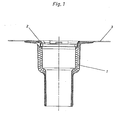
- Fig. 1 den Wassereinlauf im Längsschnitt,
- Fig. 2 einen vergrößerten Teilschnitt durch den Wassereinlauf und das Formwerkzeug zu seiner Herstellung,
- Fig. 3 eine zweite Ausführungsform des Wassereinlaufes im vergrößerten Teilschnitt,
- Fig. 4 einen Schnitt durch den Wassereinlauf nach Fig. 1 mit eingesetztem Aufstockelement und
- Fig. 5 den Wassereinlauf nach Fig. 1 in zwei verschiedenen Teillängsschnltten.
- 1 shows the water inlet in longitudinal section,
- 2 is an enlarged partial section through the water inlet and the mold for its manufacture,
- 3 shows a second embodiment of the water inlet in an enlarged partial section,
- Fig. 4 shows a section through the water inlet according to Fig. 1 with an extension element and
- Fig. 5 shows the water inlet according to Fig. 1 in two different partial longitudinal sections.
Gemäß Fig. 1 besteht der Wassereinlauf aus einem Einlaufkörper 1 , der an einen Kunststoffring 2 und an eine Anschlußfolie '3 derart angeschäumt ist, daß die Oberseite der Anschlußfolie 3 und die obere Stirnfläche des Ringes 2. einen planen Anschlußflansch bilden.1, the water inlet consists of an
Fig. 2 veranschaulicht die Lage des Wassereinlaufes vor seiner Entformung aus der Schäumform. Diese besteht aus einem beweglichen Formteil 13 und einem feststehenden Formteil 14 , daseinstückig mit einem Formkern 14a ist. Der Ring 2 ist in seinem oberen, einlaufseitigen Teil mit einer außenliegenden Umfangsnut 4 versehen, in der die Folie 3 endet. Der Ring 2 hat weiterhin außenseitig z.B. drei um 120° versetzt angeordnete Stege 8 . Das bewegliche Formteil 13 drückt beim Schließen der Schäumform den eingelegten Ring 2 einschließlich der lose in seiner Nut 4 liegenden Folie 3 über diese Stege 8 in die Endlage. Der Ring 2 ist innenseitig mit einer umlaufenden Nut 5 versehen, deren Zweck später noch erläutert werden wird. Auslaufseitig endet der Ring 2 in einer Dichtlippe 11 , die verhindert, daß der den Einlaufkörper 1 bildende Kunststoffschaum zwischen den Ring 2 und den Formkern 14a gelangt.Fig. 2 illustrates the position of the water inlet before it is removed from the foam mold. This consists of a movable molded
Fig. 3 zeigt eine zweite Ausführungsform des Wassereinlaufes. In die außenliegende, umlaufende Nut 4 ist zusätzlich ein Dichtring 9 eingelegt, der die Folie 3 besser in der Nut 4 fixiert und verhindert, daß Kunststoffschaum zwischen das feststehende Formteil (14 in Fig. 2) und die Folie 3 gelangt. Auf das auslaufseitige Ende des Ringes 2 ist ein Trägerkörper 19 für einen Heizleiter 12 aufgeschoben, der über einen Anschluß 12a mit Strom versorgt wird.Fig. 3 shows a second embodiment of the water inlet. In the outer,
Fig. 4 zeigt den Wassereinlauf nach Fig. 1 in Verbindung mit einem Aufstockelement 20 . Das Aufstockelement 20 ist gleichartig wie der Wassereinlauf selbst ausgebildet.FIG. 4 shows the water inlet according to FIG. 1 in connection with an
Zur Abdichtung ist in die innenliegende, umlaufende Nut 5 ein 0-Ring 6 eingelegt.An O-
Fig. 5 veranschaulicht den Wassereinlauf nach den Fig. 1 und 2 in zwei verschiedenen Teillängsschnitten. Wie aus der linken Darstellung ersichtlich, sind an dem Ring 2 kreissegmentförmige Ausnehmungen 7 vorgesehen, über die die innenliegende Nut 5 glattflächig mit dem Einlaufquerschnitt in Verbindung steht. Insbesondere können drei um 120° versetzte derartige kreissegmentförmige Ausnehmungen 7 vorgesehen sein. Über diese kreissegmentförmigen Ausnehmungen 7 läßt sich ein Einlaufsieb 15 mit beispielsweise drei Füßen 16 in den Ring 2 und damit in den Wassereinlauf einsetzen und durch Verdrehen um einen bestimmten Winkel in der Weise sichern, daß die nach außen weisenden Vorsprünge der Füße 16 dann in die Nut 5 gemäß der in Fig. 5 rechts gezeigten Stellung zu liegen kommen. In dieser Stellung ist das Einlaufsieb 15 gegen unbeabsichtigtes Verdrehen durch beispielsweise ebenfalls drei um je 120° versetzt angeordnete Rücksprünge 17 gesichert, deren seitliche Flächen 18 als Anschläge für die Füße 16 wirken.5 illustrates the water inlet according to FIGS. 1 and 2 in two different partial longitudinal sections. As can be seen from the left-hand illustration,
Claims (5)
Priority Applications (1)
| Application Number | Priority Date | Filing Date | Title |
|---|---|---|---|
| AT84115178T ATE61838T1 (en) | 1983-12-13 | 1984-12-11 | WATER INLET. |
Applications Claiming Priority (2)
| Application Number | Priority Date | Filing Date | Title |
|---|---|---|---|
| DE3345083 | 1983-12-13 | ||
| DE3345083 | 1983-12-13 |
Publications (3)
| Publication Number | Publication Date |
|---|---|
| EP0145012A2 true EP0145012A2 (en) | 1985-06-19 |
| EP0145012A3 EP0145012A3 (en) | 1986-12-17 |
| EP0145012B1 EP0145012B1 (en) | 1991-03-20 |
Family
ID=6216836
Family Applications (1)
| Application Number | Title | Priority Date | Filing Date |
|---|---|---|---|
| EP84115178A Expired - Lifetime EP0145012B1 (en) | 1983-12-13 | 1984-12-11 | Water outlet |
Country Status (3)
| Country | Link |
|---|---|
| EP (1) | EP0145012B1 (en) |
| AT (1) | ATE61838T1 (en) |
| DE (1) | DE3484296D1 (en) |
Cited By (4)
| Publication number | Priority date | Publication date | Assignee | Title |
|---|---|---|---|---|
| EP0300963A1 (en) * | 1987-07-24 | 1989-01-25 | Geberit AG | Installation element, in particular for a drain pipe or for a pipe connection |
| GB2331529A (en) * | 1997-11-20 | 1999-05-26 | Dallmer Gmbh & Co | A drain fitting |
| CN113944287A (en) * | 2021-11-15 | 2022-01-18 | 甘肃省集成装配式建筑产业发展有限公司 | Assembled water drainage port with anti-seepage function and construction method thereof |
| EE01567U1 (en) * | 2019-11-21 | 2022-05-16 | Vesivek Tuotteet Oy | A roof drain |
Citations (5)
| Publication number | Priority date | Publication date | Assignee | Title |
|---|---|---|---|---|
| DE2422658B1 (en) * | 1974-05-10 | 1975-04-17 | Klaus Esser Kg, 4041 Norf | Water inlet for draining flat roofs, balconies, terraces or the like |
| DE2422659B1 (en) * | 1974-05-10 | 1975-07-03 | Klaus Esser Kg, 4041 Norf | Electrically heated water drain funnel for flat roofs - has electrical heating conductors on carrier, embedded in foam plastics |
| FR2280761A1 (en) * | 1974-08-01 | 1976-02-27 | Goebel Klaus | WATER DRAINAGE, ESPECIALLY FOR TERRACE ROOFS |
| DE7703110U1 (en) * | 1977-02-03 | 1977-05-12 | Grumbach, Emil, 6331 Muenchholzhausen | ROOF GULLY |
| DE2612684A1 (en) * | 1976-03-25 | 1977-09-29 | Continental Gummi Werke Ag | Gulley seal for joining to flexible sheet - has joining flange and rim with lips engaging with gulley grooves |
-
1984
- 1984-12-11 DE DE8484115178T patent/DE3484296D1/en not_active Expired - Fee Related
- 1984-12-11 EP EP84115178A patent/EP0145012B1/en not_active Expired - Lifetime
- 1984-12-11 AT AT84115178T patent/ATE61838T1/en not_active IP Right Cessation
Patent Citations (5)
| Publication number | Priority date | Publication date | Assignee | Title |
|---|---|---|---|---|
| DE2422658B1 (en) * | 1974-05-10 | 1975-04-17 | Klaus Esser Kg, 4041 Norf | Water inlet for draining flat roofs, balconies, terraces or the like |
| DE2422659B1 (en) * | 1974-05-10 | 1975-07-03 | Klaus Esser Kg, 4041 Norf | Electrically heated water drain funnel for flat roofs - has electrical heating conductors on carrier, embedded in foam plastics |
| FR2280761A1 (en) * | 1974-08-01 | 1976-02-27 | Goebel Klaus | WATER DRAINAGE, ESPECIALLY FOR TERRACE ROOFS |
| DE2612684A1 (en) * | 1976-03-25 | 1977-09-29 | Continental Gummi Werke Ag | Gulley seal for joining to flexible sheet - has joining flange and rim with lips engaging with gulley grooves |
| DE7703110U1 (en) * | 1977-02-03 | 1977-05-12 | Grumbach, Emil, 6331 Muenchholzhausen | ROOF GULLY |
Cited By (5)
| Publication number | Priority date | Publication date | Assignee | Title |
|---|---|---|---|---|
| EP0300963A1 (en) * | 1987-07-24 | 1989-01-25 | Geberit AG | Installation element, in particular for a drain pipe or for a pipe connection |
| GB2331529A (en) * | 1997-11-20 | 1999-05-26 | Dallmer Gmbh & Co | A drain fitting |
| GB2331529B (en) * | 1997-11-20 | 2002-05-22 | Dallmer Gmbh & Co | Sleeve when used to connect a drain fitting and a pipeline |
| EE01567U1 (en) * | 2019-11-21 | 2022-05-16 | Vesivek Tuotteet Oy | A roof drain |
| CN113944287A (en) * | 2021-11-15 | 2022-01-18 | 甘肃省集成装配式建筑产业发展有限公司 | Assembled water drainage port with anti-seepage function and construction method thereof |
Also Published As
| Publication number | Publication date |
|---|---|
| EP0145012B1 (en) | 1991-03-20 |
| ATE61838T1 (en) | 1991-04-15 |
| DE3484296D1 (en) | 1991-04-25 |
| EP0145012A3 (en) | 1986-12-17 |
Similar Documents
| Publication | Publication Date | Title |
|---|---|---|
| DE2900565A1 (en) | METHOD AND DEVICE FOR TIRE REMOVAL IN SEGMENTED CORES | |
| DE69910180T3 (en) | Molding an elastomeric profile to a windowpane | |
| DE2802237C2 (en) | Injection mold for the production of injection molded parts consisting of at least two different plastic compounds and having at least two different areas | |
| DE3134602C2 (en) | Method and device for producing a tube with a closure cap made of plastic | |
| EP1613453B1 (en) | Method and apparatus for producing a shaft bottom and a set of moulding elements | |
| EP1627716B1 (en) | Forming part for a man hole | |
| DE3107321A1 (en) | STRIPES, IN PARTICULAR SEALING STRIPS, AND MOLD FOR THEIR PRODUCTION | |
| EP0145012B1 (en) | Water outlet | |
| DE3445186C2 (en) | Water inlet | |
| DE2908161A1 (en) | METHOD AND DEVICE FOR THE CONTINUOUS PRODUCTION OF A CYLINDRICAL BLOCK FROM REUSED FOAM MATERIAL | |
| EP0954435B1 (en) | Method for producing a composite bathtub | |
| EP0314160B1 (en) | Casting apparatus for producing cast plastics | |
| DE2804645A1 (en) | PIPE COUPLING | |
| DE3532440A1 (en) | METHOD FOR PRODUCING A SEAL | |
| DE3043275A1 (en) | Injection moulding corrugated thimble shapes - using compressed air when mould opens to inflate moulding and blow off male tool | |
| DE2732866A1 (en) | EXTRUSION PROFILES AND SHAPE HERE | |
| EP0776749B1 (en) | Process for manufacturing multilayered tubs | |
| EP0670395A2 (en) | Lower element for manhole shafts | |
| DE2511302B2 (en) | Process for the production of a shaft seal | |
| EP0755760B1 (en) | Apparatus for making manholes | |
| DE2116677A1 (en) | Plastic closure - prepd by moulding in cavity between three part press plug and die | |
| DE2105086C3 (en) | Forming tool | |
| EP1232050B1 (en) | Lost core method for producing a hollow structure | |
| DE2626183C3 (en) | Method for releasably connecting a container with a smooth body end to a lid used to close the container | |
| AT500886B1 (en) | A method for production of concrete shaft bottom comprising a drain of defined shape , where the concrete is introduced into the bottom mold useful in the production of concrete shafts |
Legal Events
| Date | Code | Title | Description |
|---|---|---|---|
| PUAI | Public reference made under article 153(3) epc to a published international application that has entered the european phase |
Free format text: ORIGINAL CODE: 0009012 |
|
| AK | Designated contracting states |
Designated state(s): AT BE DE FR |
|
| 17P | Request for examination filed |
Effective date: 19851223 |
|
| PUAL | Search report despatched |
Free format text: ORIGINAL CODE: 0009013 |
|
| AK | Designated contracting states |
Kind code of ref document: A3 Designated state(s): AT BE DE FR |
|
| 17Q | First examination report despatched |
Effective date: 19890616 |
|
| GRAA | (expected) grant |
Free format text: ORIGINAL CODE: 0009210 |
|
| AK | Designated contracting states |
Kind code of ref document: B1 Designated state(s): AT BE DE FR |
|
| REF | Corresponds to: |
Ref document number: 61838 Country of ref document: AT Date of ref document: 19910415 Kind code of ref document: T |
|
| REF | Corresponds to: |
Ref document number: 3484296 Country of ref document: DE Date of ref document: 19910425 |
|
| ET | Fr: translation filed | ||
| PLBE | No opposition filed within time limit |
Free format text: ORIGINAL CODE: 0009261 |
|
| STAA | Information on the status of an ep patent application or granted ep patent |
Free format text: STATUS: NO OPPOSITION FILED WITHIN TIME LIMIT |
|
| 26N | No opposition filed | ||
| PGFP | Annual fee paid to national office [announced via postgrant information from national office to epo] |
Ref country code: BE Payment date: 19941128 Year of fee payment: 11 |
|
| PGFP | Annual fee paid to national office [announced via postgrant information from national office to epo] |
Ref country code: FR Payment date: 19941215 Year of fee payment: 11 |
|
| PGFP | Annual fee paid to national office [announced via postgrant information from national office to epo] |
Ref country code: AT Payment date: 19941223 Year of fee payment: 11 |
|
| PG25 | Lapsed in a contracting state [announced via postgrant information from national office to epo] |
Ref country code: AT Effective date: 19951211 |
|
| PG25 | Lapsed in a contracting state [announced via postgrant information from national office to epo] |
Ref country code: BE Effective date: 19951231 |
|
| BERE | Be: lapsed |
Owner name: ETERNIT A.G. Effective date: 19951231 |
|
| PG25 | Lapsed in a contracting state [announced via postgrant information from national office to epo] |
Ref country code: FR Effective date: 19960830 |
|
| REG | Reference to a national code |
Ref country code: FR Ref legal event code: ST |
|
| PGFP | Annual fee paid to national office [announced via postgrant information from national office to epo] |
Ref country code: DE Payment date: 20011213 Year of fee payment: 18 |
|
| PG25 | Lapsed in a contracting state [announced via postgrant information from national office to epo] |
Ref country code: DE Free format text: LAPSE BECAUSE OF NON-PAYMENT OF DUE FEES Effective date: 20030701 |