EP0144461B1 - Method of and circuit arrangement for the recognition of chrominances and colours - Google Patents
Method of and circuit arrangement for the recognition of chrominances and colours Download PDFInfo
- Publication number
- EP0144461B1 EP0144461B1 EP83112577A EP83112577A EP0144461B1 EP 0144461 B1 EP0144461 B1 EP 0144461B1 EP 83112577 A EP83112577 A EP 83112577A EP 83112577 A EP83112577 A EP 83112577A EP 0144461 B1 EP0144461 B1 EP 0144461B1
- Authority
- EP
- European Patent Office
- Prior art keywords
- colour
- signal
- hue
- color
- values
- Prior art date
- Legal status (The legal status is an assumption and is not a legal conclusion. Google has not performed a legal analysis and makes no representation as to the accuracy of the status listed.)
- Expired
Links
- 239000003086 colorant Substances 0.000 title claims abstract description 60
- 238000000034 method Methods 0.000 title claims description 27
- 230000009466 transformation Effects 0.000 claims abstract description 31
- 238000001514 detection method Methods 0.000 claims description 110
- 238000000926 separation method Methods 0.000 claims description 52
- 238000012937 correction Methods 0.000 claims description 36
- 238000005259 measurement Methods 0.000 claims description 30
- 238000007639 printing Methods 0.000 claims description 28
- 230000005693 optoelectronics Effects 0.000 claims description 15
- 238000004519 manufacturing process Methods 0.000 claims description 6
- 238000007493 shaping process Methods 0.000 claims description 4
- 230000003595 spectral effect Effects 0.000 claims description 3
- 235000019642 color hue Nutrition 0.000 claims 3
- 230000000717 retained effect Effects 0.000 claims 2
- 238000011156 evaluation Methods 0.000 claims 1
- 238000005286 illumination Methods 0.000 claims 1
- 230000015572 biosynthetic process Effects 0.000 abstract description 5
- 238000005516 engineering process Methods 0.000 abstract description 4
- 235000019646 color tone Nutrition 0.000 description 57
- 230000008569 process Effects 0.000 description 8
- 238000012544 monitoring process Methods 0.000 description 7
- 230000006870 function Effects 0.000 description 6
- 230000000295 complement effect Effects 0.000 description 5
- 230000001419 dependent effect Effects 0.000 description 4
- 239000004753 textile Substances 0.000 description 2
- 239000000654 additive Substances 0.000 description 1
- 230000000996 additive effect Effects 0.000 description 1
- 230000008901 benefit Effects 0.000 description 1
- 239000000969 carrier Substances 0.000 description 1
- 238000006243 chemical reaction Methods 0.000 description 1
- 230000007423 decrease Effects 0.000 description 1
- 239000000976 ink Substances 0.000 description 1
- 230000007935 neutral effect Effects 0.000 description 1
- 238000004806 packaging method and process Methods 0.000 description 1
- 230000008447 perception Effects 0.000 description 1
- 229910052573 porcelain Inorganic materials 0.000 description 1
- 238000012545 processing Methods 0.000 description 1
- 230000000750 progressive effect Effects 0.000 description 1
- 229920006395 saturated elastomer Polymers 0.000 description 1
- 230000007704 transition Effects 0.000 description 1
Images


Classifications
-
- G—PHYSICS
- G01—MEASURING; TESTING
- G01J—MEASUREMENT OF INTENSITY, VELOCITY, SPECTRAL CONTENT, POLARISATION, PHASE OR PULSE CHARACTERISTICS OF INFRARED, VISIBLE OR ULTRAVIOLET LIGHT; COLORIMETRY; RADIATION PYROMETRY
- G01J3/00—Spectrometry; Spectrophotometry; Monochromators; Measuring colours
- G01J3/46—Measurement of colour; Colour measuring devices, e.g. colorimeters
- G01J3/462—Computing operations in or between colour spaces; Colour management systems
-
- H—ELECTRICITY
- H04—ELECTRIC COMMUNICATION TECHNIQUE
- H04N—PICTORIAL COMMUNICATION, e.g. TELEVISION
- H04N1/00—Scanning, transmission or reproduction of documents or the like, e.g. facsimile transmission; Details thereof
- H04N1/46—Colour picture communication systems
- H04N1/54—Conversion of colour picture signals to a plurality of signals some of which represent particular mixed colours, e.g. for textile printing
-
- G—PHYSICS
- G01—MEASURING; TESTING
- G01J—MEASUREMENT OF INTENSITY, VELOCITY, SPECTRAL CONTENT, POLARISATION, PHASE OR PULSE CHARACTERISTICS OF INFRARED, VISIBLE OR ULTRAVIOLET LIGHT; COLORIMETRY; RADIATION PYROMETRY
- G01J3/00—Spectrometry; Spectrophotometry; Monochromators; Measuring colours
- G01J3/46—Measurement of colour; Colour measuring devices, e.g. colorimeters
- G01J2003/466—Coded colour; Recognition of predetermined colour; Determining proximity to predetermined colour
Abstract
Description
Die Erfindung bezieht sich insbesondere auf das Gebiet der elektronischen Reproduktionstechnik und betrifft ein Verfahren zum Erkennen von Farbtönen und Farben in farbigen Flächen gemäß dem Oberbegriff des Anspruchs 1 sowie eine Schaltungsanordnung.The invention relates in particular to the field of electronic reproduction technology and relates to a method for recognizing color tones and colors in colored areas according to the preamble of claim 1 and a circuit arrangement.
Unter farbigen Flächen sollen beispielsweise Farbvorlagen für die elektronische Reproduktionstechnik, farbige Musterentwürfe zur Gewinnung von Steuerdaten für Textil-Verarbeitungsmaschinen oder farbige Druckträger verstanden werden.Colored areas are to be understood to mean, for example, color templates for electronic reproduction technology, colored sample designs for obtaining control data for textile processing machines, or colored print carriers.
Vor der eigentlichen Farberkennung werden mit Hilfe von Farberkennungs-Schaltungen innerhalb eines Farbraumes Farberkennungsräume um diejenigen Farborte abgegrenzt, deren Farben innerhalb der farbigen Fläche als Einzelfarben erkannt werden sollen. Während der Farberkennung wird die zu analysierende farbige Fläche punkt- und zeilenweise trichromatisch abgetastet und durch optoelektronische Wandlung der Abtastlichtanteile werden Farbsignale gewonnen, welche die Farbkoordinaten der Farborte der abgetasteten Farben in dem Farbraum darstellen. Durch Auswerten der Farbsignale in der Farberkennungs-Schaltung wird dann festgestellt, in welche abgegrenzten Farberkennungsräume die Farborte der abgetasteten Farben fallen, wodurch diese Farben identifiziert sind.Before the actual color detection, color detection circuits within a color space are delimited by those color locations whose colors are to be recognized as individual colors within the colored area. During the color recognition, the colored surface to be analyzed is scanned point by point and line by line, and color signals are obtained by optoelectronic conversion of the scanning light components, which represent the color coordinates of the color locations of the scanned colors in the color space. By evaluating the color signals in the color recognition circuit, it is then determined in which delimited color recognition spaces the color locations of the scanned colors fall, as a result of which these colors are identified.
Solche Farberkennungs-Schaltungen finden in der Reproduktionstechnik z. B. bei der Herstellung von Farbauszügen mittels Farbscanner für den Mehrfarben-Mischdruck oder für den Einzelfarbendruck Anwendung.Such color detection circuits are used in reproduction technology, for. B. in the production of color separations using a color scanner for multi-color mixed printing or for single-color printing application.
Bei der Herstellung von Farbauszügen für den Mehrfarben-Mischdruck werden die durch Abtastung der Farbvorlage gewonnenen Farbsignale durch eine Grund-Farbkorrektur in Farbauszugs-Signale umgewandelt, welche ein Maß für die Stärke des Farbauftrages der Druckfarben Gelb, Magenta, Cyan und Schwarz beim Druckprozeß sind.In the production of color separations for multicolor mixed printing, the color signals obtained by scanning the color template are converted by a basic color correction into color separation signals which are a measure of the strength of the color application of the printing colors yellow, magenta, cyan and black during the printing process.
Durch die Grund-Farbkorrektur werden Farbfehler beseitigt, die sich unter anderem aufgrund der unterschiedlichen spektralen Eigenschaften von Vorlagenfarben und Druckfarben ergeben, und ggf. die redaktionelle gewünschte farbliche Aussage der Reproduktion gegenüber dem Original geändert. Neben der Grund-Farbkorrektur wird häufig eine zusätzliche Selektiv-Farbkorrektur durchgeführt, mit der gezielt ganz bestimmte Farben oder Farbtöne korrigiert werden sollen.The basic color correction eliminates color errors that result, among other things, from the different spectral properties of original colors and printing inks, and, if necessary, changes the editorial desired color statement of the reproduction compared to the original. In addition to the basic color correction, an additional selective color correction is often carried out, with which specific colors or hues are to be corrected in a targeted manner.
Bei der Selektiv-Farbkorrektur besteht dann das Problem, mit Hilfe von Farberkennungs-Schaltungen die speziell zu korrigierenden Farben oder Farbtöne zu erkennen und aus den Farberkennungs-Signalen Selektiv-Korrektursignale abzuleiten.In the case of selective color correction, there is then the problem of using color detection circuits to recognize the colors or hues to be specially corrected and to derive selective correction signals from the color detection signals.
Wenn die zu reproduzierende Farbvorlage einen Farbverlauf, d. h. unterschiedliche Farbsättigung und/oder Helligkeit innerhalb einer Farbe oder eines Farbtons aufweist, werden Selektiv-Korrektursignale benötigt, deren Stärke ebenfalls von dem Farbverlauf abhängt, um verlaufene, sich allmählich ändernde Farbkorrekturen durchführen zu können.If the color template to be reproduced has a gradient, i.e. H. has different color saturation and / or brightness within a color or a hue, selective correction signals are required, the strength of which also depends on the color gradient in order to be able to carry out progressive, gradually changing color corrections.
Abweichend vom Mehrfarben-Mischdruck wird beim Einzelfarbendruck, der beispielsweise den Textil-, Dekor-, Verpackungs- oder Porzellandruck umfaßt, jede zu druckende Einzelfarbe vor dem Druckprozeß ermischt und dann die verschiedenen Einzelfarben in getrennten Vorgängen auf das Druckmedium übertragen. Beim Einzelfarbendruck besteht dann das Problem, mit Hilfe von Farberkennungs-Schaltungen für jede auszuziehende Einzelfarbe der Farbvorlage einen entsprechenden Farbauszug herzustellen. In diesem Fall muß aus dem Farberkennungs-Signal ein Farbauszugs-Signal abgeleitet werden.Deviating from multi-color mixed printing, single-color printing, which includes, for example, textile, decorative, packaging or porcelain printing, mixes each individual color to be printed before the printing process and then transfers the various individual colors to the printing medium in separate processes. With single color printing, there is then the problem of using color detection circuits to produce a corresponding color separation for each individual color of the color template to be extracted. In this case, a color separation signal must be derived from the color detection signal.
Handelt es sich wieder um Farbvorlagen mit Farbverläufen, muß auch das Farbauszugs-Signal verlaufend sein, da es sowohl eine Aussage über die örtliche Verteilung der ausgezogenen Einzelfarbe als auch über die örtlich unterschiedliche Stärke des Farbauftrages liefern muß.If color templates with color gradients are involved again, the color separation signal must also be gradual, since it must provide information both about the local distribution of the drawn individual color and about the locally different strength of the color application.
Aus der US-A- 3,210,552 und der DE-C- 25 44 703 sind bereits Farberkennungs-Schaltungen bekannt, bei denen die Farberkennungsräume innerhalb des Farbraumes durch elektrische Schwellen eingegrenzt werden. Die Zugehörigkeit einer abgetasteten Farbe zu einem der abgegrenzten Farberkennungsräume wird durch wertemäßigen Vergleich der bei der Abtastung der zu analysierenden Farbvorlage gewonnenen Farbsignale mit den Schwellen festgestellt.Color detection circuits are already known from US Pat. No. 3,210,552 and DE-C-25 44 703, in which the color detection spaces within the color space are delimited by electrical thresholds. The affiliation of a sampled color to one of the delimited color recognition spaces is determined by comparing the values of the color signals obtained during the scanning of the color template to be analyzed with the thresholds.
Eine andere Art der Farberkennung ist in der DE-A- 29 23 468 angegeben worden. Die Farberkennungs-Schaltung besteht dort im wesentlichen aus einem Farberkennungs-Speicher, in dem jedem Farbort des Farbraumes ein Speicherplatz zugeordnet und jeder Speicherplatz durch das Farbkoordinaten-Tripel des betreffenden Farbortes adressierbar ist. Auf den Speicherplätzen sind Farbnummern abgelegt, welche die zu erkennenden Farben kennzeichnen, wobei jeweils alle mit derselben Farbnummer belegten Speicherplätze bzw. Farborte ein Farberkennungsraum bilden. Bei der punkt- und zeilenweisen Abtastung der farbigen Fläche adressieren die dabei gewonnenen Farbsignal-Tripel den Farberkennungs-Speicher, und die adressierten Farbnummern werden ausgegeben, wodurch die abgetasteten Farben identifiziert werden.Another type of color recognition has been specified in DE-A-29 23 468. The color detection circuit there essentially consists of a color detection memory in which a memory location is assigned to each color location of the color space and each memory location can be addressed by the color coordinate triple of the relevant color location. Color numbers are stored in the memory locations, which identify the colors to be recognized, with all memory locations or color locations occupied with the same color number forming a color recognition space. When the colored area is scanned point by point and line by line, the color signal triples obtained thereby address the color recognition memory and the addressed color numbers are output, whereby the scanned colors are identified.
Die zuvor genannten Farberkennungs-Schaltungen geben Farberkennungs-Signale ab, welche lediglich eine Ja/Nein-Aussage darüber liefern, ob eine abgetastete Farbe in einen abgegrenzten Farberkennungsraum fällt oder nicht. Solche Farberkennungs-Signale sind nicht zur Erzeugung verlaufener Korrektursignale und Farbauszugs-Signale geeignet.The aforementioned color detection circuits emit color detection signals which only provide a yes / no statement as to whether or not a sampled color falls into a delimited color detection space. Such color detection signals are not suitable for generating corrected correction signals and color separation signals.
Aus der DE-C- 26 28 053 ist eine weitere Farberkennungs-Schaltung bekannt, deren Farberkennungs-Signal neben der Ja/Nein-Aussage eine zusätzliche Aussage über den räumlichen Abstand der abgetasteten Farbe von einer frei wählbaren Schwerpunktfarbe innerhalb eines um die Schwerpunktfarbe abgegrenzten Farberkennungsraumes liefert. Mit Hilfe dieser Farberkennungs-Schaltung können zwar Farbvariationen erkannt werden, die Farberkennungsräume lassen sich aber nicht optimal nach Form und Größe an die durch den Farbverlauf in der Farbvorlage gegebenen Farbbereiche anpassen, so daß das Farberkennungs-Signal keine eindeutige Aussage über die Farbsättigung und/oder Helligkeit liefert. Aus dem Farberkennungs-Signal lassen sich daher auch nicht die gewünschten verlaufenen Korrektursignale und Farbauszugs-Signale ableiten. Ein weiterer Nachteil der bekannten Farberkennungs-Schaltung besteht darin, daß sie nicht speziell zum Eingrenzen bzw. zum Erkennen von Farbtönen ausgebildet ist, so daß sich keine optimalen Selektiv-Korrektursignale und Farbauszugs-Signale für einzelne Farbtöne ableiten lassen.Another color detection circuit is known from DE-C-26 28 053, whose color detection signal, in addition to the yes / no statement, provides an additional statement about the spatial distance of the sampled color from a freely selectable focus color within a color detection space delimited by the focus color delivers. With the help of this color detection circuit, color variations can be detected, but the color detection spaces cannot be optimally adapted in shape and size to the color areas given by the color gradient in the color template, so that the color detection signal does not provide a clear statement about the color saturation and / or Provides brightness. It is therefore also not possible to derive the desired correction signals and color separation signals from the color detection signal. Another disadvantage of the known color detection circuit is that it is not specifically designed to limit or to recognize color tones, so that no optimal selective correction signals and color separation signals for individual color tones can be derived.
Der im Anspruch 1 angegebenen Erfindung liegt daher die Aufgabe zugrunde, ein Verfahren und eine Schaltungsanordnung zum Erkennen von Farbtönen und Farben anzugeben, mit denen sich Erkennungsräume hinsichtlich Farbton und zusätzlich hinsichtlich Farbsättigung und Helligkeit optimal abgrenzen lassen und mit denen Erkennungssignale für Farbtöne und Farben erzeugt werden, die den Farbverlauf genau wiedergeben.The invention specified in claim 1 is therefore based on the object of specifying a method and a circuit arrangement for recognizing color tones and colors with which detection spaces can be optimally delimited with regard to color tone and additionally with regard to color saturation and brightness and with which detection signals for color tones and colors are generated that accurately reproduce the gradient.
Die angegebene Erfindung ermöglicht außerdem die exakte Trennung ausgewählter Farbtöne von komplementären Farbtönen und von Farbtönen im Graubereich. Da das. physiologische Farbempfinden des Menschen und die Abgrenzung der Erkennungsräume bei der angegebenen Erfindung in den Begriffen Farbton, Farbsättigung und Helligkeit ablaufen, besteht ein weiterer Vorteil darin, daß die Abgrenzung der Erkennungsräume für den Bediener überprüfbar ist.The specified invention also enables the exact separation of selected color tones from complementary color tones and from color tones in the gray area. Since the physiological perception of color by humans and the delimitation of the detection spaces in the specified invention take place in the terms of color tone, color saturation and brightness, there is a further advantage that the delimitation of the detection spaces can be checked by the operator.
Die Erfindung wird im folgenden anhand der Figuren 1 bis 14 näher erläutert. Es zeigen:
- Figur 1 ein Ausführungsbeispiel einer Farberkennungs-Schaltung;
Figur 2 eine grafische Darstellung zur Koordinaten-Drehung;Figur 3 eine grafische Darstellung von Signalverläufen;Figur 4 eine grafische Darstellung von Signalverläufen;Figur 5 eine grafische Darstellung von Signalverläufen;- Figur 6 eine grafische Darstellung von Signalverläufen;
Figur 7 eine grafische Darstellung von Signalverläufen;Figur 8 ein Ausführungsbeispiel für ein- optoelektronisches Abtastorgan;
Figur 9 ein Ausführungsbeispiel für eine Transformations-Stufe;- Figur 10a ein Ausführungsbeispiel für einen Signalgenerator;
- Figur 10b eine grafische Darstellung;
Figur 11 ein Ausführungsbeispiel für einen Farbsättigungs-Signalgenerator;- Figur 12 ein Ausführungsbeispiel für eine Begrenzer-Stufe;
Figur 13 ein Anwendungsbeispiel bei der Farbkorrektur;- Figur 14 ein Anwendungsbeispiel bei der Herstellung von Farbauszügen.
- Figure 1 shows an embodiment of a color detection circuit;
- Figure 2 is a graphical representation of coordinate rotation;
- Figure 3 is a graphical representation of waveforms;
- Figure 4 is a graphical representation of waveforms;
- Figure 5 is a graphical representation of waveforms;
- Figure 6 is a graphical representation of waveforms;
- Figure 7 is a graphical representation of waveforms;
- Figure 8 shows an embodiment for a
- optoelectronic scanning element;
- FIG. 9 shows an exemplary embodiment for a transformation stage;
- Figure 10a shows an embodiment of a signal generator;
- Figure 10b is a graphical representation;
- FIG. 11 shows an exemplary embodiment of a color saturation signal generator;
- Figure 12 shows an embodiment of a limiter stage;
- Figure 13 shows an application example in color correction;
- Figure 14 shows an application example in the production of color separations.
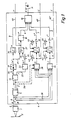
Fig. 1 zeigt ein Ausführungsbeispiel für eine Schaltungsanordnung zum Erkennen von Farbtönen und/oder Farben.1 shows an exemplary embodiment of a circuit arrangement for recognizing color tones and / or colors.
Ein optoelektronisches Abtastorgan 1 tastet eine beleuchtete farbige Fläche, beispielsweise eine Farbvorlage 2, ab, deren Farbtöne oder Farben erkannt werden sollen. Die Farbvorlage 2 kann eine Aufsichts- oder Durchsichtsvorlage sein. Das von der abgetasteten Farbvorlage 2 reflektierte oder durchgelassene Abtastlicht wird im Abtastorgan 1 mit Hilfe von Farbteilern, Korrekturfiltern und optoelektronischen Wandlern in die Farbmeßwert-Signale R, G und B umgewandelt, welche ein Maß für die Intensitäten der Grundfarbanteile "Rot", "Grün" und "Blau" an den abgetasteten Farben sind. Die Farbmeßwert-Signale R, G und B stellen die Raum- oder Farbkoordinaten der Farborte der abgetasteten Farben in dem kartesischen RGB-Farbraum dar. Das Abtastorgan 1, welches relativ zur Farbvorlage 2 verschiebbar ist, wird sowohl zum Ausmessen einzelner Farbpunkte in der Farbvorlage 2 als auch zum flächenmäßigen, punkt- und zeilenweisen Abtasten der Farbvorlage 2 während der eigentlichen Farb-oder Farbton-Erkennung verwendet. Ein Ausführungsbeispiel für ein Abtastorgan zeigt Fig. 8.An optoelectronic scanning element 1 scans an illuminated colored surface, for example a
Die Farbmeßwert-Signale R, G und B werden über Leitungen 3 einer dem Abtastorgan 1 nachgeschalteten Erkennungs-Schaltung 4 zugeführt und dort zunächst in einer Umformer-Stufe 5 logarithmiert oder teillogarithmiert und gegebenenfalls nach einer Gradationskurve korrigiert. Die logarithmierten Farbmeßwert-Signale R', G' und B' werden durch eine Matrizierung gemäß Gleichungen (1) in Chrominanz-Signale x und y und in ein Luminanz-Signal z umgeformt.![]()
![]()
Die Matrizierung entspricht einer Transformation der Farbkoordinaten des kartesischen RGB-Farbraumes in die Farbkoordinaten x, y und z des kartesischen Chrominanz/Luminanz-Farbraumes, wobei die Farbkoordinaten x und y die Lage der Farborte der Farben im XY-Farbkoordinatensystem der Chrominanzebene und die Farbkoordinate z die Helligkeitswerte der Farben kennzeichnenThe matrixing corresponds to a transformation of the color coordinates of the Cartesian RGB color space into the color coordinates x, y and z of the Cartesian chrominance / luminance color space indicate the brightness values of the colors
Die Erkennungs-Schaltung 4 erzeugt aus den zugeführten Signalen zunächst ein Farbton-Steuersignal T* auf einer Leitung 6, ein Farbsättigungs-Steuersignal S* auf einer Leitung 7, ein Luminanz-Steuersignal L* auf einer Leitung 8 und ein Hilfssteuersignal H auf einer Leitung 9.The
Farbton (T), Farbsättigung (S) und Luminanz (L) sind die zylindrischen Farbkoordinaten des Farbton/Farbsättigung/Luminanz-Farbraumes, wobei die Lage der Farborte in dessen Chrominanzebene durch die Farbtonwerte T als Winkel und durch die Farbsättigungswerte S als Radien festgelegt sind, während die Helligkeitswerte der Farben durch die Luminanz L bestimmt werden. Dabei besteht zwischen den Farbkoordinaten x, y und z des Chrominanz/Luminanz- Farbraumes und den Farbkoordinaten Farbton T, Farbsättigung S und Luminanz L des Farbton/Farbsättigung/ Luminanz-Farbraumes folgender Zusammenhang:
- T = c1 arc tan


- T = c 1 arc tan
In der Erkennungs-Schaltung 4 werden das Farbton-Steuersignal T*, das Farbsättigungs-Steuersignal S*, das Luminanz-Steuersignal L* sowie das Hilfssteuersignal H miteinander in einer Verknüpfungs-Stufe 10 zu einem Erkennungssignal E für Farbtöne oder Farben als Ausgangssignal der Erkennungs-Schaltung 4 auf einer Leitung 11 verknüpft.In the
Wenn eine Farbton-Erkennung durchgeführt werden soll, wird in der Erkennungs-Schaltung 4 ein sektorförmiger Farbton-Erkennungsbereich in der Chrominanzebene um einen in allen vier Quadranten frei wählbaren Farbton, nachfolgend als Schwerpunkt-Farbton To bezeichnet, abgegrenzt. In diesem Falle ist das Erkennungs- Signal E auf der Leitung 11 ein Farbton-Erkennungssignal E', das in der Verknüpfungs-Stufe 10 aus dem Farbton-Steuersignal T* und dem Hilfssteuersignal H gewonnen wird. Bei der punkt- und zeilenweisen Abtastung der Farbvorlage 2 während der eigentlichen Farbton-Erkennung liefert das Farbton-Erkennungssignal E' eine Aussage über den Abstand der Farbtöne der abgetasteten Farben von dem eingestellten Schwerpunkt-Farbton To, falls die Farbtöne der abgetasteten Farben innerhalb des abgegrenzten Farbton-Erkennungsbereiches liegen, anderenfalls ist das Farbton-Erkennungssignal E' gleich Null.If a color tone recognition is to be carried out, a sector-shaped color tone recognition area in the chrominance plane is delimited in the
Wenn eine Farb-Erkennung durchzuführen ist, wird der sektorförmige Farbton-Erkennungsbereich zusätzlich noch hinsichtlich der Helligkeit und der Farbsättigung abgegrenzt, so daß ein dreidimensionaler Farb-Erkennungsbereich um den Schwerpunkt-Farbton To entsteht. In diesem Falle ist das Erkennungs- Signal E ein Farb-Erkennungssignal E", welches durch eine zusätzliche Verknüpfung des Farbton-Steuersignals T* und des Hilfssteuersignals H bzw. des Farbton-Erkennungssignals E' mit dem Farbsättigungs-Steuersignal S* und/oder Luminanz-Steuersignal L* in der Verknüpfungs-Stufe 10 gebildet wird.If color recognition is to be carried out, the sector-shaped color recognition area is additionally delimited with regard to the brightness and the color saturation, so that a three-dimensional color recognition area arises around the focal color tone T o . In this case, the detection signal E is a color detection signal E ", which is obtained by additionally linking the hue control signal T * and the auxiliary control signal H or the hue detection signal E 'with the color saturation control signal S * and / or luminance Control signal L * is formed in the
Aufbau und Wirkungsweise der Erkennungs- Schaltung 4 sollen nachfolgend näher erläutert werden, und zwar zunächst am Beispiel einer Farbton-Erkennung.The structure and mode of operation of the
Zunächst wird der gewünschte Schwerpunkt-Farbton To, um den ein Farbton-Erkennungsbereich abgegrenzt werden soll, durch Vorgabe seiner Farbmeßwerte R0, G0 und B0 im RGB-Farbkoordinatensystem bzw. seiner durch Matrizierung gebildeten Chrominanzwerte xo und yo im XY-Farbkoordinatensystem oder durch Ausmessen eines Probenpunktes in der Farbvorlage 2 mit Hilfe des Abtastorgans 1 definiert.First, the desired focus hue T o by which a hue detection area is to be delimited is determined by specifying its color measurement values R 0 , G 0 and B 0 in the RGB color coordinate system or its chrominance values x o and y o formed by matrixing in XY -Color coordinate system or by measuring a sample point in the
Die Chrominanzwerte xo und yo werden erfindungsgemäß durch eine auf den ausgewählten Schwerpunkt-Farbton To einstellbare Matrizierung nach Gleichungen (3) in entsprechende Farbkoordinaten x'o und y'o transformiert, wobei die Transformations- Koeffizienten b, c, d und e so bestimmt werden, daß die Bedingungen x'0 > 0 und y'0 = 0 erfüllt sind.![]()
![]()
![]()
![]()
Im gewählten Ausführungsbeispiel werden vorzugsweise Transformations-Koeffizienten der Form b = e = cos a und c = -d = sin α verwendet, so daß die Matrizierung einer Drehung eines X'Y'-Farbkoordinatensystems um einen Winkel a gegenüber dem ursprünglichen XY-Farbkoordinatensystem nach Gleichungen (4) entspricht.![]()
![]()
![]()
![]()
Der zur Erfüllung der Bedingungen x'o > 0 und y'0 = 0 erforderliche Winkel α0 wird in einer Transformations-Stufe 13 durch einen automatischen Abgleichvorgang bei laufender Überprüfung der Bedingungen x'o > 0 und y'o = 0 in einer Überwachungs-Stufe innerhalb der Transformations-Stufe 13 bestimmt, indem der Winkel a verändert wird, bis die Überwachungs-Stufe die Erfüllung der Bedingungen festgestellt hat. Der gefundene Winkel α o = arc tan yo/xo entspricht dem Schwerpunkt-Farbton To, und die X'-Achse des um den Winkel α0 gedrehten X'Y'-Farbkoordinatensystems verläuft durch den transformierten Farbort F'0 des Schwerpunkt-Farbtones To. Die beschriebene Koordinaten- Drehung entspricht einer Drehung des Chrominanz/Luminanz-Farbraumes um die Z-Achse.The to satisfy the conditions x 'o> 0, and y' 0 = 0 required angle α 0 is in a
Der gefundene Winkel αo wird in der Transformations-Stufe 13 gespeichert und bei der eigentlichen Farbton-Erkennung zur laufenden Transformation der Chrominanz-Signale x und y in die gedrehten Chrominanz-Signale x' und y' gemäß Gleichungen (5) verwendet, wobei das gedrehte Chrominanz-Signal y' von Null verschieden ist für alle Farbtöne der abgetasteten Farben, die von dem ausgewählten Schwerpunkt-Farbton To abweichen, und gleich Null ist für alle Farbtöne, die mit dem ausgewählten Schwerpunkt-Farbton To übereinstimmen. Es liegt im-Rahmen der Erfindung, die Matrizierung nach Gleichungen (1) und (4) in einem einzelnen Schritt durchzuführen.![]()
![]()
![]()
![]()
Ein detailliertes Ausführungsbeispiel für die Transformations-Stufe 13 wird in Fig. 9 angegeben.A detailed exemplary embodiment for the
Die zuvor beschriebene Koordinaten-Drehung wird anhand einer grafischen Darstellung in Fig. 2 nochmals verdeutlicht.The previously described coordinate rotation is illustrated once again with the aid of a graphic representation in FIG. 2.
Fig. 2 zeigt die Chrominanzebene des Chrominanz/Luminanz-Farbraumes mit dem XY-Farbkoordinatensystem 14, wobei die Z-Achse (Grauachse) des Chrominanz/Luminanz-Farbraumes senkrecht zur Chrominanzebene verläuft. Ein transformierter Farbort F'o eines ausgewählten Schwerpunkt-Farbpunkts To ist im XY-Farbkoordinatensystem 14 durch die Farbkoordinaten xo und yo definiert. Gleichzeitig ist das um den Winkel ao gedrehte X'Y'-Farbkoordinatensystem 15 dargestellt, dessen X'-Achse durch den Farbort Fo verläuft, so daß der Farbort F'o im gedrehten X'Y'-Farbkoordinatensystem 15 die Farbkoordinaten x'p > 0 und y'o = 0 aufweist. Der Winkel ao = arc tan yo/xo entspricht dem Schwerpunkt-Farbton To im XY-Farbkoordinatensystem 14. Gleichzeitig ist symmetrisch zur X'-Achse des gedrehten X'Y'-Farbkoordinatensystems 15 ein sektorförmiger Farbton-Erkennungsbereich 16 dargestellt, dessen Grenzwinkel βg (Öffnungswinkel 2 βg) bezogen auf die X'-Achse zur Eingrenzung der zu erkennenden Farbtöne einstellbar ist. Für einen beliebigen Farbort F' innerhalb des Farbton-Erkennungsbereiches 16 entspricht in erster Näherung bei kleinem Winkel das gedrehte Chrominanz-Signal x' der Farbsättigung und der Quotient y'/x' = tan β der Abweichung des abgetasteten Farbtons von dem gewählten Schwerpunkt-Farbton To, wobei der Quotient mit wachsender Abweichung ansteigt.2 shows the chrominance plane of the chrominance / luminance color space with the XY color coordinate system 14, the Z axis (gray axis) of the chrominance / luminance color space running perpendicular to the chrominance plane. A transformed color locus F ' o of a selected focus color point T o is defined in the XY color coordinate system 14 by the color coordinates x o and y o . At the same time, the X'Y'-color coordinate
Außerdem zeigt Fig. 2 noch die zu den abgegrenzten Farbtönen gehörenden Komplementärfarbtöne innerhalb eines Sektors 17, der durch Spiegelung des Farbton-Erkennungsbereiches 16 an der Y'-Achse des X'Y'-Farbkoordinatensystems 15 entstanden ist. Das gedrehte Chrominanz-Signal x' ist für die abgegrenzten Farbtöne positiv, dagegen für die Komplementärfarbtöne negativ. Bei der Farbton bzw. Farberkennung erweist es sich oft als notwendig, um die Grauachse 18 einen zylindrischen oder tonnenförmigen Farberkennungsraum für "Grau" abzugrenzen, damit Farbschwankungen oder Verläufe im Grau als einheitliches Grau erkannt werden. Von einem solchen Farberkennungsraum für "Grau" ist in Fig. 2 noch die kreisförmige Schnittfläche 19 dargestellt, deren Radius durch einen Grenz-Farbsättigungswertx' definiert ist.FIG. 2 also shows the complementary color tones belonging to the delimited color tones within a
Zunächst zurück zu Fig. 1.First, back to Fig. 1.
Das in der Transformations-Stufe 13 erzeugte gedrehte Chrominanz-Signal x' wird über eine Leitung 20 einer Auswahl-Stufe 21 in Form einer Diodenschaltung zugeführt, welche nur die positiven Werte des gedrehten Chrominanz-Signals x' als Signal +x' durchläßt. Am Ausgang der Auswahl-Stufe 21 erscheint somit immer nur dann ein Signal, wenn der von der Farbvorlage 2 abgetastete Farbton, bezogen auf die Y'-Achse des gedrehten X'Y'-Farbkoordinatensystems 15 (Fig. 2), auf der Seite des abgegrenzten Farbton-Erkennungsbereiches 16 liegt, wenn es sich also um keinen Komplementärfarbton handelt, so daß in vorteilhafter Weise eine exakte Trennung von Farbtönen und Komplementärfarbtönen erreicht wird.The rotated chrominance signal x 'generated in the
Das gedrehte Chrominanz-Signal y' gelangt von der Transformations-Stufe 13 über eine Leitung 22 auf eine Betrags-Stufe 23. In der Betrags-Stufe 23 wird der Betrag des gedrehten Chrominanz-Signals y' als Signal /y'/ gebildet. Durch amplitudenmäßige Einstellung des Signals /y'/ mittels eines Potentiometers 24 wird der Grenzwinkel ßg für den gewünschten Farbton-Erkennungsbereich 16 (Fig. 2) festgelegt. Die Signale + x' und /y'/ werden über Leitungen 25 und 26 einer Dividier-Stufe 27 zugeführt, in der durch Quotientenbildung das Farbton-Signal T' gemäß Gleichunq (6) qewonnen wird.![]()
![]()
Das Farbton-Signal T' liefert eine eindeutige Aussage über die betragsmäßige Abweichung eines auf der Farbvorlage 2 abgetasteten Farbtones von dem eingestellten Schwerpunkt-Farbton To nach beiden Richtungen hin, wobei bei Farbton-Übereinstimmung β = 0 ist.The hue signal T 'provides unambiguous information about the amount of deviation of a hue scanned on the
Durch die erfindungsgemäße Koordinaten- Drehung zur Gewinnung des Farbton-Signals T' werden die üblichen Schwierigkeiten bei der Bildung eines farbtonkennzeichnenden Signals. die sich aufgrund der Doppeldeutigkeit der Tangensfunktion und der Unsymmetrie innerhalb eines Quadranten ergeben, in vorteilhafter Weise vermieden und somit eine exaktere Farbtontrennung erreicht. Das Farbton-Signal T' wird in einer der Dividier-Stufe 27 nachgeschalteten Signalformer-Stufe 30 in das Farbton-Steuersignal T* auf der Leitung 6 umgewandelt.The coordinate rotation according to the invention for obtaining the hue signal T 'eliminates the usual difficulties in the formation of a hue-indicating signal. which result from the ambiguity of the tangent function and the asymmetry within a quadrant, are advantageously avoided and thus achieve a more precise color separation. The hue signal T 'is converted into the hue control signal T * on line 6 in a signal shaper stage 30 downstream of the
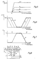
Fig. 3 zeigt verschiedene Verläufe des Farbton-Steuersignals T* in Abhängigkeit des Winkels β Die Verläufe 28 und 29 ergeben sich bei unterschiedlich eingestellten Grenzwinkeln βg für den Farbton-Erkennungsbereich 16, für den Fall, daß in der Signalformer-Stufe 30 keine Signalbeeinflussung stattfindet und das Farbton-Steuersignal T* dem Farbton-Signal T' entspricht Mit Hilfe der Signalformer-Stufe 30 kann das Farbton-Signal T' amplituden- und formmäßig noch verändert werden, so daß beispielsweise das Farbton-Steuersignal T* im Bereich kleiner Winkel β nach Verlauf 31 verflacht wird.Fig. 3 shows different courses of the hue control signal T * as a function of the angle β. The
Aus dem Farbton-Steuersignal T* auf der Leitung 6 und dem Hilfssteuersignal H auf der Leitung 9 wird in der Verknüpfungs-Stufe 10. die im Ausführungsbeispiel als Subtrahier-Stufe ausgebildet ist, das Farbton-Erkennungssignal E' auf der Leitung 11 gemäß Gleichung (7) gewonnen, wobei sich die beiden Schalter 32 und 33 in der dargestellten geöffneten Position befinden.![]()
![]()
Alternativ kann die Verknüpfung von Hilfssteuersignal H und Farbton-Steuersignal T* auch multiplikativ erfolgen.Alternatively, the auxiliary control signal H and the hue control signal T * can also be combined multiplicatively.
Das Hilfssteuersignal H, das in einem Signalgenerator 34 erzeugt wird, hat beispielsweise einen konstanten Wert Ho, der dann vorzugsweise Ho = tan yo/xo gewählt wird. Vorteilhafter ist es aber, das Hilfssteuersignal H, wie im beschriebenen Ausführungsbeispiel, in erster Näherung von der Farbsättigung, d. h vom Signal +x', abhängig zu machen. In diesem Fall hat das Hilfssteuersignal H = f (x') vom maximalen Farbsättigungswert bis in die Nähe des bereits in Fig. 2 erläuterten Grenz-Farbsättigungswertes x'g den konstanten Wert Ho, fällt dann ab und hat zwischen dem Grenz-Farbsättigungswert x'g und der Grauachse (x' = 0) den Wert Null. Fig. 10 zeigt ein Ausführungsbeispiel für den Signalgenerator 34.The auxiliary control signal H, which is generated in a
In Fig. 4 sind verschiedene Verläufe des Farbton-Erkennungssignals E' in Abhängigkeit des Winkels β für verschiedene Grenzwinkel βg der Farbton-Erkennungsbereiche 16 und für ein konstantes Hilfssteuersignal Ho bzw. für den zwischen dem Grenz-Farbsättigungswert und dem maximalen Farbsättigungswert liegenden Bereich des Hilfssteuersignals H = f (x') dargestellt.In FIG. 4 different gradients are of the hue recognition signal E 'as a function of the angle β for different cut-off angle β g of the
Das Farbton-Erkennungssignal E' hat für Farbtöne, die dem ausgewählten Schwerpunkt-Farbton To entsprechen (ß = 0), einen maximalen Wert Em = H0, der bei H0 = tan y0/x0 genau dem Schwerpunkt-Farbton To entspricht.The hue detection signal E 'has a maximum value E m = H 0 for hues that correspond to the selected focal point hue T o (ß = 0), which is exactly the focal point hue at H 0 = tan y 0 / x 0 T o corresponds.
Mit steigender Abweichung der abgetasteten Farbtöne von dem Schwerpunkt-Farbton To fällt das Farbton-Erkennungssignal E' ab und erreicht bei dem jeweiligen Grenzwinkel βα der eingestellten Farbton-Erkennungsbereiche den Wert E' = 0.With increasing deviation of the sampled color tones from the focus color tone T o , the color tone detection signal E 'drops and reaches the value E' = 0 at the respective critical angle β α of the set color tone detection areas.
Alternativ zur Einstellung des Grenzwinkels βg des Farbton-Erkennungsbereiches mit Hilfe des Potentiometers 24 kann der Grenzwinkel βg auch durch Amplitudenänderung des Farbton-Signals T' in der Signalformer-Stufe 30 oder des Wertes Ho des Hilfssteuersignals H im Signalgenerator 34 eingestellt werden.As an alternative to setting the limit angle β g of the hue detection range using the
Fig. 5 zeigt verschiedene Verläufe des Farbton-Erkennungssignals E' in Abhängigkeit des Signals x' bzw. der Farbsättigung für den Fall, daß das Hilfssteuersignal H = f (x') und der Winkel β Parameter sind. Durch die Abhängigkeit des Farbton-Erkennungssignals E' von der Farbsättigung wird in vorteilhafter Weise eine Abgrenzung nach "Grau" erreicht.Fig. 5 shows different courses of the hue detection signal E 'depending on the signal x' or the color saturation in the event that the auxiliary control signal H = f (x ') and the angle β are parameters. Due to the dependence of the color tone detection signal E 'on the color saturation, a delimitation according to "gray" is advantageously achieved.
Eine Abhängigkeit des Farbton-Erkennungssignals E' von der Farbsättigung kann alternativ auch dadurch erreicht werden, daß das Farbton-Steuersignal T* in der Verknüpfungs-Stufe 10 mit dem Signal +x' multiplikativ verknüpft wird.A dependency of the hue detection signal E 'on the color saturation can alternatively be achieved by multiplying the hue control signal T * in the
Wenn eine Farb-Erkennung durchgeführt wird, muß ein dreidimensionaler Farb-Erkennungsbereich im Farbton/ Farbsättigung/ Luminanz-Farbraum abgegrenzt werden, indem der sektorförmige Farbton-Erkennungsbereich zusätzlich hinsichtlich der Helligkeit und/oder der Farbsättigung eingegrenzt wird.When color detection is performed, a three-dimensional color detection area in the hue / saturation / luminance color space must be delimited by additionally narrowing the sector-shaped hue detection area in terms of brightness and / or color saturation.
Zur Eingrenzung bezüglich der Helligkeit wird in der Erkennungs-Schaltung 4 in einem Luminanz-Signalgenerator 35, dem die Farbmeßwert-Signale R, G und B über die Leitungen 36 zugeführt werden, aus mindestens einem, vorzugsweise aus allen drei Farbmeßwert-Signalen R, G und B gemäß der Beziehung L' = f, R + f2G + f3B ein Luminanz-Signal L' gewonnen. Als Luminanz-Signal L' kann auch das in der Umformer-Stufe 5 gebildete Luminanz-Signal z verwendet werden, falls an der Bildung des Luminanz-Signals L' alle drei Farbmeßwert-Signale R, G und B beteiligt sind. In diesem Fall kann der Luminanz-Signalgenerator 35 entfallen.To limit the brightness, in the
Zur Eingrenzung bezüglich der Farbsättigung erzeugt ein Farbsättigungs-Signalgenerator 38 ein Farbsättigungs-Signal S'. Ein Ausführungsbeispiel für den Farbsättigungs-Signalgenerator 38 zeigt Fig. 11. Das Farbsättigungs-Signal S' kann gemäß der Gleichung S' = √x2 + y2 aus den in der Umformer-Stufe 5 gebildeten Chrominanz-Signalen x und y gewonnen werden, welche dem Farbsättigungs-Signalgenerator 38 über die gestrichelt dargestellten Leitungen 39 zugeführt werden. In diesem Fall gibt das Farbsättigungs-Signal S' die exakten Farbsättigungswerte wieder. Der Farbsättigungs-Signalgenerator 38 enthält dann entsprechende Rechenbausteine (Quadrierer, Addierer, Radizierer), die aber keine hohe Arbeitsgeschwindigkeit zulassen. Um diese Schwierigkeit zu umgehen, wird in vorteilhafter Weise ein an die exakten Farbsättigungswerte angenähertes Farbsättigungs-Signal S' verwendet. In diesem Falle wird das angenäherte Farbsättigungs-Signal S' aus den über die Leitungen 36 an den Farbsättigungs-Signalgenerator 38 gelangenden Farbmeßwert-Signalen R, G und B abgeleitet, indem im Farbsättigungs-Signalgenerator 38 laufend das maximale und das minimale Farbmeßwert-Signal festgestellt und die Differenz der Extremwerte gebildet wird, welche näherungsweise dem Farbsättigungs-Signal S' entspricht, da das maximale Farbmeßwert-Signal einer, abgetasteten Farbe jeweils die Farbsättigung und das minimale Farbmeßwert-Signal den Grauton dieser Farbe repräsentiert. Da der Farbsättigungs-Signalgenerator 38 nunmehr nicht die oben genannten Rechenbausteine enthält, kann durch die angegebene Signalbildung in vorteilhafter Weise die Arbeitsgeschwindigkeit der Schaltungsanordnung und damit auch die Abtastgeschwindigkeit für die zu analysierende Farbvorlage 2 erhöhtwerden. Falls eine gröbere Näherung bei der Bildung des Farbsättigungs-Signals S' erlaubt ist, kann anstelle des Farbsättigungs-Signals S' auch das Signal x' verwendet werden.To limit the color saturation, a color
Das Farbton-Signal T', das Farbsättigungs-Signal S' sowie das Luminanz-Signal L' sind über Leitungen 40, 40' und 40" an den Ausgang der Erkennungs-Schaltung 4 für einen später beschriebenen Anwendungsfall der Erkennungs- Schaltung 4 geführt.The hue signal T ', the color saturation signal S' and the luminance signal L 'are conducted via
Dem Luminanz-Signalgenerator 35 ist eine Begrenzer-Stufe 41 nachgeschaltet, in der aus dem Luminanz-Signal L' das Luminanz-Steuersignal L* erzeugt wird. Ebenso ist dem Farbsättigungs-Signalgenerator 38 eine entsprechende Begrenzer-Stufe 42 nachgeschaltet, welche das Farbsättigungs-Signal S' in das Farbsättigungs-Steuersignal S* umwandelt. Die Bildung des Luminanz-Steuersignals L* und des Farbsättigungs-Steuersignal S* erfolgt durch Begrenzung des Luminanz-Signals L' und des Farbsättigungs-Signals S' mit Hilfe von Kompensationsspannungen, welche an Potentiometern 43 und 44 bzw. 45 und 46 einstellbar sind. Gleichzeitig können das Luminanz-Signal L' und das Farbsättigungs-Signal S' in den Begrenzer-Stufen 41 und 42 noch amplitudenmäßig und/oder nach Gradationskurven nichtlinear verändert werden. Ein Ausführungsbeispiel für die identisch aufgebauten Begrenzer-Stufen 41 und 42 zeigt Fig. 12.The
Das Luminanz-Steuersignal L* auf der Leitung 8 und/oder das Farbsüttigungs-Steuersignal S* auf der Leitung 7 werden über die Schalter 32 und 33 auf die Verknüpfungs-Stufe 10 gegeben, in der gemäß Gleichung (8) das Farb-Erkennungssignal E" auf der Leitung 11 erzeugt wird.![]()
![]()
![]()
![]()
Alternativ kann die Verknüpfung von Farbton-Erkennungssignal E' mit dem Luminanz-Steuersignal L* und/oder dem Farbsättigungs-Steuersignal S* auch multiplikativ erfolgen.As an alternative, the combination of hue detection signal E 'with the luminance control signal L * and / or the color saturation control signal S * can also be carried out multiplicatively.
Mit Hilfe der Potentiometer 43 bis 46 an den Begrenzer-Stufen 41 und 42 können bei der Abgrenzung der Farb-Erkennungsbereiche die Helligkeitswerte und Farbsättigungswerte festgelegt werden, bei denen die Helligkeit und die Farbsättigung der abgetasteten Farben Einfluß auf den Verlauf des Farb-Erkennungssignals E" nehmen.With the help of the
Mit Hilfe der Schalter 32 und 33 kann außerdem eine Auswahl der Signale getroffen werden, die an der Bildung des Farb-Erkennungssignals E" beteiligt werden sollen.The
Der Verlauf des Farb-Erkennungssignals E" in bezug auf den Farbton der abgetasteten Farben entspricht dem in Fig. 4 dargestellten Verlauf des Farbton-Erkennungssignals E', wenn Helligkeit und Farbsättigung unberücksichtigt bleiben.The course of the color detection signal E ″ with respect to the hue of the sampled colors corresponds to the course of the color tone detection signal E ′ shown in FIG. 4 if brightness and color saturation are not taken into account.
Fig. 6 zeigt verschiedene, durch die Potentiometer 43 bis 46 an den Begrenzer-Stufen 41 und 42 einstellbare Verläufe des Luminanz-Steuersignal L* in Abhängigkeit der Helligkeit bzw des Farbsättigungs-Steuersignals S* in Abhängigkeit der Farbsättigung.FIG. 6 shows various courses of the luminance control signal L * depending on the brightness or the color saturation control signal S * depending on the color saturation, which can be adjusted by the
In Fig. 7 sind die zugehörigen Verläufe des Farb-Erkennungssignals E" in Abhängigkeit der Helligkeit bzw. der Farbsättigung darstellt. Zur Vereinfachung der Darstellung ist angenommen, daß der abgetastete Farbton gerade dem ausgewählten Schwerpunkt-Farbton To entspricht.7 shows the associated courses of the color detection signal E "as a function of the brightness or the color saturation. To simplify the illustration, it is assumed that the sampled color tone corresponds exactly to the selected focus color tone T o .
Sollen im wesentlichen dunkle Farben erkannt werden, wird mit Hilfe eines der Potentiometer an der Begrenzer-Stufe 41 z. B. der Verlauf 47 des Luminanz-Steuersignals L* eingestellt, wodurch sich der Verlauf 47' des Farb-Erkennungssignals E" ergibt. In diesem Falle hat das Farb-Erkennungssignal E" bei dunklen Farben einen hohen Signalpegel, und die Signalbegrenzung setzt erst bei helleren Farben ein.If essentially dark colors are to be recognized, z. B. the
Sollen dagegen im wesentlichen helle Farben erkannt werden, wird mit Hilfe des anderen Potentiometers an der Begrenzer-Stufe 41 beispielsweise der Verlauf 48 eingestellt, und es ergibt sich der Verlauf 48" des Farb-Erkennungssignals E". In diesem Falle hat das Farb-Erkennungssignal E" bei hellen Farben einen hohen Signalpegel, der zu dunklen Farben hin begrenzt wird. Auf diese Weise können in vorteilhafter Weise helle und dunkle Farben exakt voneinander getrennt werden. Zur Abgrenzung eines Helligkeits-Bereiches kann mit Hilfe beider Potentiometer an der Begrenzer-Stufe 41 auch der Verlauf 49 des Luminanz-Steuersignals L* erzeugt werden In diesem Falle hat das Farb-Erkennungssignal E" den Verlauf 49', wodurch eine Begrenzung zu hellen und dunklen Farben um Farben mittlerer Helligkeit erreicht wird. So lassen sich im wesentlichen Farben erkennen, die in oder in der Nähe der Chrominanzebene liegen.If, on the other hand, essentially bright colors are to be recognized, the
Durch eine sinngemäße Einstellung der Potentiometer an der Begrenzer-Stufe 42 kann eine Abgrenzung der abgetasteten Farben hinsichtlich kleiner oder großer Farbsättigungswerte sowie hinsichtlich eines Farbsättigungs-Bereiches vorgenommen werdenBy appropriately adjusting the potentiometers at the
Fig. 8 zeigt ein Ausführungsbeispiel für das optoelektronische Abtastorgan 1. Das von der Farbvorlage 2 reflektierte oder durchgelassene Abtastlicht 50 gelangt durch Objektive 51 und 52 und durch eine Blende 53 in das Abtastorgan 1 und wird dort mittels zweier dichroitischer Farbteiler 54 und 55 in drei Teilbündel 56, 57 und 58 aufgespalten. Die Teilbündel 56, 57 und 58 fallen durch Korrektur-Farbfilter 59, 60 und 61 auf drei optoelektronische Wandler 62, 63 und 64, die das empfangene Teillicht entsprechend den Intensitäten der Grundfarben-Anteile an den abgetasteten Farben in die primären Farbmeßwert-Signale R, G und B umwandeln8 shows an exemplary embodiment of the optoelectronic scanning element 1. The
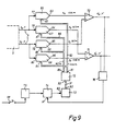
Fig. 9 zeigt ein Ausführungsbeispiel für die Transformations-Stufe 13.9 shows an exemplary embodiment for the
In der Transformations-Stufe 13 werden die Chrominanz-Signale x0 und y0 des ausgewählten Schwerpunkt-Farbtons To während eines Abgleichvorganges durch monotone Änderung des Winkels α gedreht, bis die gedrehten Chrominanz-Signale x'o > 0 und y'o = 0 sind. wobei der dabei gefundene Winkel a o festgehalten wird. Diese Koordinaten-Drehung läuft gemäß Gleichung (4) ab.In the
Während der punkt- und zeilenweisen Abtastung der zu analysierenden Farbvorlage werden dann die laufend erzeugten Chrominanz- . Signale x und y gemäß Gleichung (5) gedreht.During the point-by-line and line-by-line scanning of the color template to be analyzed, the continuously generated chrominance. Signals x and y rotated according to equation (5).
Die Transformations-Stufe 13 besteht aus vier Multiplizier-Stufen 66, 67, 68 und 69, einer Addier-Stufe 70, einer Subtrahier-Stufe 71, einem Festwert-Speicher 72, einem Adreßzähler 73, einer Tor-Stufe 74, einem Taktgenerator 75 sowie aus einer Überwachungs-Stufe 76.The
Die Multiplizier-Stufe 66, 67, 68 und 69 sind in vorteilhafter Weise aus multiplizierenden D/A-Wandlern, z. B. aus integrierten Bausteinen vom Typ AD 7542 der Fa. Analog Devices, aufgebaut. In einen solchen multiplizierenden D/A-Wandler kann ein wählbarer Faktor in Form von Digitalwerten über einen Dateneingang eingegeben werden, die in einem internen Register speicherbar sind. Ein am Eingang des multiplizierenden D/A-Wandiers anstehendes analoges Signal wird mit dem eingestellten Faktor multipliziert, wobei das Produkt wiederum als analoges Signal am Ausgang des multiplizierenden D/A-Wandlers zur Verfügung steht.The
Während des Abgleichvorganges wird das von der gestrichelt angedeuteten Umformer-Stufe 5 kommenden Chrominanz-Signal xo auf die Eingänge 77 und 78 der Multiplizier-Stufen 66 und 67 gegeben, während das Chrominanz-Signal yo auf die Eingänge 79 und 80 der Multiplizier-Stufen 68 und 69 gelangt.During the adjustment process, the chrominance signal x o coming from the
Im Festwert-Speicher 72 sind für Winkelwerte a von 0 bis 360; die entsprechenden Sinus- und Cosinus-Werte als Digitalwerte b = e = cos a und c = d = sin a durch die zugehörigen Winkelwerte a als Adressen des Festwert-Speichers 72 abrufbar gespeichert. Der Datenausgang 81 des Festwert-Speichers 72 für die Digitalwerte b = e = cos a ist über einen Daten-Bus 82 mit den Dateneingängen 83 und 84 der Multiplizier-Stufen 66 und 69 und der entsprechende Datenausgang 85 für die Digitalwerte c = d = sin α über einen Daten-Bus 86 mit den Dateneingängen 87 und 88 der Multiplizier-Stufen 67 und 68 verbunden.In the fixed
Der einschaltbare Taktgenerator 75 steht über die Tor-Stufe 74 mit dem Takteingang 89 des Adreßzählers 73 in Verbindung. Der Ausgang 90 des Adreßzählers 73 ist über einen Adreß-Bus 91 an den Adreßeingang 92 des Festwert-Speichers 72 angeschlossen. Die Ausgänge 93 und 95 der Multiplizier-Stufen 66 und 68 stehen mit der Addier-Stufe 70 und die Ausgänge. 94 und 96 der Multiplizier-Stufen 67 und 69 mit der Subtrahier-Stufe 71 in Verbindung. Der Ausgang der Addier-Stufe 70 und der Ausgang der Subtrahier-Stufe 71 sind an die Überwachungs-Stufe 76 für die Bedingungen x'o > 0 und y'o = 0 angeschlossen. Die Überwachungs-Stufe 76 steht mit einem Steuereingang 97 der Tor-Stufe 74 in Verbindung.The
Der Abgleichvorgang wird durch Einschalten des Taktgenerators 75 mit Hilfe einer Taste 98 eingeleitet. Der Zähltakt des Taktgenerators 75 wird in den Adreßzähler 73, der vorher rückgesetzt wurde, eingezählt, wobei der ansteigende Zählerstand monoton ansteigenden Winkelwerten a entspricht. Der Adreßzähler 73 ruft nacheinander die Adressen des Festwert-Speichers 72 auf, die zu den Winkelwerten α gehörenden Digitalwerte cos a und sin α werden in die Multiplizier-Stufen 66, 67, 68 und 69 übertragen und dort mit den entsprechenden Chrominanz-Signalen xo und yo multipliziert. Die Einzelprodukte werden gemäß Gleichung (4) addiert bzw. voneinander subtrahiert, so daß an dem Ausgang der Addier-Stufe 70 das gedrehte Chrominanz-Signal x'o und am Ausgang des Subtrahier-Stufe 71 das gedrehte Chrominanz-Signal y'o erscheint. Dabei werden die gedrehten Chrominanz-Signale x'o und y'o laufend von der Überwachungs-Stufe 76 überprüft. Die Überwachungs-Stufe 76 gibt ein Steuersignal an die Tor-Stufe 74 ab, wenn die Bedingungen erfüllt sind, wodurch der Zähltakt unterbrochen wird. Der dabei erreichte und fixierte Zählerstand im Adreßzähler 73 entspricht dem gesuchten Winkel ao.The adjustment process is initiated by switching on the
Fig. 10 a zeigt ein Ausführungsbeispiel für den Signalgenerator 34 zur Erzeugung des Hilfssteuersignals H in Abhängigkeit des Signals x'.10 a shows an exemplary embodiment of the
Der Signalgenerator 34 besteht aus einem invertierenden Verstärker 100, dessen Ausgang über eine Diode 101 und über ein Netzwerk 102 mit dem invertierenden Eingang des Verstärkers 100 verbunden ist. Der invertierende Eingang des Verstärkers 100 ist außerdem über einen ersten Summier-Widerstand 103 mit dem Signal x' beaufschlagt und über einen zweiten Summier-Widerstand 104 an ein Potentiometer 105 angeschlossen. An dem Potentiometer 105 kann eine Kompensationsspannung Uk1 eingestellt werden, die dem gewünschten Grenz-Farbsättigungswert x'9 entspricht. Der nichtinvertierende Eingang des Verstärkers 100 ist über einen Widerstand 106 und die Anode der Diode 101 über einen Widerstand 107 an Massepotential gelegt. Bei Werten des Signals x'. die betragsmäßig kleiner als die Kompensationsspannung Uk1 sind, ist das Hilfssteuersignal H = 0. Erreicht das Signal x' betragsmäßig die Kompensationsspannung Uk1, steigt das Hilfssteuersignal H entsprechend der im Netzwerk 102 eingestellten Verstärkung an und erreicht dann einen ebenfalls durch das Netzwerk 102 vorgegebenen Grenzwert Ho The
Fig. 10 b zeigt den Verlauf des Hilfssteuersignals H am Ausgang des Signalgenerators 34.10 b shows the profile of the auxiliary control signal H at the output of the
Fig. 11 zeigt ein Ausführungsbeispiel für den Farbsättigungs-Signalgenerator 38 zur Erzeugung des Farbsättigungs-Signals S' aus den Farbmeßwert-Signalen R, G und B.11 shows an exemplary embodiment of the color
Die vom nicht dargestellten Abtastorgan 1 gelieferten Farbmeßwert-Signale R, G und B werden in einer Logarithmier-Stufe 109 logarithmiert oder teillogarithmiert und gleichzeitig einer Maximumauswahl-Stufe 110 und einer Minimumauswahl-Stufe 111 zugeführt, welche aus den Farbmeßwert-Signalen R, G und B jeweils das maximale bzw. minimale Farbmeßwert-Signal feststellen. In einer der Maximumauswahl-Stufe 110 und der Minimumauswahl-Stufe 111 nachgeschalteten Subtrahier-Stufe 112 wird das Farbsättigungs-Signal S' als Differenzsignal aus den festgestellten maximalen und minimalen Farbmeßwert-Signalen gebildet, welches näherungsweise der Farbsättigung entspricht.The color measurement value signals R, G and B supplied by the scanning element 1, not shown, are in a
Fig. 12 zeigt ein Ausführungsbeispiel für die Begrenzer-Stufe 41 bzw. 42.12 shows an exemplary embodiment for the
Die Begrenzer-Stufe besteht aus drei identisch aufgebauten, invertierenden Verstärkern 113, 113' und 113". Die Ausgänge der Verstärker sind jeweils über Dioden 114, 114' und 114" und über Widerstände 115, 115' und 115" mit den invertierenden Eingängen der Verstärker 113, 113' und 113" verbunden. Die invertierenden Eingänge der Verstärker 113 und 113' sind gemeinsan über Summier-Widerstände 116 und 116' mit dem Farbsättigungs-Signal S' bzw. dem Luminanz-Signal L' beaufschlagt. Der inventierende Eingang des Verstärkers 113 ist über einen Summier-Widerstand 117 mit den Potentiometern 43 bzw. 45 und der invertierende Eingang des Verstärkers 113' über einen weiteren Summier-Widerstand 117' mit den Potentiometern 44 bzw. 46 verbunden. Der invertierende Eingang des Verstärkers 113" ist über einen Summier-Widerstand 116" an den Ausgang des Verstärkers 113 und über einen weiteren Summier-Widerstand 117' an eine positive Spannungsquelle 118 angeschlossen. Die Ausgänge der Verstärker 113' und 113" stehen über Summier-Widerstände 119 und 119' mit dem invertierenden Eingang eines Begrenzer-Verstärkers 120 in Verbindung, dessen Ausgang über eine Parallelschaltung eines Widerstandes 121 mit einer Begrenzer-Diode 122 auf den invertierenden Eingang gekoppelt ist. Am Ausgang des Begrenzer-Verstärkers 120 steht das Farbsättigungs-Steuersignal S* bzw. das Luminanz-Steuersignal L* mit den in den Fig. 6 dargestellten Verläufen zur Verfügung. Mit den Potentiometern 43 bzw. 45 und 44 bzw. 46 werden Kompensationsspannungen Uk2 und Uk3 eingestellt, welche die Einsatzpunkte der Spannungsbegrenzung bestimmen.The limiter stage consists of three identically constructed inverting
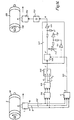
Fig. 13 zeigt ein Anwendungsbeispiel der Schaltungsanordnung zum Erkennen von Farbtönen oder Farben bei der Selektiv-Farbkorrektur in einem Farbscanner, mit dem Farbauszüge für den Mehrfarben-Mischdruck (Papierdruck) hergestellt werden.13 shows an application example of the circuit arrangement for recognizing color tones or colors in the selective color correction in a color scanner, with which color separations for multicolor mixed printing (paper printing) are produced.
Die Farbvorlage 2, von der Farbauszüge hergestellt werden sollen, ist auf eine rotierende Abtasttrommel 123 eines nicht näher dargestellten Farbscanners aufgespannt und wird von dem optoelektronischen Abtastorgan 1, welches sich axial an der Abtasttrommel 123 entlangbewegt, punkt- und zeilenweise, trichromatisch abgetastet. Die durch die Vorlagenabtastung gewonnenen Farbmeßwert-Signale R, G und B gelangen über Leitungen 124 und eine Logarithmier-Stufe 125 auf eine erste Farbkorrektur-Schaltung 126 zur Grund-Farbkorrektur, in der die Farbmeßwert-Signale R, G und B nach den Gesetzmäßigkeiten der subtraktiven Farbmischung in die Farbauszugs-Signale Y, M und C zur Aufzeichnung der Farbauszüge "Gelb", "Magenta" und "Cyan" und gegebenenfalls noch in das Farbauszugs-Signal K für die Aufzeichnung des Farbauszugs "Schwarz" umgesetzt werden.The
Die Farbmeßwert-Signale R, G und B werden gleichzeitig über Leitungen 127 der nach Fig. 1 aufgebauten Erkennungs-Schaltung 4 zugeführt, an deren Ausgängen das Erkennungs-Signal E (Farbton-Erkennungssignal E' bzw. Farb-Erkennungssignal E") sowie das Farbton-Signal T', das Farbsättigungs-Signal S' und das Luminanz-Signal L' zur Verfügung stehen. Die Ausgangssignale der Erkennungs-Schaltung 4 werden an eine zweite Farbkorrektur-Schaltung 128 zur Selektiv-Farbkorrektur weitergegebenThe color measurement signals R, G and B are simultaneously fed via
Die zweite Farbkorrektur-Schaltung 128 weist eine Misch-Stufe 129 auf, die über eine Leitung 130 mit dem Erkennungssignal E sowie über Leitungen 131 und Schalter 132 mit dem Farbton-Signal T', dem Farbsättigungs-Signal S' und dem Luminanz-Signal L' beaufschlagt ist. In der Misch-Stufe 129, die z. B. als Multiplizierer ausgebildet ist, wird ein positives Signal + Um gebildet, von dem in einem Inverter 133 ein negatives Signal -Um abgeleitet wird. Zwischen dem positiven Signal +Um und dem negativen Signal-Um sind drei Potentiometer 134 geschaltet an denen drei selektive Farbkorrektur-Signale beider Polaritäten + YK, ± MK und CK für die Farbauszugs-Signale Y, M und C abgegriffen werden können, wobei die Potentiometerstellung sowohl die Korrekturstärke als auch die Korrekturrichtung bestimmt.The second
Die selektiven Farbkorrektur-Signale YK, MK und CK werden über Leitungen 135 an eine Überlagerungs-Stufe 136 im Signalweg der Farbauszugs-Signale Y, M und C gegeben, in der die selektiven Farbkorrektur-Signale YK, MK und CK den grundkorrigierten Farbauszugs-Signalen Y, M und C additiv überlagert werden. Die auf diese Weise korrigierten Farbauszugs-Signale Y'. M' und C' werden über Endverstärker 137 an Aufzeichnungsorgane 138 in Form von Schreiblampen gegeben. Auf einer ebenfalls rotierenden Aufzeichnungstrommel 139 sind Aufzeichnungsmedien 140 z. B. Filme aufgespannt. Die Aufzeichnungsorgane 138, deren Helligkeiten durch die jeweils zugeordneten Farbauszugs-Signale Y', M' oder C' moduliert sind, bewegen sich gemeinsam axial an der Aufzeichnungstrommel 139 entlang und nehmen gleichzeitig die punkt- und zeilenweise Belichtung der Filme vor. Die belichteten und entwickelten Filme sind die gewünschten Farbauszüge für den Mehrfarben-Mischdruck.The selective color correction signals Y K , M K and C K are fed via
In der Erkennungs-Schaltung 4 wird, wie ausführlich in Fig. 1 beschrieben, derjenige Farbton oder diejenige Farbe der Farbvorlage durch Abgrenzung eines entsprechenden Erkennungsbereiches festgelegt, die einer zusätzlichen, selektiven Farbkorrektur unterzogen werden sollen.In the
Im einfachsten Fall entspricht das in der Misch-Stufe 129 gebildete Signal +Um dem Erkennungssignale E. In vorteilhafter Weise wird das Signal + Um aber zusätzlich aus mindestens einem der in der Erkennungs-Schaltung 4 gewonnenen Signale oder Anteilen davon ermischt, die mittels der Schalter 132 auswählbar sind. Beispielsweise wird das Signal +Um durch Multiplikation des Erkennungssignals E mit dem Farbsättigungs-Signal S' gebildet und ist somit proportional der Farbsättigung.In the simplest case, the signal + Um formed in the
Die selektiven Farbkorrektur-Signale YK, MK und CK erreichen ihre maximalen Werte, wenn der in der Farbvorlage 2 abgetastete Farbton dem für die Selektiv-Farbkorrektur ausgewählten Schwerpunkt-Farbton To entspricht, nehmen mit wachsendem Abstand der abgetasteten Farbtöne zum Schwerpunkt-Farbton To ab und erreichen den Wert Null, wenn die abgetasteten Farbtöne am Rande des abgegrenzten Erkennungsbereiches liegen. Man erhält also verlaufende selektive Farbkorrektur-Signale, die sich in vorteilhafter Weise dem jeweiligen Farbverlauf anpassen.The selective color correction signals Y K , M K and C K reach their maximum values when the color tone sampled in the
Fig. 14 zeigt ein weiteres Anwendungsbeispiel der Schaltungsanordnung zum Erkennen von Farbtönen oder Farben nach Fig. 1 bei einem Farbscanner zur Herstellung von Farbauszügen für den Einzelfarbendruck.FIG. 14 shows a further application example of the circuit arrangement for recognizing color tones or colors according to FIG. 1 in a color scanner for producing color separations for single-color printing.
Wie bereits in der Beschreibungseinleitung dargelegt, wird beim Einzelfarbendruck abweichend vom Mehrfarben-Mischdruck jede zu druckende Einzelfarbe vor dem Druckprozeß ermischt und die verschiedenen Einzelfarben in getrennten Vorgängen auf das Druckmedium übertragen. Beim Einzelfarbendruck muß daher für jeden auszuziehenden Farbton bzw. für jede auszuziehende Einzelfarbe der Farbvorlage ein entsprechender Farbauszug hergestellt werden, wobei es darauf ankommt, daß der Farbverlauf der Farbvorlage im Farbauszug möglichst gut wiedergegeben wird.As already explained in the introduction to the description, in the case of single-color printing, in contrast to multi-color mixed printing, each individual color to be printed is mixed before the printing process and the various individual colors are transferred to the printing medium in separate processes. In the case of single-color printing, a corresponding color separation must therefore be produced for each color tone or for each individual color of the color original to be extracted, it being important that the color gradient of the color original is reproduced as well as possible in the color separation.
Die Farbvorlage 2, von der die entsprechenden Farbauszüge für den Einzelfarbendruck hergestellt werden sollen, befindet sich auf einer rotierenden Abtasttrommel 141 eines nicht näher dargestellten Farbscanners und wird von dem optoelektronischen Abtastorgan 1 wiederum punkt- und zeilenweise, trichromatisch abgetastet. Die bei der Vorlagenabtastung gewonnenen Farbmeßwert-Signale R, G und B gelangen über Leitungen 142 an die Erkennungs- Schaltung 4 gemäß Fig. 1. Die Erkennungs- Schaltung 4 möge jeweils auf denjenigen Farbton oder diejenige Farbe der Farbvorlage 2, nachfolgend mit Auszugsfarbton bzw. Auszugsfarbe bezeichnet, voreingestellt sein, von dem oder von der momentan ein Farbauszug aufgezeichnet werden soll. Die Erkennungs- Schaltung 4 gibt dann ein entsprechendes Erkennungssignal E auf einer Leitung 143 ab.The
Die im optoelektronischen Abtastorgan 1 gewonnenen Farbmeßwert-Signale R, G und B werden gleichzeitig über die Leitungen 142 auf eine Logarithmier-Stufe 144 gegeben, in der sie logarithmiert oder teillogarithmiert werden. Der Logarithmier-Stufe 144 ist eine Korrektur-Schaltung 145 zur Farb- und/oder Tonwertkorrektur nachgeschaltet. Diese Korrektur-Schaltung 145 kann z. B. ein Farbrechner für den Mehrfarben-Mischdruck sein. Die Korrektur-Schaltung 145 erzeugt Farbsignale F" F2 und F3, die je nach Einstellung der Korrekturregler in der Korrektur-Schaltung 145 den Farbauszugs-Signalen Y, M und C, Zwischenwerten oder aber auch den eingegebenen, unkorrigierten Farbmeßwert-Signalen R, G und B entsprechen können. Die Farbsignale F" F2 und F3 werden einem Auswahl-Schalter 146 zugeführt, mit dem dasjenige Farbsignal F für die Aufzeichnung des Farbauszuges ausgewählt wird, welches für den betreffenden Farbauszug am besten geeignet ist, welches beispielsweise den Farbverlauf des Auszugsfarbtons bzw. der Auszugsfarbe am besten wiedergibt.The color measurement value signals R, G and B obtained in the optoelectronic scanning element 1 are simultaneously fed via
Das Einzelfarbauszugs-Signal A entsteht durch Mischung des ausgewählten Farb-Signals F mit einem dem Bildweiß (hellstes Weiß) entsprechenden normierten Spannungswert W in einer Misch-Stufe 147, wobei das Mischungsverhältnis gemäß Gleichung (9) vom Erkennungssignal E abhängig ist.![]()
![]()
Der normierte Spannungswert W, z. B. W = 1, ist der normierte Weißpegel, auf den alle drei Farbmeßwert-Signale R, G und B beim Ausmessen der hellsten, neutralen Bildstelle (Weißpunkt) auf der Farbvorlage 2 bei der Weißpegel-Eichung des Farbscanners abgeglichen wurden.The normalized voltage value W, e.g. B. W = 1, is the normalized white level to which all three color measurement signals R, G and B were measured when measuring the brightest, neutral image point (white point) on the
Nach den in Fig. 4 dargestellten Verläufen hat das Erkennungssignal E bei Abtastung des Auszugsfarbtons in der Farbvorlage 2 einen maximalen Wert, z. B. Em = 1, nimmt dann mit dem Abstand der abgetasteten Farbtone von dem Auszugsfarbton ab und ist bei außerhalb des abgegrenzten Farbton-Erkennungsbereiches liegenden Farbtönen gleich Null (E = 0).According to the courses shown in Fig. 4, the detection signal E has a maximum value, z. B. E m = 1, then decreases with the distance of the sampled color tones from the separation color tone and is equal to zero for color tones lying outside the delimited color tone detection range (E = 0).
Folglich ist das Einzelfarben-Auszugssignal A gemäß Gleichung (9) bei Abtastung des Auszugsfarbtons gleich dem ausgewählten Farbsignal F, bei innerhalb des abgegrenzten Farbton-Erkennungsbereiches liegenden Farbtönen ein additives Mischsignal aus dem ausgewählten Farbsignal F und dem normierten Spannungswert W, wobei das Mischungsverhältnis vom Abstand des abgetasteten Farbtons zum Auszugsfarbton abhängig ist, und bei außerhalb des Farbton-Erkennungsbereiches liegenden Farbtönen gleich dem normierten Spannungswert W. Zur Erzeugung des Einzelfarbauszugs-Signals A wird das ausgewählte Farbsignal F einem Modulator 148 in der Misch-Stufe 147 zugeführt. Der Modulator 148, der außerdem mit dem Erkennungssignal E auf der Leitung 143 beaufschlagt ist, ist als Multiplizierer für Farbsignal F und Erkennungssignal E ausgebildet. Das Produkt F E = F' wird auf eine Addier-Stufe 149 gegeben, in der dem Signal F' ein vom Erkennungssignal E abhängiger Spannungswert W' hinzuaddiert wird. Zur Bildung des Spannungswertes W' =.(W - E) wird der dem Bildweiß bzw. dem Weißpegel entsprechende normierte Spannungswert W an einem Potentiometer 150 eingestellt. Der normierte Spannungswert W und das in einem Inverter 151 invertierte Erkennungssignal E werden in einer weiteren Addier-Stufe 152 addiert, um den Spannungswert W' zu erhalten. Das Einzelfarbauszugs-Signal A gelangt vom Ausgang der Misch-Stufe 147 über einen Endverstärker 153 auf eine Schreiblampe als Aufzeichnungsorgan 154. Die Schreiblampe, deren Helligkeit von dem Einzelfarbauszugs-Signal A moduliert ist, belichtet punkt- und zeilenweise ein Aufzeichnungsmedium 155 (Film), das auf einer ebenfalls rotierenden Aufzeichnungstrommel 156 aufgespannt ist. Der belichtete und entwickelte Film ist der gewünschte Farbauszug.Consequently, the single-color extract signal A according to equation (9) when the extract color tone is scanned is equal to the selected color signal F, and for color tones lying within the delimited color tone detection range, an additive mixed signal from the selected color signal F and the normalized voltage value W, the mixing ratio being the distance of the sampled color tone is dependent on the separation color tone, and in the case of color tones lying outside the color tone detection range it is equal to the normalized voltage value W. To generate the single color separation signal A, the selected color signal F is a modulator 148 fed in the
Durch die beschriebene Art der Bildung des Einzelfarbauszugs-Signals wird in vorteilhafter Weise eine Entsättigung der außerhalb des eingestellten Erkennungsbereiches liegenden Farben bzw. Farbtöne erreicht. Gleichzeitig wird der Farbverlauf oder der Farbübergang an Farbbereichsgrenzen des Farbauszuges derart verbessert, daß die Bereichsgrenzen nicht mehr scharf, sondern überlappend aufgezeichnet werden. Durch die Überlappung entsteht eine Zone des Mischdrucks, in der beim Einzelfarbendruck die ermischten Farben nicht mehr nebeneinander, sondern übereinander gedruckt werden, wodurch störende Farbabrisse vermieden werden.The described way of forming the single color separation signal advantageously desaturates the colors or hues lying outside the set detection range. At the same time, the color gradient or the color transition at color area boundaries of the color separation is improved in such a way that the area boundaries are no longer recorded sharply, but rather overlapping. The overlap creates a zone of mixed printing in which the mixed colors are no longer printed next to each other but on top of each other in single-color printing, which prevents annoying color breaks.
Durch die individuelle Einstellung des Verlaufs des Erkennungssignals E in Abhängigkeit von Farbsättigung und Helligkeit einerseits und durch die gesteuerte Farbentsättigung andererseits wird die Herstellung von Farbauszügen für den Einzelfarbdruck wesentlich verbessert. Beispielsweise lassen sich Farbauszüge für dunkle oder helle Farben herstellen, wobei die hellen bzw. dunklen Farben zu Weiß entsättigt oder korrigiert werden. Andererseits lassen sich Farbauszüge für Farben kleiner oder großer Farbsättigung herstellen, wobei die stark gesättigten bzw. die ungesättigten Farben zu Weiß korrigiert werden.The individual setting of the course of the detection signal E as a function of color saturation and brightness on the one hand and the controlled color desaturation on the other hand significantly improve the production of color separations for individual color printing. For example, color separations for dark or light colors can be produced, the light or dark colors being desaturated or corrected to white. On the other hand, color separations for colors of low or high color saturation can be produced, whereby the highly saturated or unsaturated colors are corrected to white.
Claims (20)
during the actual colour hue recognition
Priority Applications (8)
| Application Number | Priority Date | Filing Date | Title |
|---|---|---|---|
| AT83112577T ATE27362T1 (en) | 1983-12-14 | 1983-12-14 | METHOD AND CIRCUIT ARRANGEMENT FOR DETECTING HUES AND COLOURS. |
| DE8383112577T DE3371693D1 (en) | 1983-12-14 | 1983-12-14 | Method of and circuit arrangement for the recognition of chrominances and colours |
| EP83112577A EP0144461B1 (en) | 1983-12-14 | 1983-12-14 | Method of and circuit arrangement for the recognition of chrominances and colours |
| AU36564/84A AU572926B2 (en) | 1983-12-14 | 1984-12-12 | Recognition of hues and colours |
| US06/680,910 US4623973A (en) | 1983-12-14 | 1984-12-12 | Method and apparatus for the recognition of hues and colors |
| CA000469976A CA1227755A (en) | 1983-12-14 | 1984-12-13 | Method and apparatus for the recognition of hues and colors |
| SU843828793A SU1540664A3 (en) | 1983-12-14 | 1984-12-13 | Method and apparatus for identifying color tones |
| JP59261950A JP2540485B2 (en) | 1983-12-14 | 1984-12-13 | Hue identification method, color identification method, and hue identification circuit |
Applications Claiming Priority (1)
| Application Number | Priority Date | Filing Date | Title |
|---|---|---|---|
| EP83112577A EP0144461B1 (en) | 1983-12-14 | 1983-12-14 | Method of and circuit arrangement for the recognition of chrominances and colours |
Publications (2)
| Publication Number | Publication Date |
|---|---|
| EP0144461A1 EP0144461A1 (en) | 1985-06-19 |
| EP0144461B1 true EP0144461B1 (en) | 1987-05-20 |
Family
ID=8190873
Family Applications (1)
| Application Number | Title | Priority Date | Filing Date |
|---|---|---|---|
| EP83112577A Expired EP0144461B1 (en) | 1983-12-14 | 1983-12-14 | Method of and circuit arrangement for the recognition of chrominances and colours |
Country Status (8)
| Country | Link |
|---|---|
| US (1) | US4623973A (en) |
| EP (1) | EP0144461B1 (en) |
| JP (1) | JP2540485B2 (en) |
| AT (1) | ATE27362T1 (en) |
| AU (1) | AU572926B2 (en) |
| CA (1) | CA1227755A (en) |
| DE (1) | DE3371693D1 (en) |
| SU (1) | SU1540664A3 (en) |
Families Citing this family (43)
| Publication number | Priority date | Publication date | Assignee | Title |
|---|---|---|---|---|
| JP2537172B2 (en) * | 1984-12-27 | 1996-09-25 | 株式会社東芝 | Color image input device |
| JPS61221626A (en) * | 1985-03-27 | 1986-10-02 | Suga Shikenki Kk | Color comparing and displaying method |
| US5130935A (en) * | 1986-03-31 | 1992-07-14 | Canon Kabushiki Kaisha | Color image processing apparatus for extracting image data having predetermined color information from among inputted image data and for correcting inputted image data in response to the extracted image data |
| DE3626423A1 (en) * | 1986-08-05 | 1988-02-11 | Deutsche Forsch Druck Reprod | METHOD AND DEVICE FOR INFLUENCING THE COLOR APPEARANCE OF A COLOR AREA IN A PRINTING PROCESS |
| US4965664A (en) * | 1986-08-15 | 1990-10-23 | Canon Kabushiki Kaisha | Color image signal processing method and apparatus for recording a color image from input color image signals by converting an individual color signal component |
| US4805016A (en) * | 1986-08-25 | 1989-02-14 | Kabushiki Kaisha Toshiba | Endoscopic system for converting primary color images into hue, saturation and intensity images |
| DE3751050T2 (en) * | 1986-11-14 | 1995-06-22 | Canon Kk | Color image processing device. |
| DE3854243T2 (en) * | 1987-05-15 | 1996-02-15 | Canon Kk | Method and device for color image processing. |
| US4884130A (en) * | 1988-04-29 | 1989-11-28 | Minnesota Mining And Manufacturing Company | Method of describing a color in a triaxial planar vector color space |
| US4959790A (en) * | 1988-06-28 | 1990-09-25 | F & S Corporation Of Columbus, Georgia | Apparatus and method for producing color corrected reproduction of colored original images |
| US4992963A (en) * | 1988-12-02 | 1991-02-12 | Simon Fraser University | Method and apparatus for determining ambient light and surface reflectance |
| CA2014631A1 (en) * | 1989-06-20 | 1990-12-20 | James B. Munson | Color information storage and processing system |
| US5070413A (en) * | 1989-10-10 | 1991-12-03 | Eastman Kodak Company | Color digital halftoning with vector error diffusion |
| US5206918A (en) * | 1991-04-03 | 1993-04-27 | Kraft General Foods, Inc. | Color analysis based upon transformation to spherical coordinates |
| AU656057B2 (en) * | 1992-03-27 | 1995-01-19 | Milliken & Company | Method and apparatus for reproducing blended colorants on an electronic display |
| US5335097A (en) * | 1992-04-21 | 1994-08-02 | Dainippon Screen Mfg. Co., Ltd. | Color tone correcting apparatus |
| GB2275584B (en) * | 1993-02-25 | 1997-05-14 | Quantel Ltd | An image processing system |
| GB2277220B (en) * | 1993-04-14 | 1997-11-05 | Quantel Ltd | An apparatus for and method of image processing |
| US6057931A (en) * | 1993-07-12 | 2000-05-02 | Mci Telecommunications Corporation | Method and apparatus for controlling color image reproduction |
| US5838465A (en) * | 1994-12-02 | 1998-11-17 | Hitachi, Ltd. | Color compensating method of color image and color image generating apparatus |
| ES2106678B1 (en) * | 1995-02-17 | 1998-06-16 | Univ Girona | REAL-TIME IMAGE PROCESSING SYSTEM TO PROVIDE AUTONOMY TO INVIDENT ATHLETES. |
| US5766006A (en) | 1995-06-26 | 1998-06-16 | Murljacic; Maryann Lehmann | Tooth shade analyzer system and methods |
| US5593803A (en) * | 1995-08-03 | 1997-01-14 | Minnesota Mining And Manufacturing Company | Process for applying images to non-adhesive surfaces in thermal dye transfer imaging |
| US8790118B2 (en) | 1998-11-03 | 2014-07-29 | Shade Analyzing Technologies, Inc. | Interactive dental restorative network |
| WO2000026847A1 (en) | 1998-11-03 | 2000-05-11 | Shade Analyzing Technologies, Inc. | System and methods for analyzing tooth shades |
| EP1043959A4 (en) * | 1998-11-03 | 2003-07-02 | Shade Analyzing Technologies Inc | Interactive dental restorative network |
| US6594383B1 (en) | 1999-11-16 | 2003-07-15 | International Business Machines Corporation | Method and apparatus for indexing and retrieving images from an images database based on a color query |
| US6469706B1 (en) | 1999-11-16 | 2002-10-22 | International Business Machines Corporation | Method and apparatus for detecting regions belonging to a specified color surface in an unsegmented image |
| US6591007B1 (en) | 1999-11-16 | 2003-07-08 | International Business Machines Corporation | Method and apparatus for representing colored surfaces via a surface color code book |
| DE60036232T2 (en) | 1999-12-08 | 2008-05-21 | X-Rite, Inc., Grandville | Optical measuring device and method |
| EP1252859A3 (en) | 2001-04-27 | 2003-12-17 | Firma Ivoclar Vivadent AG | Dental camera with mouthpiece |
| EP1262751B1 (en) * | 2001-06-01 | 2011-04-06 | Ivoclar Vivadent AG | Apparatus and method for analysing light |
| TW548509B (en) * | 2002-11-12 | 2003-08-21 | Novatek Microelectronics Corp | Estimation method for white-point offset of the white balance point |
| US7118374B2 (en) | 2003-06-09 | 2006-10-10 | Ivoclar Vivadent Ag | Enhanced tooth shade guide |
| US7341450B2 (en) * | 2003-10-03 | 2008-03-11 | Shade Analyzing Technologies, Inc. | Tooth shade scan system and method |
| US20050112522A1 (en) * | 2003-11-26 | 2005-05-26 | Riley Mary F. | Method for selecting color for a dental prosthesis |
| JP4774757B2 (en) * | 2004-09-17 | 2011-09-14 | 株式会社ニコン | Image processing apparatus, image processing program, electronic camera, and image processing method |
| JP2006203841A (en) * | 2004-12-24 | 2006-08-03 | Sharp Corp | Device for processing image, camera, device for outputting image, method for processing image, color-correction processing program and readable recording medium |
| JP4241643B2 (en) * | 2005-02-28 | 2009-03-18 | 村田機械株式会社 | Color determination apparatus and color determination method |
| US7796833B2 (en) * | 2006-02-16 | 2010-09-14 | Cet, Llc | Method for spectral data classification and detection in diverse lighting conditions |
| GB201000835D0 (en) * | 2010-01-19 | 2010-03-03 | Akzo Nobel Coatings Int Bv | Method and system for determining colour from an image |
| JP7008847B2 (en) * | 2018-02-26 | 2022-01-25 | ヒューレット-パッカード デベロップメント カンパニー エル.ピー. | Carriage delay for partially filled area |
| CN112798108B (en) * | 2020-12-29 | 2023-03-21 | 北京理工大学重庆创新中心 | Ceramic tile self-adaptive color separation method and device |
Family Cites Families (8)
| Publication number | Priority date | Publication date | Assignee | Title |
|---|---|---|---|---|
| US3560758A (en) * | 1968-01-08 | 1971-02-02 | Conductron Corp | Color identification system taking into account the color and reflecting of the base material |
| DE2118720A1 (en) * | 1971-04-17 | 1972-11-16 | Franz Morat GmbH, 7000 Stuttgart-Vaihingen | Device for optical-electrical scanning of a colored drawing |
| DE2544703C3 (en) * | 1975-10-07 | 1978-04-06 | Dr.-Ing. Rudolf Hell Gmbh, 2300 Kiel | Method and circuit arrangement for recognizing the colors of a colored surface |
| DE2851452C2 (en) * | 1978-11-28 | 1984-01-12 | Dr.-Ing. Rudolf Hell Gmbh, 2300 Kiel | Method of recognizing colors |
| DE2923468C2 (en) * | 1979-06-09 | 1984-01-05 | Dr.-Ing. Rudolf Hell Gmbh, 2300 Kiel | Circuit arrangement for recognizing colors |
| AU537035B2 (en) * | 1980-02-01 | 1984-05-31 | Dr.-Ing Rudolf Hell G.M.B.H. | Process and device for the partial post-correction of the colour recognition domains in the recognition of colours |
| US4523852A (en) * | 1983-06-09 | 1985-06-18 | Miles Laboratories, Inc. | Color comparison reference standard and method for using same |
| AU556157B2 (en) * | 1983-12-08 | 1986-10-23 | Kubota Ltd. | Colour signal separating apparatus |
-
1983
- 1983-12-14 AT AT83112577T patent/ATE27362T1/en not_active IP Right Cessation
- 1983-12-14 EP EP83112577A patent/EP0144461B1/en not_active Expired
- 1983-12-14 DE DE8383112577T patent/DE3371693D1/en not_active Expired
-
1984
- 1984-12-12 US US06/680,910 patent/US4623973A/en not_active Expired - Lifetime
- 1984-12-12 AU AU36564/84A patent/AU572926B2/en not_active Ceased
- 1984-12-13 JP JP59261950A patent/JP2540485B2/en not_active Expired - Lifetime
- 1984-12-13 CA CA000469976A patent/CA1227755A/en not_active Expired
- 1984-12-13 SU SU843828793A patent/SU1540664A3/en active
Also Published As
| Publication number | Publication date |
|---|---|
| CA1227755A (en) | 1987-10-06 |
| EP0144461A1 (en) | 1985-06-19 |
| SU1540664A3 (en) | 1990-01-30 |
| JP2540485B2 (en) | 1996-10-02 |
| US4623973A (en) | 1986-11-18 |
| AU3656484A (en) | 1985-06-20 |
| JPS60144624A (en) | 1985-07-31 |
| ATE27362T1 (en) | 1987-06-15 |
| DE3371693D1 (en) | 1987-06-25 |
| AU572926B2 (en) | 1988-05-19 |
Similar Documents
| Publication | Publication Date | Title |
|---|---|---|
| EP0144461B1 (en) | Method of and circuit arrangement for the recognition of chrominances and colours | |
| EP0145801B1 (en) | Method of and circuit arrangement for the selective correction of tints and colours | |
| EP0144463B1 (en) | Method of and device for making colour separations in single colour printing | |
| DE4309877C2 (en) | Method and device for analyzing color casts in color templates | |
| EP0526510B1 (en) | Process and device for generating a digital printing-colour table for image-reproduction equipment | |
| EP0144462B1 (en) | Method of and device for making colour separations in one-colour printing | |
| EP0096090A1 (en) | Process and device for the preparation of coloured proofs in multicolour printing | |
| DE2628053C2 (en) | Circuit arrangement for recognizing colors | |
| DE4310727A1 (en) | Analysis of colour graphics for reproduction - transforming inputs into values that can be modified by user input from terminal with output to printer and monitor | |
| DE4335143A1 (en) | Method and device for converting color values | |
| DE2103311C3 (en) | Color correction device for color scanners | |
| CH631270A5 (en) | Method of producing printing formes | |
| DE3539540A1 (en) | Colour image treatment method | |
| DE3925011B4 (en) | Method and arrangement for monitoring a print quality of multicolored print originals of an offset printing machine | |
| DE2853511C2 (en) | Method and device for the production of color separations, in particular for textile printing | |
| EP0106918B1 (en) | Method and apparatus for producing colour extractions for separate colour printing | |
| DE1597771C3 (en) | Process for the production of corrected color separation signals and color separations | |
| DE1072479B (en) | ||
| EP0846390B1 (en) | Method and device for converting colorimetric values | |
| DE2559826C2 (en) | Device for producing corrected color separations | |
| DE3126165A1 (en) | METHOD AND DEVICE FOR CLASSIFYING AN ORIGINAL FOR LITHOGRAPHIC REPRODUCTION ACCORDING TO ITS DENSITY DISTRIBUTION | |
| DE19701967C2 (en) | Process for determining the color appearance and corresponding device | |
| DE1447945C3 (en) | Circuit for the electronic production of corrected color separations | |
| DE19621458A1 (en) | White balance method | |
| DE2832467C2 (en) | Process for mixing image signals in the production of printing plates |
Legal Events
| Date | Code | Title | Description |
|---|---|---|---|
| PUAI | Public reference made under article 153(3) epc to a published international application that has entered the european phase |
Free format text: ORIGINAL CODE: 0009012 |
|
| 17P | Request for examination filed |
Effective date: 19841020 |
|
| AK | Designated contracting states |
Designated state(s): AT BE CH DE FR GB IT LI LU NL SE |
|
| RBV | Designated contracting states (corrected) |
Designated state(s): AT BE CH DE FR GB IT LI NL SE |
|
| 17Q | First examination report despatched |
Effective date: 19861023 |
|
| GRAA | (expected) grant |
Free format text: ORIGINAL CODE: 0009210 |
|
| AK | Designated contracting states |
Kind code of ref document: B1 Designated state(s): AT BE CH DE FR GB IT LI NL SE |
|
| REF | Corresponds to: |
Ref document number: 27362 Country of ref document: AT Date of ref document: 19870615 Kind code of ref document: T |
|
| PG25 | Lapsed in a contracting state [announced via postgrant information from national office to epo] |
Ref country code: SE Effective date: 19870531 |
|
| REF | Corresponds to: |
Ref document number: 3371693 Country of ref document: DE Date of ref document: 19870625 |
|
| ITF | It: translation for a ep patent filed |
Owner name: STUDIO TORTA SOCIETA' SEMPLICE |
|
| ET | Fr: translation filed | ||
| PLBE | No opposition filed within time limit |
Free format text: ORIGINAL CODE: 0009261 |
|
| STAA | Information on the status of an ep patent application or granted ep patent |
Free format text: STATUS: NO OPPOSITION FILED WITHIN TIME LIMIT |
|
| 26N | No opposition filed | ||
| PG25 | Lapsed in a contracting state [announced via postgrant information from national office to epo] |
Ref country code: BE Effective date: 19881231 |
|
| BERE | Be: lapsed |
Owner name: RUDOLF HELL G.M.B.H. Effective date: 19881231 |
|
| PGFP | Annual fee paid to national office [announced via postgrant information from national office to epo] |
Ref country code: AT Payment date: 19911121 Year of fee payment: 9 |
|
| REG | Reference to a national code |
Ref country code: FR Ref legal event code: TP Ref country code: FR Ref legal event code: CA |
|
| PGFP | Annual fee paid to national office [announced via postgrant information from national office to epo] |
Ref country code: CH Payment date: 19921201 Year of fee payment: 10 |
|
| PG25 | Lapsed in a contracting state [announced via postgrant information from national office to epo] |
Ref country code: AT Effective date: 19921214 |
|
| PGFP | Annual fee paid to national office [announced via postgrant information from national office to epo] |
Ref country code: FR Payment date: 19921229 Year of fee payment: 10 |
|
| ITTA | It: last paid annual fee | ||
| PGFP | Annual fee paid to national office [announced via postgrant information from national office to epo] |
Ref country code: NL Payment date: 19921231 Year of fee payment: 10 |
|
| REG | Reference to a national code |
Ref country code: GB Ref legal event code: 732E |
|
| PG25 | Lapsed in a contracting state [announced via postgrant information from national office to epo] |
Ref country code: LI Effective date: 19931231 Ref country code: CH Effective date: 19931231 |
|
| PG25 | Lapsed in a contracting state [announced via postgrant information from national office to epo] |
Ref country code: NL Effective date: 19940701 |
|
| NLV4 | Nl: lapsed or anulled due to non-payment of the annual fee | ||
| PG25 | Lapsed in a contracting state [announced via postgrant information from national office to epo] |
Ref country code: FR Effective date: 19940831 |
|
| REG | Reference to a national code |
Ref country code: CH Ref legal event code: PL |
|
| REG | Reference to a national code |
Ref country code: FR Ref legal event code: ST |
|
| REG | Reference to a national code |
Ref country code: GB Ref legal event code: 732E |
|
| PGFP | Annual fee paid to national office [announced via postgrant information from national office to epo] |
Ref country code: GB Payment date: 19981120 Year of fee payment: 16 |
|
| PGFP | Annual fee paid to national office [announced via postgrant information from national office to epo] |
Ref country code: DE Payment date: 19990203 Year of fee payment: 16 |
|
| PG25 | Lapsed in a contracting state [announced via postgrant information from national office to epo] |
Ref country code: GB Free format text: LAPSE BECAUSE OF NON-PAYMENT OF DUE FEES Effective date: 19991214 |
|
| GBPC | Gb: european patent ceased through non-payment of renewal fee |
Effective date: 19991214 |
|
| PG25 | Lapsed in a contracting state [announced via postgrant information from national office to epo] |
Ref country code: DE Free format text: LAPSE BECAUSE OF NON-PAYMENT OF DUE FEES Effective date: 20001003 |