EP0144451A2 - Hohlwellenantrieb für ein Schienenfahrzeug - Google Patents
Hohlwellenantrieb für ein Schienenfahrzeug Download PDFInfo
- Publication number
- EP0144451A2 EP0144451A2 EP83112095A EP83112095A EP0144451A2 EP 0144451 A2 EP0144451 A2 EP 0144451A2 EP 83112095 A EP83112095 A EP 83112095A EP 83112095 A EP83112095 A EP 83112095A EP 0144451 A2 EP0144451 A2 EP 0144451A2
- Authority
- EP
- European Patent Office
- Prior art keywords
- gear housing
- hollow shaft
- damping means
- capsule
- noise reduction
- Prior art date
- Legal status (The legal status is an assumption and is not a legal conclusion. Google has not performed a legal analysis and makes no representation as to the accuracy of the status listed.)
- Granted
Links
Images
Classifications
-
- B—PERFORMING OPERATIONS; TRANSPORTING
- B61—RAILWAYS
- B61F—RAIL VEHICLE SUSPENSIONS, e.g. UNDERFRAMES, BOGIES OR ARRANGEMENTS OF WHEEL AXLES; RAIL VEHICLES FOR USE ON TRACKS OF DIFFERENT WIDTH; PREVENTING DERAILING OF RAIL VEHICLES; WHEEL GUARDS, OBSTRUCTION REMOVERS OR THE LIKE FOR RAIL VEHICLES
- B61F3/00—Types of bogies
- B61F3/02—Types of bogies with more than one axle
- B61F3/04—Types of bogies with more than one axle with driven axles or wheels
-
- B—PERFORMING OPERATIONS; TRANSPORTING
- B61—RAILWAYS
- B61C—LOCOMOTIVES; MOTOR RAILCARS
- B61C9/00—Locomotives or motor railcars characterised by the type of transmission system used; Transmission systems specially adapted for locomotives or motor railcars
- B61C9/38—Transmission systems in or for locomotives or motor railcars with electric motor propulsion
- B61C9/48—Transmission systems in or for locomotives or motor railcars with electric motor propulsion with motors supported on vehicle frames and driving axles, e.g. axle or nose suspension
- B61C9/50—Transmission systems in or for locomotives or motor railcars with electric motor propulsion with motors supported on vehicle frames and driving axles, e.g. axle or nose suspension in bogies
Definitions
- the invention relates to a hollow shaft drive for two drive axles of a chassis for a rail vehicle according to the preamble of claim 1.
- Such a hollow shaft drive is known from DE-PS 25 14 265 and is particularly compact and lightweight due to its housingless motor design with the omission of separate end shields.
- a traction-ventilated three-phase motor with a short-circuit rotor is usually provided as the traction motor, which has a fan seated on the motor shaft, which is arranged in a correspondingly designed fan chamber section next to a pressure ring lying on the end faces of the clamped stator core package.
- the two fan chamber sections of the gear housing have circumferential air outlets for the cooling air flowing through the drive motor.
- the gear housings are supported with their gear housing heads on the hollow shafts surrounding the drive axles for the drive wheels, which in turn are mechanically connected to the drive axles in a known manner.
- the stator core package protrudes radially on all sides over the slimmer gear housing necks and must have a minimum safety distance from the track surface.
- the air outlets are protected against the ingress of foreign bodies into the interior of the engine by air covers, which cover the air outlets on all sides by a distance.
- the outer surfaces of the stator core and the gearbox housing are exposed to the cooling driving wind, so that sufficient cooling of the driving motor and the gearbox is always guaranteed even with higher engine loads.
- such hollow shaft drives produce, in particular when accelerating and braking in certain speed ranges, i.e. Speed ranges, disturbing noises that are perceived as particularly annoying when driving in inhabited areas.
- Speed ranges disturbing noises that are perceived as particularly annoying when driving in inhabited areas.
- the tonal, torque-dependent noises occurring when starting off or braking have an increasing and decreasing tone frequency with the engine speed, i.e. the frequency of the dominating magnetic sound changes proportionally with the operating frequency or the driving speed and runs through the natural frequency of different parts of the hollow shaft drive. This results in an airborne sound resonance of approx. 640 Hz due to the natural frequency of the stator core, which is followed by several briefly very loud resonances in the frequency range from approx.
- the invention has for its object to reduce such annoying noises, without noticeable impairment of the heat dissipation and in compliance with the said minimum distance of the drive to the track surface and the required maintenance accessibility of the auxiliary devices with easy assembly and disassembly of the measures necessary to reduce noise without constructive intervention in the hollow shaft drive, so that retrofitting of hollow shaft drives with noise-reducing devices is possible without structural intervention in the hollow shaft drives and their storage.
- a track vehicle with its structure, not shown, is mounted on chassis, also not shown, on conventional turntables, one of which is provided with a hollow shaft drive shown.
- Each hollow shaft drive contains a housing-free drive motor 1, the stator core 1A of octagonal contour is provided on both ends with pressure rings 2, which are pressed in a known manner, not shown, by clamps arranged on the circumference against the stator core 1A and hold it together.
- pressure rings 2 With the pressure rings 2 gear housing 3 are releasably connected, in which the motor shaft and the gear shafts are mounted, so that separate end shields are omitted.
- Each gear housing 3 has a fan chamber section 3A adjoining the associated pressure ring 2, a slimmer gear housing neck 3B and an end-side gear housing head 3C, which is supported on a hollow shaft 4 coupled to the transmission, which surrounds a drive axle 5 for drive wheels 6 and with it is not mechanically coupled known manner not shown.
- Each transmission housing 3 has in the area of the fan chamber section 3A air passages 3D for the cooling air flowing through the engine interior. In the area of at least one fan chamber section 3A is on the motor shaft attached a fan, not shown, which promotes the cooling air through the engine interior.
- auxiliary devices brake pressure cylinders, cables, etc. which can be influenced from the outside and which must be accessible from the outside and seal the inside of the engine and transmission from the outside.
- the area from the transmission housing neck 3B to the transmission housing neck 3B is encased by an axially divided sound reduction capsule 10, which consists of deadened top, side and bottom surfaces 10A, 10B, 10C and has the sound damping means 11, 12, 13 in a special arrangement and design, such as this is explained in more detail below.
- an axially divided sound reduction capsule 10 which consists of deadened top, side and bottom surfaces 10A, 10B, 10C and has the sound damping means 11, 12, 13 in a special arrangement and design, such as this is explained in more detail below.
- the noise reduction capsule consists of deadened sheets, i.e. Sheets made of iron, aluminum or other metal coated with structure-borne noise-suppressing anti-drumming material, in which the relatively thin-walled sheets are provided with a less than three times thicker anti-drumming layer, so that the sound waves emanating from the interior of the noise-reducing capsule are reflected at a location other than the place of immission. Since there is no energy conversion during sound insulation, a sound congestion occurs in the free interior of the sound-reducing capsule 10, the sound interference or standing sound waves of which would cause an increase in the sound level if no sound-absorbing means 11, 12, 13 were provided at special inner locations of the sound-reducing capsule.
- the side surfaces 10B and the top surface 10A are coated with sound damping means 11, 12 which are adapted to the wavelength of the most disturbing magnetic tones in such a way that, despite the purpose of maintaining a sufficient distance from the upper edge of the track OS, they are released one Air duct 14 between the two gear housings 3 and the only deadened bottom surface 10C a strong noise reduction occurs.
- the sound reduction capsule 10 has in the axial direction at the parting line 15 divided side surfaces 10B, the lower portions of which are integrated with the bottom surface 10C and the upper portions of which are integrated with the top surface 10A, in such a way that the lower part of the noise reduction capsule 10 is removable. Recesses in the sections of the two side surfaces 10B enclose the projecting housing parts 8, 9 already mentioned. The upper part of the noise reduction capsule 10 is supported by structure-borne sound insulation at 18, 19 on the pressure rings 2 and the gear housing 3 in the area of the air passages 3D.
- the gear housing necks 3B are provided at a distance 20 around the open end faces of the air-reducing capsule 10, each with a divided sound-absorbing wall 13, which are tightly connected to the bottom surface 10C and the side surfaces 10B, but have a free space 16 to the top surface 10A.
- the stator core package 1A is surrounded by the sound damping means 11, 12 of the top and side surfaces 10A, 10B except for four corner-side clearances 17, which form two axial air ducts in the area of the octagonal stator core contour and a further duct 14 between the bottom surface 10C and the stator core package 1A to avoid heat build-up in the traction motor 1.
- the wall thickness of the individual sound damping means 11, 12, 13 is dimensioned both for the sufficient sound damping and for the sufficient conveyance of cooling air through and around the drive motor.
- the noise reduction capsule 10 can take over the securing function of the air covers which form undesirably noises, wherein the air passages 3D in the gearbox housings 3B can be additionally secured by noiseless plastic grids 7.
- additional front-end noise-damping aprons can be provided in front of the structure-borne sound insulation in a manner not shown.
- the soundproofing means can preferably consist of stone and glass fiber material, in particular in the form of solid, plate-shaped coverings.
Landscapes
- Engineering & Computer Science (AREA)
- Mechanical Engineering (AREA)
- Chemical & Material Sciences (AREA)
- Combustion & Propulsion (AREA)
- Transportation (AREA)
- General Details Of Gearings (AREA)
- Motor Or Generator Frames (AREA)
- Shafts, Cranks, Connecting Bars, And Related Bearings (AREA)
- Motor Or Generator Cooling System (AREA)
Abstract
Description
- Die Erfindung betrifft einen Hohlwellenantrieb für zwei Treibachsen eines Fahrgestells für ein Schienenfahrzeug nach dem Oberbegriff des Patentanspruchs 1.
- Ein solcher Hohlwellenantrieb ist aus der DE-PS 25 14 265 bekannt und durch seine gehäuselose Motorausführung unter Fortfall gesonderter Lagerschilde besonders kompakt und leicht bauend. Bei einfachem Aufbau mit kurzen Abmessungen ist als Fahrmotor üblicherweise ein durchzugsbelüfteter Drehstrommotor mit Kurzschlußläufer vorgesehen, der einen auf der Motorwelle sitzenden Lüfter aufweist, der in einem entsprechend ausgebildeten Lüfterkammerabschnitt neben einem an den Stirnseiten des geklammerten Ständerblechpaketes liegenden Druckring angeordnet ist. Die beiden Lüfterkammerabschnitte der Getriebegehäuse haben umfangsseitige Luftdurchlässe für die den Fahrmotor durchströmende Kühlluft. Die Getriebegehäuse stützen sich mit ihren Getriebegehäuseköpfen an den die Treibachsen für die Antriebsräder umgebenden Hohlwellen ab, die ihrerseits mechanisch mit den Treibachsen in bekannter Weise verbunden sind. Das Ständerblechpaket ragt radial über die schlankeren Getriebegehäusehälse allseitig vor und muß einen Mindestsicherheitsabstand zur Gleisoberfläche aufweisen. Die Luftdurchlässe sind gegen das Eindringen von Fremdkörpern in das Motorinnere durch Luftdeckel geschützt, die die Luftdurchlässe mit Abstand allseitig überdecken. Die Außenflächen des Ständerblechpaketes und der Getriebegehäuse sind dem kühlenden Fahrwind ausgesetzt, so daß auch bei höherer Motorbelastung stets eine ausreichende Entwärmung des Fahrmotors sowie der Getriebe gewährleistet wird.
- Bei der gehäuselosen Ausführung, vorzugsweise von DS-Fahrmotoren mit Kurzschlußläufern, erzeugen solche Hohlwellenantriebe, insbesondere beim Beschleunigen und Bremsen in bestimmten Geschwindigkeitsbereichen, d.h. Drehzahlbereichen, störende Geräusche, die bei Fahrten in bewohnten Gebieten als besonders lästig empfunden werden. Messungen haben ergeben, daß die beim Anfahren bzw. Bremsen auftretenden tonalen, drehmomentabhängigen Geräusche mit der Motordrehzahl an- und abschwellende Tonfrequenz aufweisen, d.h. die Frequenz des dominierenden magnetischen Tones ändert sich proportional mit der Betriebsfrequenz bzw. der Fahrgeschwindigkeit und durchläuft die Eigenfrequenz verschiedener Teile des Hohlwellenantriebes. So hat sich eine durch die Eigenfrequenz des Ständerblechpaketes bedingte Luftschallresonanz von ca. 640 Hz, an die sich mehrere kurzzeitig sehr laute Resonanzen im Frequenzbereich von ca. 700 bis 850 Hz durch die Luftdeckel anschließen und ein zusätzlicher Körperschall, ausgehend von den Druckringen und Getriebeteilen, messen lassen, wobei im unteren Teil des Frequenzbereichs der jeweilig lästig:Ton als resonanzartige Tonpegelanhebung vom Ständerblechpaket (z.B. 645 Hz) den Druckringen (z.B. 780 und 930 Hz) und den Luftdeckeln (z.B. 715 Hz, 855 Hz und 930 Hz) sowie im hohen Frequenzbereich vom Getriebe abgestrahlt wurde.
- Der Erfindung liegt die Aufgabe zugrunde solche lästigen Geräusche zu mindern, ohne merkliche Beeinträchtigung der Entwärmung und unter Einhaltung des besagten Mindestabstandes des Antriebs zur Gleisoberfläche sowie der geforderten Wartungs-Zugänglichkeit auch der Hilfseinrichtungen bei leichter Montage und Demontage der zur Geräuschmindrung notwendigen Maßnahmen ohne konstruktive Eingriffe in den Hohlwellenantrieb, so daß eine Nachrüstung von Hohlwellenantrieben mit geräuschmindernden Einrichtungen ohne konstruktive Eingriffe in die Hohlwellenantriebe und ihre Lagerung möglich ist.
- Die Lösung der gestellten Aufgabe gelingt auf besonders einfache und wirksame Weise durch die Maßnahmen nach dem Kennzeichen des Patentanspruchs 1.
- Weitere Ausgestaltungen der Erfindung sind Gegenstand von Unteransprüchen.
- Die Erfindung ist anhand eines schematisch dargestellten Ausführungsbeispiels nachfolgend näher erläutert. Es zeigt
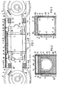
- Fig. 1 einen Hohlwellenantrieb im Längsschnitt,
- Fig. 2 und 3 Querschnitte des Gegenstandes der Fig. 1.
- Ein Gleisfahrzeug ist mit seinem nicht dargestellten Aufbau über ebenfalls nicht dargestellte übliche Drehkränze auf Fahrgestellen gelagert, von denen eines mit einem gezeigten Hohlwellenantrieb versehen ist. Jeder Hohlwellenantrieb enthält einen gehäuselosen Fahrmotor 1, dessen Ständerblechpaket 1A von achteckiger Kontur an beiden Stirnseiten mit Druckringen 2 versehen ist, die in nicht dargestellter bekannter Weise durch am Umfang angeordnete Klammern gegen das Ständerblechpaket 1A angepreßt sind und dieses zusammenhalten. Mit den Druckringen 2 sind Getriebegehäuse 3 lösbar verbunden, in denen die Motorwelle sowie die Getriebewellen gelagert sind, so daß gesonderte Lagerschilde in Fortfall kommen. Jedes Getriebegehäuse 3 weist einen an den zugeordneten Druckring 2 angrenzenden Lüfterkammerabschnitt 3A, einen schlankeren Getriebegehäusehals 3B sowie einen endseitigen Getriebegehäusekopf 3C auf, der sich an einer mit dem Getriebe gekuppelten Hohlwelle 4 abstützt, die jeweils eine Treibachse 5 für Antriebsräder 6 umgibt und mit diesen in nicht näher dargestellter bekannter Weise mechanisch gekuppelt ist. Jedes Getriebegehäuse 3 hat im Bereich des Lüfterkammerabschnittes 3A Luftdurchlässe 3D für die das Motorinnere durchströmende Kühlluft. Im Bereich mindestens eines Lüfterkammerabschnittes 3A ist auf der Motorwelle ein nicht dargestellter Lüfter befestigt, der die Kühlluft durch das Motorinnere fördert. Im Bereich der Getriebegehäusehälse 3B ragen seitlich Gehäuseteile 8, 9 für von außen beeinflußbare Hilfseinrichtungen (Bremsdruckzylinder, Kabel usw.) vor, die von außen zugänglich sein müssen und das Motor- und Getriebeinnere nach außen abdichten.
- Der Bereich von Getriebegehäusehals 3B zu Getriebegehäusehals 3B ist von einer axial geteilten Schallminderungskapsel 10 umhüllt, die aus entdröhnten Deck-, Seiten- und Bodenflächen 10A, 10B, 10C besteht, und die Schalldämpfungsmittel 11, 12, 13 in besonderer Anordnung und Gestaltung aufweist, wie dies nachfolgend näher dargelegt ist.
- Die Schallminderungskapsel besteht aus entdröhnten Blechen, d.h. mit körperschalldämpfendem Antidröhnmaterial beschichteten Blechen aus Eisen, Aluminium oder anderem Metall, bei denen die relativ dünnwandigen Bleche mit einer weniger als dreifach dickeren Antidröhnschicht versehen sind, damit die von im Inneren der Schallminderungskapsel liegenden Schallimmisionsquellen ausgehenden Schallwellen auf einen anderen als den Immisionsort reflektiert werden. Da bei der Schalldämmung keine Energieumwandlung stattfindet, tritt im freien Innenraum.der Schallminderungskapsel 10 ein Schallstau auf, dessen Schallinterferenzen bzw. stehende Schallwellen eine Erhöhung des Schallpegels bewirken würde, wenn keine Schalldämpfungsmittel 11, 12, 13 an besonderen Innenstellen der Schallminderungskapsel vorgesehen wären.
- Um dem Schallfeld die gestaute Schallenergie weitgehend zu entziehen, werden die Seitenflächen 10B und die Deckfläche 10A mit an die Wellenlänge der am meisten störenden magnetischen Töne angepaßten Schalldämpfungsmitteln 11, 12 so belegt, daß trotz der zwecks Einhaltung eines ausreichenden Abstandes zur Gleisoberkante OS bei'Freilassung eines Luftkanals 14 zwischen beiden Getriebegehäusen 3 und der nur entdröhnten Bodenfläche 10C eine starke Geräuschminderung eintritt.
- Die Schallminderungskapsel 10 hat in axialer Richtung bei der Teilfuge 15 geteilte Seitenflächen 10B, deren untere Abschnitte eine Einheit mit der Bodenfläche 10C und deren obere Abschnitte eine Einheit mit der Deckfläche 10A bilden, derart, daß der untere Teil der Schallminderungskapsel 10 abnehmbar ist. Ausnehmungen in den Abschnitten der beiden Seitenflächen 10B umschließen die schon genannten vorragenden Gehäuseteile 8, 9. Der obere Teil der Geräuschminderungskapsel 10 ist körperschallisoliert bei 18, 19 an den Druckringen 2 und den Getriebegehäusen 3 im Bereich der Luftdurchlässe 3D abgestützt.
- Um die Lüftergeräusche herabzusetzen, sind an den offenen Stirnseiten der Luftminderungskapsel 10 die Getriebegehäusehälse 3B mit Abstand 20 umgebend jeweils eine geteilte Schalldämpfungswand 13 vorgesehen, die mit der Bodenfläche 10C und den Seitenflächen 10B dicht verbunden sind, jedoch einen Freiraum 16 zur Deckfläche 10A aufweisen. Das Ständerblechpaket 1A ist von den Schalldämpfungsmitteln 11, 12 der Deck- und Seitenflächen 10A, 10B bis auf vier eckseitige Freiräume 17 dicht umgeben, die zwei axiale Luftkanäle im Bereich der achteckigen Ständerblechkontur und einen weiteren Kanal 14 zwischen Bodenfläche 10C und Ständerblechpaket 1A bilden, um einen Wärmestau im Fahrmotor 1 zu vermeiden. Die Wandstärke der einzelnen Schalldämpfungsmittel 11, 12, 13 ist sowohl für die ausreichende Schalldämpfung als auch für eine ausreichende Kühlluftförderung durch und um den Fahrmotor bemessen. Die Schallminderungskapsel 10 kann dabei die Sicherungsfunktion der unerwünschterweise Geräusche bildenden Luftdeckel übernehmen, wobei die Luftdurchlässe 3D in den Getriebegehäusen 3B durch geräuschfreie Kunststoffgitter 7 noch zusätzlich gesichert sein können.
- Um von den Getriebegehäuseköpfen 3C ausgestrahlte Geräusche zu mindern, können diesen in nicht gezeigter Weise zusätzliche stirnseitige Geräuschdämpfungsschürzen körperschallisoliert vorgelagert sein.
- Die Schalldämpfungsmittel können vorzugsweise aus Stein-und Glasfasermaterial, insbesondere in Form fester, plattenförmiger Beläge bestehen.
Claims (5)
Priority Applications (3)
| Application Number | Priority Date | Filing Date | Title |
|---|---|---|---|
| DE8383112095T DE3375996D1 (en) | 1983-12-01 | 1983-12-01 | Hollow drive shaft for rail vehicles |
| AT83112095T ATE33004T1 (de) | 1983-12-01 | 1983-12-01 | Hohlwellenantrieb fuer ein schienenfahrzeug. |
| EP83112095A EP0144451B1 (de) | 1983-12-01 | 1983-12-01 | Hohlwellenantrieb für ein Schienenfahrzeug |
Applications Claiming Priority (1)
| Application Number | Priority Date | Filing Date | Title |
|---|---|---|---|
| EP83112095A EP0144451B1 (de) | 1983-12-01 | 1983-12-01 | Hohlwellenantrieb für ein Schienenfahrzeug |
Publications (3)
| Publication Number | Publication Date |
|---|---|
| EP0144451A2 true EP0144451A2 (de) | 1985-06-19 |
| EP0144451A3 EP0144451A3 (en) | 1985-11-06 |
| EP0144451B1 EP0144451B1 (de) | 1988-03-16 |
Family
ID=8190848
Family Applications (1)
| Application Number | Title | Priority Date | Filing Date |
|---|---|---|---|
| EP83112095A Expired EP0144451B1 (de) | 1983-12-01 | 1983-12-01 | Hohlwellenantrieb für ein Schienenfahrzeug |
Country Status (3)
| Country | Link |
|---|---|
| EP (1) | EP0144451B1 (de) |
| AT (1) | ATE33004T1 (de) |
| DE (1) | DE3375996D1 (de) |
Family Cites Families (6)
| Publication number | Priority date | Publication date | Assignee | Title |
|---|---|---|---|---|
| DE2514265C3 (de) * | 1975-03-27 | 1979-06-13 | Siemens Ag, 1000 Berlin Und 8000 Muenchen | Antrieb für ein elektrisches Schienenfahrzeug |
| GB1528044A (en) * | 1975-07-18 | 1978-10-11 | British Leyland Uk Ltd | Motor vehicles |
| DE2933706B2 (de) * | 1979-08-21 | 1981-07-02 | Thyssen Industrie Ag, 4300 Essen | Drehgestell für Schienenfahrzeuge, z.B. Straßenbahnen |
| DE2952188A1 (de) * | 1979-12-22 | 1981-06-25 | Magirus-Deutz Ag, 7900 Ulm | Nutzfahrzeug mit einer im wesentlichen innerhalb der umrisse des fahrerhauses angeordneten kapsel zur aufnahme eines antriebsaggregates |
| DE3030594A1 (de) * | 1980-08-11 | 1982-02-18 | Siemens AG, 1000 Berlin und 8000 München | Triebaggregat fuer die treibachsen von schienenfahrzeugen |
| DE3202811A1 (de) * | 1982-01-26 | 1983-08-04 | Siemens AG, 1000 Berlin und 8000 München | Triebaggregat fuer die treibachsen von schienenfahrzeugen |
-
1983
- 1983-12-01 AT AT83112095T patent/ATE33004T1/de not_active IP Right Cessation
- 1983-12-01 DE DE8383112095T patent/DE3375996D1/de not_active Expired
- 1983-12-01 EP EP83112095A patent/EP0144451B1/de not_active Expired
Also Published As
| Publication number | Publication date |
|---|---|
| DE3375996D1 (en) | 1988-04-21 |
| EP0144451B1 (de) | 1988-03-16 |
| EP0144451A3 (en) | 1985-11-06 |
| ATE33004T1 (de) | 1988-04-15 |
Similar Documents
| Publication | Publication Date | Title |
|---|---|---|
| EP0138807B1 (de) | Antriebsvorrichtung | |
| DE102011012429A1 (de) | Rotorwelle und Elektromotor | |
| EP3116106B1 (de) | Elektrische maschine mit schalldämmung | |
| DE29518401U1 (de) | Fahrwerk für Nutzfahrzeuge | |
| EP0749643B1 (de) | Elektromotor | |
| DE9416306U1 (de) | Antriebseinheit für ein Hebezeug | |
| EP0046135B1 (de) | Triebaggregat für die Treibachsen von Schienenfahrzeugen | |
| DE2850816A1 (de) | Brennkraftmaschine | |
| EP1377488B1 (de) | Schienentriebfahrzeug mit einer antriebsvorrichtung und geräuschdämmenden mitteln | |
| DE2403254A1 (de) | Vorrichtung zur daempfung des motorgeraeuschs in kraftfahrzeugen | |
| DE1108721B (de) | Fuer Schienentriebfahrzeuge mit einer Brennkraftmaschine bestimmte Kuehlanlage | |
| EP0144451B1 (de) | Hohlwellenantrieb für ein Schienenfahrzeug | |
| DE69400943T2 (de) | In Harz gegossenen elektrischen Motor mit Vibrationsisolator aus Gummi | |
| DE69723779T2 (de) | Eisenbahnräder mit Schalldämpfungsvorrichtung | |
| DE2844269A1 (de) | Brennkraftmaschine mit schalldaemmender verschalung | |
| EP0074941B1 (de) | Schallisolierende Anordnung einer Verbrennungskraftmaschine | |
| DE2850579C3 (de) | Kühlanlage für eine flüssigkeitsgekühlte Brennkraftmaschine in einem Kraftfahrzeug | |
| AT398607B (de) | Gekapselte brennkraftmaschine zum antrieb von kraftfahrzeugen | |
| DE4233759A1 (de) | Hebezeugantrieb | |
| DE19531956A1 (de) | Einzelradantrieb für ein elektrisch angetriebenes Fahrzeug | |
| DE4109814C2 (de) | ||
| EP1533521A1 (de) | Windkraftanlage mit verminderter Schallabstrahlung | |
| EP0435847B1 (de) | Brennkraftmaschine mit hin- und hergehenden Kolben | |
| DE10136030B4 (de) | Trommelantrieb für eine Fahrtreppe oder einen Fahrsteig | |
| EP1029822A1 (de) | Schräganordnung eines Seilaufzugsantriebes |
Legal Events
| Date | Code | Title | Description |
|---|---|---|---|
| PUAI | Public reference made under article 153(3) epc to a published international application that has entered the european phase |
Free format text: ORIGINAL CODE: 0009012 |
|
| AK | Designated contracting states |
Designated state(s): AT CH DE FR GB IT LI NL SE |
|
| PUAL | Search report despatched |
Free format text: ORIGINAL CODE: 0009013 |
|
| AK | Designated contracting states |
Designated state(s): AT CH DE FR GB IT LI NL SE |
|
| 17P | Request for examination filed |
Effective date: 19860430 |
|
| 17Q | First examination report despatched |
Effective date: 19870326 |
|
| GRAA | (expected) grant |
Free format text: ORIGINAL CODE: 0009210 |
|
| AK | Designated contracting states |
Kind code of ref document: B1 Designated state(s): AT CH DE FR GB IT LI NL SE |
|
| PG25 | Lapsed in a contracting state [announced via postgrant information from national office to epo] |
Ref country code: NL Effective date: 19880316 Ref country code: IT Free format text: LAPSE BECAUSE OF FAILURE TO SUBMIT A TRANSLATION OF THE DESCRIPTION OR TO PAY THE FEE WITHIN THE PRESCRIBED TIME-LIMIT;WARNING: LAPSES OF ITALIAN PATENTS WITH EFFECTIVE DATE BEFORE 2007 MAY HAVE OCCURRED AT ANY TIME BEFORE 2007. THE CORRECT EFFECTIVE DATE MAY BE DIFFERENT FROM THE ONE RECORDED. Effective date: 19880316 Ref country code: FR Free format text: THE PATENT HAS BEEN ANNULLED BY A DECISION OF A NATIONAL AUTHORITY Effective date: 19880316 |
|
| REF | Corresponds to: |
Ref document number: 33004 Country of ref document: AT Date of ref document: 19880415 Kind code of ref document: T |
|
| REF | Corresponds to: |
Ref document number: 3375996 Country of ref document: DE Date of ref document: 19880421 |
|
| EN | Fr: translation not filed | ||
| NLV1 | Nl: lapsed or annulled due to failure to fulfill the requirements of art. 29p and 29m of the patents act | ||
| GBV | Gb: ep patent (uk) treated as always having been void in accordance with gb section 77(7)/1977 [no translation filed] | ||
| PG25 | Lapsed in a contracting state [announced via postgrant information from national office to epo] |
Ref country code: GB Free format text: LAPSE BECAUSE OF NON-PAYMENT OF DUE FEES Effective date: 19881123 |
|
| PG25 | Lapsed in a contracting state [announced via postgrant information from national office to epo] |
Ref country code: AT Effective date: 19881201 |
|
| PG25 | Lapsed in a contracting state [announced via postgrant information from national office to epo] |
Ref country code: LI Effective date: 19881231 Ref country code: CH Effective date: 19881231 |
|
| PLBE | No opposition filed within time limit |
Free format text: ORIGINAL CODE: 0009261 |
|
| STAA | Information on the status of an ep patent application or granted ep patent |
Free format text: STATUS: NO OPPOSITION FILED WITHIN TIME LIMIT |
|
| 26N | No opposition filed | ||
| REG | Reference to a national code |
Ref country code: CH Ref legal event code: PL |
|
| PG25 | Lapsed in a contracting state [announced via postgrant information from national office to epo] |
Ref country code: DE Effective date: 19890901 |
|
| PG25 | Lapsed in a contracting state [announced via postgrant information from national office to epo] |
Ref country code: SE Effective date: 19891202 |
|
| EUG | Se: european patent has lapsed |
Ref document number: 83112095.1 Effective date: 19900104 |